1
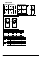
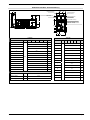
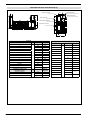
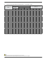
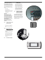
Installation Manual
• WATER COOLED CHILLER AND HEAT
PUMP
NXW
• INDOOR UNITS
• SCROLL COMPRESSORS
EN
INXWPY. 14.03. 4437830_02
Dear Customer,
Thank you for choosing an AERMEC product. This product is the result of many years of experience and
in-depth engineering research, and it is built using top quality materials and advanced technologies.
In addition, the CE mark guarantees that our appliances fully comply with the requirements of the European
Machinery Directive in terms of safety. We constantly monitor the quality level, and as a result AERMEC
products are synonymous with Safety, Quality, and Reliability.
The data may be subject to modifications deemed necessary for improving the product at any time and
without forewarning.
Thank you again.
AERMEC S.p.A
AERMEC S.p.A. reserves the right to make any modifications considered necessary to improve its products at any moment and is not obliged to add these modifications to
machines that have already been manufactured, delivered or are under construction.
summary
2.1.
Minimum Technical Spaces (Mm/In)....................................... 5
1.
Selection And Place Of Installation ......................................... 5
2.
Positioning............................................................................... 5
3.
Dimensional Tables.................................................................. 6
4.
Hydraulic Circuit...................................................................... 9
4.1.
External Hydraulic Circuit Recommended............................... 9
4.2.
System Load ............................................................................ 9
4.3.
Emptying The System.............................................................. 9
5.
Percentage Distribution Of Weights On Supports ............... 10
4.4.
Percentage Distribution Of Weights On Supports .................... (Version ° - Size From 0700 To 1400) .................................... 10
5.1.
Percentage Distribution Of Weights On Supports .................... (Version ° - Size From 0500 L To 0800 L) ............................... 11
5.2.
Percentage Distribution Of Weights On Supports .................... (Version ° - Size From 0900 L To 1400 L) ............................... 12
5.3.
Percentage Distribution Of Weights On Supports .................... (Version H - Size From 0900 To 1400) ................................... 13
5.4.
Percentage Distribution Of Weights On Supports .................... (Version H - Size From 0500 L To 0800 L) .............................. 14
5.5.
Percentage Distribution Of Weights On Supports .................... (Version H - Size From 0900 L To 1400 L) .............................. 15
6.
Electrical Wirings................................................................... 16
6.1.
Recommended Section Of Electric Cables............................. 16
6.2.
Connection To The Power Supply.......................................... 17
6.3.
Electrical Power Connection.................................................. 17
6.4.
Auxiliary Connections At The User/Installer Expense............ 17
7.
Control And First Start-Up..................................................... 18
7.1.
Preparation For Commissioning............................................ 18
7.2.
First Commissioning Of The Machine.................................... 18
7.3.
Season Changeover............................................................... 18
8.
Operation Characteristics...................................................... 19
8.1.
Cooling Set Point................................................................... 19
8.2.
Heating Set Point................................................................... 19
8.3.
Compressor Start-Up Delay................................................... 19
8.4.
Circulation Pump................................................................... 19
8.5.
Anti-Freeze Alarm.................................................................. 19
8.6.
Water Flow Rate Alarm.......................................................... 19
9.
Regular Maintenance............................................................ 19
10.
Extraordinary Maintenance................................................... 19
1.
SELECTION AND PLACE OF
INSTALLATION
Before installing the unit, decide with the customer the position in which it will be placed,
pay attention to the following points:
− the support surface must be able to withstand the weight of the unit;
−
−
2.
The NXW series are for indoor use (protection grade IP40) and must be installed
leaving the necessary technical spaces (see
"Minimum technical spaces"). Observance of these spaces is to be considered
indispensable in order to allow normal and
extraordinary maintenance operations.
The unit must be installed by a qualified
technician in accordance with the national
laws in force in the country of installation.
POSITIONING
The machine is delivered from the factory
wrapped in estincoil.
Before moving the unit, check the lifting capacity of the machines used.
Once the packaging has been removed, the unit
must be handled by qualified personnel with the
suitable equipment. To transport the machine
use either a forklift or lifting belts (see figure)
−
The holes in the base to be used for lifting are indicated with yellow adhesives
showing a black arrow. The blades (not
included) which are adequately scaled
must protrude from the base unit for a
sufficient length so that the lifting straps
can be tautened upwards without them
encountering any interference.
− Make sure that the straps have been approved to support the weight of the unit,
be careful that they a properly fixed to the
upper frame and to the lifting blades, the
safety closure must ensure that the straps
do not work loose of their housing. The
hooking point of the lifting frame must be
on the vertical of the centre of gravity (see
transport figure). − In order to avoid damaging the unit with
the cables, insert protection elements
between them and the machine. It is absolutely forbidden to stand beneath the unit.
− Take into account that when the chiller is
working, vibrations may be generated; it is
therefore advisable to install anti-vibration
supports (AVX accessories), fitting them
to the holes in the base according to the
assembly diagram.
Note: for more information on the installation
position of the supports AVX, please contact
us
− Fasten the unit by checking carefully that
its on the same level; check that easy
access to the hydraulic and electric part is
allowed.
2.1. MINIMUM TECHNICAL SPACES (mm/in)
1000mm/39,4in
1000mm
39,4in
1000mm
39,4in
1000mm/39,4in
1000mm/39,4in
fig.1
ATTENTION
Use all of the available holes for lifting
The blades not included
INXWPY. 1403. 4437830_02 5
3.
DIMENSIONAL TABLES
750-800-900-1000-1250-1400 [L]
NXW 0500-0550-0600-0650-0700 [L]
A
A
C
C
B
with pump
without pump
CN
OUT
EV
IN
EV
IN
CN
OUT
CN
IN
EV
OUT
EV
OUT
CN
IN
EV
OUT
CN
OUT
EV
IN
CN
IN
EV
IN
EV
OUT
CN
IN
B
B
version [°]
Model
version [H]
version [°]
U.M. 0500 0550 0600 0650 0700 0750 0800 0900 1000 1250 1400
EVAPORATOR (PLATES)
Hydraulic connection
Victaulic in/out
Ø
2"
1/2
2"
1/2
2"
1/2
2"
1/2
2"
1/2
2"
1/2
2"
1/2
2"
1/2
3"
3"
3"
Ø
2"
1/2
2"
1/2
2"
1/2
2"
1/2
2"
1/2
2"
1/2
2"
1/2
2"
1/2
3"
3"
3"
CONDENSER (PLATES)
Hydraulic connection
Victaulic in/out
NXW
DIMENSIONS (without pumps) 0500 0550 0600 0650 0700 0750 0800 0900 1000 1250 1400
mm
1885
1885
Hight A
in
74,2
74,2
mm
800
800
L
Width C
in
31,5
31,5
mm
2090
2420
Lenght B
in
82.28
95,28
Hight A
Width C
Lenght B
6
HL
CN
OUT
mm
in
mm
in
mm
in
INXWPY. 1403. 4437830_02
1885
74,2
800
31,5
2090
82.28
1885
74,2
800
31,5
2420
95,28
version [H]
A
B
B
A
NXW 0500~0750 WITH TOTAL RECOVERY (T)
E
E
Outlet condenser
Outlet condenser
Uscita
condensatore
B
F
Inlet condenser
Ingresso condesatore
O
A
B
F
Inlet
evaporator
Ingresso
evaporatore
O
G
Outlet
Uscitaevaporator
evaporatore
Outlet total recovery
Uscita recupero totale
D
A
P
Inlet total recupero
recovery totale
Ingresso
H
C
N
P
I
L
M
N
POSITION
POSITION
Model
U.M.
0500
0550
0600
0650
0700
0750
Model
U.M. 0500 0550 0600 0650 0700 0750
A
69,9
69,9
B
11,8
11,8
A
1775
1775
B
300
300
C
2644
3044
D
1553
1818
C
104,1
119,8
E
343
343
D
61,1
71,6
F
225
225
E
13,5
13,5
G
369
568
F
8,9
8,9
1125
1165
I
369
568
G
14,5
22,4
L
220
260
44,3
45,9
M
233
213
I
14,5
22,4
N
800
800
L
8,7
10,2
O (NXP°/H)
369
369/568
M
9,2
8,4
P
1125
1125
N
31,5
31,5
O (NXP °)
14,5
14,5
H
mm
HYDRAULIC CONNECTION (VICTAULIC IN/OUT)
Evaporator (plates)
Ø
2”1/2
Condenser (plates)
Ø
2”1/2
Total recovery(plates)
Ø
2”1/2
H
in
O (NXP L)
P
22,4
44,3
44,3
INXWPY. 1403. 4437830_02 7
A
A
E
F
B
C
A
NXW
0800~1400 WITH TOTAL RECOVERY (T)
E
Outlet condenser
B
Inlet evaporator
F
B
Outlet evaporator
Inlet condeser
O
D
A
P
O
Outlet total recovery
A
Inlet total recovery
P
H I
C
N
G
L
M
POSITION
Model
U.M.
A
B
C
D
E
F
G
H
mm
I
L
M
N
O (NXW°)
O (NXW H)
P
HYDRAULIC CONNECTION
U.M.
(VICTAULIC IN/OUT)
Evaporator (plates)
Ø
Condensater (plates)
Total Recovery (plates)
8
INXWPY. 1403. 4437830_02
0800-0900
1775
300
3044
1818
343
225
568
1165
568
260
213
800
369
568
1125
0800-0900
2”1/2
2”1/2
2”1/2
1000-1400
1775
300
3044
1818
343
225
568
1165
568
260
213
800
568
1125
0900 H
1000-1400
3”
3”
3”
N
POSITION
Model
0800-0900
1000-1400
A
69,9
69,9
B
11,8
11,8
C
119,8
119,8
D
71,6
71,6
E
13,5
13,5
F
8,9
8,9
G
22,4
22,4
H
U.M.
in
45,9
45,9
I
22,4
22,4
L
10,2
10,2
M
8,4
8,4
31,5
N
31,5
O (NXW°)
14,5
O (NXW H)
22,4
P
44,3
22,4
44,3
B
4.
HYDRAULIC CIRCUIT
The NXW standard version is comprised of a
circuit including:
− Evaporator (plate type exchanger)
− Condenser (plate type exchanger)
− Water inlet probe SIW
− Water outlet probe SUW
NB:
Water filter versions standard: NOT INCLUDED
the weld pipe is supplied as
standard with the VICTAULIC connection is
included
The NXW version with pumping group also
includes:
−Circulation pump
−Water filter
−Drain valve
−Flow switch
−Water outlet/inlet probe
−Expansion tank (25 litres)
4.1.
EXTERNAL HYDRAULIC CIRCUIT RECOMMENDED
The selection and installation of components
outside the NXW should be carried out by the installer, who should work according to the technical
code of practice and in compliance with the legislation in force in the country of destination (MD
329/2004).
Before connecting the pipes make sure that
they do not contain stones, sand, rust, slag or
any foreign bodies that may damage the system.
It is necessary to make a by-pass to the unit to
be able to carry out the cleaning of the pipes
without having to disconnect the machine. The
connection pipes must be properly supported
so as not to burden the unit with their weight.
On the water circuit, it is advisable to install
the following instruments, if not foreseen in
the version you have:
1. Two pressure gauges of suitable size
(input and output section).
2. Two anti-vibration couplings (input and
output section).
3. Two shut-off valves (normal input section,
output section calibrating valve).
4. Two thermometers (input and output section).
5. Expansion tanks
6.Pump
7. Accumulation tank
8. Flow switch
9. Safety valve
10. Charging unit
11. Water filter
11. The filter protects only the exchangers
(in case of particularly dirty water, we
recommend an external filter to protect
the pumps)
Compulsory hydraulic circuit compnents (in
case of an NXW provided without the hydronic
kit (evaporator side, condenser side):
- At the inlet or each plate heat exchanger the
installation of a flow switch (not included) is
compulsory at the penalty of invalidating the
warranty.
- Installation of the mechanical filter is compulsory
at the inlet of each plate heat exchanger at the
penalty of invalidating the warranty. The filter
must have filtering holes with a diameter not
greater than one millimetre and must be kept
clean, therefore the cleaning must be verified
after installation of the unit and the condition
must be checked periodically.
It is necessary, that the water flow rate to the
chiller unit complies with the values reported in
the performance tables.
−
−
−
−
Open all the drain valves of the system and
of the related terminals.
Open the shut-off devices of the system.
Start the filling by slowly opening the
water system load cock placed outside the
machine.
When water begins to flow from the terminal vent valves, close them and continue
loading up to read on the gauge the value
of 1.5 bar.
The system is loaded at a pressure between 1
and 2 bar.
It is advisable to repeat this operation once the
machine has worked for some hours and to
periodically check the system pressure, restoring if it drops below 1 bar.
Check the hydraulic seal of the joints.
4.3.
EMPTYING THE SYSTEM
−
Before starting to drain the system, turn
"off" the unit
− Check that the water system load/restore
tap is closed
− Open the drain tap outside the machine
and all the vent valves of the system and
the corresponding terminals.
If the system uses glycol, this liquid should not
be drained to the environment because it is a
pollutant. It must be collected and, if possible,
reused.
The systems loaded with anti-freeze or specific
regulations, need the water backflow system.
Special supply/recovery water, is carried out with
appropriate treatment systems.
4.2.
−
SYSTEM LOAD
Before starting the load, check that the
system drain tap is closed.
WATER FEATURES
Example of NXW Version [H]
PH
Electric conductivity
1
5
7
3
8
4
2
HYDRAULIC CIRCUIT KEY
(PUMP VERSION)
1 Condenser
2 Evaporator
3 Flow switch
4Pumps
5 Air bleed valve
6 Water discharge
7 Filter
8 Expansion tank
Chloride ions
Sulphuric acid ions
Total iron
Alkalinity M
Total hardness
Sulphur ions
ammonia ions
Silicone ions
6-8
less than 200 mV/cm
(25°C)
less than 50 ppm
less than 50 ppm
less than 0.3 ppm
less than 50 ppm
less than 50 ppm
none
none
less than 30 ppm
NB
The Victaulic joints and the soldering studs for
the condenser and evaporator are provided
INXWPY. 1403. 4437830_02 9
5.
PERCENTAGE DISTRIBUTION OF WEIGHTS ON SUPPORTS
4.4.
PERCENTAGE DISTRIBUTION OF WEIGHTS ON SUPPORTS (MODEL ° - SIZE FROM 0500 L TO 0800 L)
EMPTY
MODEL
kg
PERCENTAGE WEIGHT DISTRIBUTION ON
SUPPORTS (%)
CENTRE OF GRAVITY
Weight
mm
lb
Xg
in
Yg
Xg
Yg
B
C
D
NXW0500 L
°
730
1610
391
928
15
37
25%
24%
26%
25%
NXW0500 L
° + 1pumps
928
2047
385
1127
15
44
30%
28%
22%
20%
NXW0500 L
° + 2pumps
992
2187
384
1184
15
47
29%
27%
23%
21%
NXW0500 L
° + 3pumps
1056
2328
382
1233
15
49
28%
26%
24%
22%
NXW0500 L
° + 4pumps
1120
2469
381
1277
15
50
28%
25%
25%
23%
NXW0550 L
°
791
1744
397
887
16
35
26%
26%
24%
24%
NXW0550 L
° + 1pumps
989
2180
391
1083
15
43
31%
29%
21%
20%
NXW0550 L
° + 2pumps
1053
2321
389
1138
15
45
30%
28%
22%
21%
NXW0550 L
° + 3pumps
1117
2461
388
1187
15
47
29%
27%
23%
21%
NXW0550 L
° + 4pumps
1180
2602
386
1231
15
48
28%
26%
24%
22%
NXW0600 L
°
792
1746
398
888
16
35
26%
26%
24%
24%
NXW0600 L
° + 1pumps
990
2183
391
1083
15
43
31%
29%
21%
20%
NXW0600 L
° + 2pumps
1054
2323
389
1138
15
45
30%
28%
22%
21%
NXW0600 L
° + 3pumps
1118
2464
388
1188
15
47
29%
27%
23%
21%
NXW0600 L
° + 4pumps
1181
2605
386
1231
15
48
28%
26%
24%
22%
NXW0650 L
°
878
1935
405
927
16
37
25%
25%
25%
25%
NXW0650 L
° + 1pumps
1089
2401
397
1110
16
44
30%
29%
21%
20%
NXW0650 L
° + 2pumps
1166
2571
394
1169
16
46
29%
28%
22%
21%
NXW0650 L
° + 3pumps
1230
2711
393
1212
15
48
28%
27%
23%
22%
NXW0650 L
° + 4pumps
1294
2852
391
1251
15
49
27%
26%
24%
23%
NXW0700 L
°
887
1955
405
926
16
36
25%
25%
25%
25%
NXW0700 L
° + 1pumps
1098
2420
397
1108
16
44
30%
29%
21%
20%
NXW0700 L
° + 2pumps
1175
2590
395
1166
16
46
29%
28%
22%
21%
NXW0700 L
° + 3pumps
1252
2760
393
1218
15
48
28%
27%
23%
22%
NXW0700 L
° + 4pumps
1329
2930
391
1263
15
50
27%
26%
24%
23%
NXW0750 L
°
1030
2270
407
1184
16
47
22%
23%
27%
28%
NXW0750 L
° + 1pumps
1279
2820
398
1434
16
56
29%
29%
21%
21%
NXW0750 L
° + 2pumps
1395
3075
395
1504
16
59
28%
28%
22%
22%
NXW0750 L
° + 3pumps
1472
3245
394
1544
16
61
28%
27%
23%
22%
NXW0750 L
° + 4pumps
1549
3415
392
1580
15
62
27%
26%
24%
23%
NXW0800 L
°
1073
2364
403
1268
16
50
24%
24%
26%
26%
NXW0800 L
° + 1pumps
1297
2859
396
1444
16
57
30%
29%
21%
21%
NXW0800 L
° + 2pumps
1412
3114
394
1512
15
60
29%
28%
22%
21%
NXW0800 L
° + 3pumps
1489
3284
392
1551
15
61
28%
27%
23%
22%
NXW0800 L
° + 4pumps
1566
3453
391
1587
15
62
28%
27%
23%
22%
NOTE
- The number of pumps refers to the quantity physically present on the machine.
- The weight difference between the types of configurator pumps (low head and high head) is negligible.
10
A
INXWPY. 1403. 4437830_02
5.1.
PERCENTAGE DISTRIBUTION OF WEIGHTS ON SUPPORTS (MODEL ° - SIZE FROM 0900 L TO 1400 L)
EMPTY
MODEL
kg
PERCENTAGE WEIGHT DISTRIBUTION ON
SUPPORTS (%)
CENTRE OF GRAVITY
Weight
mm
lb
Xg
in
Yg
Xg
Yg
A
B
C
D
NXW0900 L
°
1265
2789
412
1195
16
47
25%
26%
24%
25%
NXW0900 L
° + 1pumps
1527
3366
404
1445
16
57
29%
30%
21%
21%
NXW0900 L
° + 2pumps
1642
3621
401
1524
16
60
28%
28%
22%
22%
NXW0900 L
° + 3pumps
1758
3875
398
1592
16
63
27%
27%
23%
23%
NXW0900 L
° + 4pumps
1873
4130
396
1653
16
65
27%
26%
24%
24%
NXW1000 L
°
1569
3458
418
1300
16
51
22%
24%
26%
28%
NXW1000 L
° + 1pumps
1867
4115
409
1514
16
60
28%
29%
21%
22%
NXW1000 L
° + 2pumps
2019
4450
406
1593
16
63
27%
28%
23%
23%
NXW1000 L
° + 3pumps
2134
4705
404
1646
16
65
26%
27%
23%
24%
NXW1000 L
° + 4pumps
2250
4959
402
1693
16
67
26%
26%
24%
24%
NXW1250 L
°
1676
3696
416
1317
16
52
22%
24%
26%
28%
NXW1250 L
° + 1pumps
1975
4353
408
1517
16
60
28%
29%
21%
22%
NXW1250 L
° + 2pumps
2126
4688
405
1592
16
63
27%
27%
23%
23%
NXW1250 L
° + 3pumps
2242
4942
403
1642
16
65
26%
27%
23%
24%
NXW1250 L
° + 4pumps
2357
5197
401
1688
16
66
26%
26%
24%
24%
NXW1400 L
°
1826
4026
416
1346
16
53
21%
23%
27%
29%
NXW1400 L
° + 1pumps
2124
4683
408
1527
16
60
27%
29%
21%
22%
NXW1400 L
° + 2pumps
2276
5018
405
1597
16
63
27%
27%
23%
23%
NXW1400 L
° + 3pumps
2391
5272
403
1644
16
65
26%
27%
23%
24%
NXW1400 L
° + 4pumps
2507
5527
401
1686
16
66
26%
26%
24%
24%
NOTE
- The number of pumps refers to the quantity physically present on the machine.
- The weight difference between the types of configurator pumps (low head and high head) is negligible.
INXWPY. 1403. 4437830_02 11
5.2.
PERCENTAGE DISTRIBUTION OF WEIGHTS ON SUPPORTS (MODEL H - SIZE FROM 0500 L TO 0800 L)
EMPTY
MODEL
kg
PERCENTAGE WEIGHT DISTRIBUTION ON
SUPPORTS (%)
CENTRE OF GRAVITY
Weight
mm
lb
Xg
in
Yg
Xg
Yg
B
C
D
NXW0500 L
H
782
1724
385
936
15
37
26%
24%
26%
24%
NXW0500 L
H + 1pumps
980
2161
380
1123
15
44
31%
28%
22%
20%
NXW0500 L
H + 2pumps
1044
2301
379
1177
15
46
30%
27%
23%
21%
NXW0500 L
H + 3pumps
1108
2442
379
1224
15
48
29%
26%
24%
21%
NXW0500 L
H + 4pumps
1172
2583
378
1267
15
50
28%
25%
25%
22%
NXW0550 L
H
843
1858
391
897
15
35
26%
25%
25%
24%
NXW0550 L
H + 1pumps
1041
2294
386
1081
15
43
31%
29%
21%
19%
NXW0550 L
H + 2pumps
1104
2435
385
1134
15
45
30%
28%
22%
20%
NXW0550 L
H + 3pumps
1168
2575
384
1181
15
47
29%
27%
23%
21%
NXW0550 L
H + 4pumps
1232
2716
383
1224
15
48
29%
26%
24%
22%
NXW0600 L
H
879
1938
390
920
15
36
26%
25%
25%
24%
NXW0600 L
H + 1pumps
1077
2374
385
1093
15
43
31%
29%
21%
20%
NXW0600 L
H + 2pumps
1141
2515
384
1144
15
45
30%
28%
22%
20%
NXW0600 L
H + 3pumps
1205
2655
383
1189
15
47
29%
27%
23%
21%
NXW0600 L
H + 4pumps
1268
2796
382
1230
15
48
28%
26%
24%
22%
NXW0650 L
H
941
2073
396
940
16
37
25%
24%
26%
25%
NXW0650 L
H + 1pumps
1152
2539
390
1111
15
44
30%
29%
21%
20%
NXW0650 L
H + 2pumps
1229
2709
388
1167
15
46
29%
28%
22%
21%
NXW0650 L
H + 3pumps
1293
2849
387
1208
15
48
29%
27%
23%
22%
NXW0650 L
H + 4pumps
1356
2990
386
1245
15
49
28%
26%
24%
22%
NXW0700 L
H
976
2151
396
953
16
38
24%
24%
26%
25%
NXW0700 L
H + 1pumps
1187
2617
390
1116
15
44
30%
29%
21%
20%
NXW0700 L
H + 2pumps
1264
2786
389
1170
15
46
29%
28%
22%
21%
NXW0700 L
H + 3pumps
1341
2956
387
1218
15
48
28%
27%
23%
22%
NXW0700 L
H + 4pumps
1418
3126
386
1260
15
50
28%
26%
24%
23%
NXW0750 L
H
1131
2493
392
1212
15
48
22%
21%
29%
28%
NXW0750 L
H + 1pumps
1381
3043
387
1439
15
57
24%
23%
28%
26%
NXW0750 L
H + 2pumps
1496
3298
385
1503
15
59
23%
21%
29%
27%
NXW0750 L
H + 3pumps
1573
3468
384
1541
15
61
22%
21%
30%
27%
NXW0750 L
H + 4pumps
1650
3638
383
1575
15
62
28%
26%
24%
22%
NXW0800 L
H
1164
2566
392
1289
15
51
24%
23%
27%
26%
NXW0800 L
H + 1pumps
1388
3060
387
1445
15
57
30%
28%
21%
20%
NXW0800 L
H + 2pumps
1504
3315
386
1508
15
59
29%
27%
22%
21%
NXW0800 L
H + 3pumps
1581
3485
385
1546
15
61
29%
27%
23%
21%
NXW0800 L
H + 4pumps
1658
3655
384
1579
15
62
28%
26%
24%
22%
NOTE
- The number of pumps refers to the quantity physically present on the machine.
- The weight difference between the types of configurator pumps (low head and high head) is negligible.
12
A
INXWPY. 1403. 4437830_02
5.3.
PERCENTAGE DISTRIBUTION OF WEIGHTS ON SUPPORTS (MODEL H - SIZE FROM 0900 L TO 1400 L)
EMPTY
MODEL
kg
PERCENTAGE WEIGHT DISTRIBUTION ON
SUPPORTS (%)
CENTRE OF GRAVITY
Weight
mm
lb
Xg
in
Yg
Xg
Yg
A
B
C
D
NXW0900 L
H
1524
3359
398
1290
16
51
23%
23%
27%
26%
NXW0900 L
H + 1pumps
1785
3936
393
1489
15
59
29%
28%
22%
21%
NXW0900 L
H + 2pumps
1901
4191
391
1555
15
61
28%
27%
23%
22%
NXW0900 L
H + 3pumps
2016
4445
389
1613
15
63
28%
26%
24%
23%
NXW0900 L
H + 4pumps
2132
4700
388
1664
15
66
27%
25%
25%
23%
NXW1000 L
H
1742
3841
404
1337
16
53
22%
23%
27%
28%
NXW1000 L
H + 1pumps
2041
4499
398
1528
16
60
28%
28%
22%
22%
NXW1000 L
H + 2pumps
2192
4833
396
1600
16
63
27%
27%
23%
23%
NXW1000 L
H + 3pumps
2308
5088
394
1648
16
65
27%
26%
24%
23%
NXW1000 L
H + 4pumps
2423
5342
393
1692
15
67
26%
25%
25%
24%
NXW1250 L
H
1792
3950
406
1333
16
52
22%
23%
27%
28%
NXW1250 L
H + 1pumps
2090
4608
400
1519
16
60
28%
28%
22%
22%
NXW1250 L
H + 2pumps
2242
4942
397
1590
16
63
27%
27%
23%
23%
NXW1250 L
H + 3pumps
2357
5197
396
1638
16
64
27%
26%
24%
23%
NXW1250 L
H + 4pumps
2473
5452
394
1682
16
66
26%
25%
25%
24%
NXW1400 L
H
1958
4317
404
1361
16
54
22%
22%
28%
28%
NXW1400 L
H + 1pumps
2256
4974
399
1530
16
60
28%
28%
22%
22%
NXW1400 L
H + 2pumps
2408
5309
397
1596
16
63
27%
27%
23%
23%
NXW1400 L
H + 3pumps
2523
5563
395
1640
16
65
27%
26%
24%
23%
NXW1400 L
H + 4pumps
2639
5818
394
1681
16
66
26%
25%
25%
24%
NOTE
- The number of pumps refers to the quantity physically present on the machine.
- The weight difference between the types of configurator pumps (low head and high head) is negligible.
INXWPY. 1403. 4437830_02 13
6.
ELECTRICAL WIRINGS
All electrical operations must be carried out BY QUALIFIED PERSONNEL, IN ACCORDANCE WITH THE CORRESPONDING REGULATIONS, trained and informed about the
risks related to such operations.
NXW chillers are completely wired in the factory
and only need the connection to the electricity
mains supply, downstream from a group switch,
according
to the regulations in force in the country
where the machine is installed.
It is also suggested to check:
−
−
−
−
−
−
−
−
14
The characteristics of electric lines and related components must be established by PERSONNEL AUTHORISED TO DESIGN ELECTRIC INSTALLATIONS, following international
regulations and the national regulations of the country in which the unit is installed, in
compliance with the legislative regulations in force at the moment of installation.
the mains supply characteristics, to ensure it is suitable for the levels indicated
in the electrical data table, also taking
into consideration any other equipment
that may be operating at the same time.
The unit is only powered after the last
(hydraulic and electric) installations.
Follow the connections instructions of the
phase conductors, and earth.
The power supply line will have a special
protection upstream against short circuits
and earth losses that sections the system
according to other users.
The voltage should be within a tolerance
of ± 10% of the rated supply voltage of the
machine (for Three-phase units displacement max 3% between the phases). If these
parameters are not respected, contact the
energy supplier. For electrical wirings use
isolated double cables according to the
standards in force in the different countries.
It is necessary to use a omnipolar thermomagnetic switch, in compliance with
the CEI-EN standards (contact opening
of at least 3 mm), with adequate switch
capability and differential protection
based on the followed electrical data
table, installed as close as possible to the
machine.
It is necessary to carry out an efficient
earth connection. The manufacturer can
not be held responsible for any damage
caused by the failure and ineffective
earthing of the machine.
For units with Three-phase power check
INXWPY. 1403. 4437830_02
For installation requirements, the wiring layout supplied with the unit must be compulsory referred to. The wiring layout together with the manuals must be kept in good conditions and readily ACCESSIBLE FOR FUTURE OPERATIONS ON THE UNIT.
IT is compulsory to check the machine sealing before connecting the electrical wirings.
The machine should only be powered once the hydraulic and electric operations are completed.
the correct connection of the phases.
WARNING:
It is forbidden to use water pipes for the
earthing of the machine.
6.1.
RECOMMENDED SECTION OF
ELECTRIC CABLES
The cable sections indicated in the table are
advised for a maximum length of 50m/164FT.
For higher lengths or different
types of cable installation, it will
be the DESIGNERS responsibility
to carefully measure the line main
switch, the supply power line and
the earthing protection connection, and the working connection
cables:
−
−
−
the length
the type of cable
Absorption of the unit and its
physical position, and room
temperature.
WARNING:
Check that all power cables
are correctly secured to the
terminals when switched on for
the first time and after 30 days
of use. Afterwards, check the
connection of the power cables
every six months.
Slack terminals could cause
the cables and components to
overheat.
6.2.
−
CONNECTION
− For the functional connection of the unit, run the
power supply cable to the
electrical panel inside the
unit fig. 1 and connect it to
the disconnecting switch
terminals observing the
phase and the earth. fig. 2
6.4.
AUXILIARY CONNECTIONS AT THE USER/
INSTALLER EXPENSE
For installation requirements, refer
to the wiring diagram supplied
with the unit. The wiring diagram
together with the manuals must be
kept in good conditions and readily
ACCESSIBLE FOR FUTURE OPERATIONS ON THE UNIT.
Fig.2
CONNECTION TO THE
POWER SUPPLY
Key fig. 2
Check there is no voltage on
the electric line you want to
use.
L1
Line 1
L2
Line 2
L3
Line 3
PE
Earth
6.2.1. To access the electric
box:
−
−
Turn the electrical panel
screws ¼ in counter-clockwise
direction
Turn the handle of the doorblock disconnecting switch to
OFF (see figure). In this way,
the electrical panel can be
accessed
6.3.
ELECTRICAL POWER
Fig.1
INXWPY. 1403. 4437830_02 15
7.
CONTROL AND FIRST START-UP
7.1.
PREPARATION FOR COMMISSIONING
Bear in mind that a free start-up service is offered by the Aermec Technical Service for the unit of
this series, at the request of Aermec customers or legitimate owners and in ITALY only.
The start-up must be previously agreed on the basis of the system implementation times. Before the
intervention of the AERMEC After Sales Service, all the operations (electrical and hydraulic hook ups,
loading and breather from the system) must be completed.
Before starting the unit make sure that:
− All the safety conditions have been respected
− The unit has been properly fixed to the support base
− The minimum technical spaces have been observed;
− Water connections have been performed respecting the input and output
− The hydraulic system has been loaded and vented.
− The hydraulic circuit taps are open
− The electrical wirings have been properly carried out;
− The voltage is within a tolerance of 10% of the unit rated voltage
− The earthing has been carried out correctly
− Tightening of all electrical and hydraulic connections have been well carried out.
7.2.
FIRST COMMISSIONING OF THE MACHINE
Before activating the unit:
- Close the electric panel lid.
- Position the door-block disconnecting switch of the machine on ON,
turning the handle down. (fig.3)
- The display on (fig.4) indicates that the unit is ready for operation.
For more information see the USER'S MANUAL
7.3.
SEASON CHANGEOVER
For the season changeover, see the user's manual.
Fig.3
Display on on
Fig.4
16
INXWPY. 1403. 4437830_02
WARNING
The first start-up has to be
carried out with the standard
settings, only when the test
is finished the values of the
operation Set Point vary.
Before starting up, power the
unit for at least 12-24 hours
by positioning the protection
thermomagnetic switch and
the door-block disconnecting
switch on ON fig.1
Make sure that the control
panel is turned off until it allows the oil heater system the
compressor casing.
8.
8.1.
OPERATION
CHARACTERISTICS
COOLING SET POINT
(Default defined) = 7°C, ∆t = 5°C.
8.2.
HEATING SET POINT
(Default defined) = 45°C, ∆t = 5°C.
In case of restoring of the unit supplied power
after a momentary interruption, the pre-set
mode is maintained in memory.
8.3.
COMPRESSOR START-UP DELAY
To prevent the compressor start too close to
each other, two functions have been arranged.
- Minimum time from last turnoff 60 seconds.
- Minimum time from last start 300 seconds.
8.4.
CIRCULATION PUMP
The electronic board provides an output to
manage the circulation pump.
After the first 10 seconds of pump operation,
when the water flow rate is running, activate
the function of water flow rate alarm (flow
switch).
8.5.
ANTI-FREEZE ALARM
The anti-freeze alarm is active as if the machine
is turned-off or if the machine is in standby
mode. In order to prevent breakage of the
plate-type exchanger due to freezing water
contained, the compressor is locked (if the
machine is turned on under 4° C) and the
heater starts up (if standby below 5° C). If the
temperature detected by the probe in the
exchanger output and in the chiller input is
below +4 ° C.
REGULAR
MAINTENANCE
9.6.1. Hydraulic circuit
minimum technical spaces for maintenance
WARNING
Inspection, maintenance
and possible repair operations
must be carried out only by an
authorised technician according to
the law.
Unsuitable check/maintenance operation may cause damage to things
and people.
The PGD1 provides the management of a water
flow rate alarm commanded from a flow switch
installed on the machine as standard. This
safety type can occur after the first 10 seconds
of operation of the pump if the water flow rate
is not sufficient.
This alarm sets the block of the compressor
and the pump.
The intervention of this alarm sets the
compressor block and not of the pump block,
which remains active, and the heater starts up
if installed.
For resetting the normal functions, the water
output temperature has to be over +4 °C, the
reset is manual.
WARNING:
AT ANY INTERVENTIONS OF THIS ALARM IT
IS RECOMMENDED TO IMMEDIATELY CONTACT THE NEAREST TECHNICAL SERVICE
ASSISTANCE
Any cleaning operation is forbidden before
disconnecting the unit from the power supply.
Check for voltage before operating.
Periodic maintenance is essential to maintain
the unit in perfect working order under the
functional as well as the energetic aspect.
Therefore it is essential to provide yearly
controls for the:
1 metro
WATER FLOW RATE ALARM
WARNING
THE ANTI-FREEZE SET TEMPERATURE
CAN BE VARIED ONLY BY AN AUTHORISED
SERVICE CENTRE AND ONLY AFTER VERIFYING THAT IN THE WATER CIRCUIT IS AN
ANTIFREEZE SOLUTION.
9.
1 metro
8.6.
CONTROL:
− Water circuit filling
− Water filter cleaning − Flow switch control
− Air in the circuit (leaks)
− That the water flow rate to the evaporator
is always constant
− The hydraulic piping thermal insulation
state
− Where provided the percentage of glycol
9.6.2. Electric circuit
CONTROL:
− Efficiency of safety devices
− Electrical power supply
− Electrical power consumption
− Connections tightened
− Compressor casing heater
operation
9.6.3. Cooling circuit
CONTROL:
−
−
−
−
−
−
Compressor conditions
Efficiency of the tube core exchanger
heater
Working pressure
Loss test for the control of the the cooling
circuit sealing
High and low pressure switches operation
Perform the necessary checks on the filterdrier to verify their efficiency.
9.6.4. Mechanical controls
CONTROL:
− The screws, compressors and the electric
box of the unit external panelling are properly tightened. If they are poorly tightened,
they produce abnormal noise and vibrations
− The structure conditions. If necessary, treat oxidised parts with
paints suitable for eliminating or reducing
oxidation.
10.
EXTRAORDINARY
MAINTENANCE
The NXW are loaded with R410A gas and
tested in the factory. In normal conditions, no
Technical Assistance Service operation is needed for the refrigerant gas check. In the long
run, however, small leaks from the joints may
arise. Due to these leaks, the refrigerant comes
out and the circuit is drained, causing the unit
to malfunction. In these cases, the refrigerant
leakage points are found and repaired, and the
cooling circuit is recharged, operating in compliance with Law 28 December 1993 no. 549.
INXWPY. 1403. 4437830_02 17
10.6.1. Loading procedure
The loading procedure is as follows:
− Empty and dehydrate the entire cooling
circuit using a vacuum pump connected to
both the low and high pressure test points,
until the vacuum gauge reads about 10
Pa. Wait some minutes and check that this
value does not go back again over 50 Pa.
− Connect the refrigerant gas bomb or a load
cylinder to the grip on the low-pressure
line.
− Charge the amount of refrigerant gas
indicated on the characteristics plate of
the machine.
− After any operation control that the liquid
indicator indicates a dry circuit (dry-green)
In case of partial loss the circuit has to be
emptied completely before reloading it.
− The refrigerant R410A has to be loaded
only in liquid phase.
− Different operating conditions from the
normal can result in different values.
− Leak testing or leaking research must be
carried out only by using refrigerant gas
R410A by checking with a suitable leak
detection.
− It is prohibited to use oxygen or acetylene
or other flammable or poisonous gas in
the cooling circuit, because they can cause
explosions or intoxication.
18
INXWPY. 1403. 4437830_02
It is advisable to keep a machine
booklet (not supplied, but provided
by the user), in order to keep
trace of the operations carried out
on the unit. In this way, it will be
easier to organise the operations
properly and facilitate failure
prevention and troubleshooting in
the machine.
In the booklet, write down date,
type of operation carried out
(regular maintenance, inspection
or repair), description of the operation, measures taken…
It is forbidden to CHARGE the
cooling circuits with a refrigerant
different from the one indicated. If
a different refrigerant gas is used,
the compressor may be seriously
damaged.
DISPOSAL
Provided that the disposal
of the unit is carried out
according to the rules in force in
different countries.
AERMEC S.p.A.
37040 Bevilacqua (VR) Italia–Via Roma, 996
Tel. (+39) 0442 633111
Telefax 0442 93730–(+39) 0442 93566
www.aermec.com - [email protected]
carta riciclata
recycled paper
papier recyclé
recycled Papier
Aermec reserves the right to make all modification deemed necessary for improving the product at any time with any modification of technical data.