1
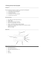
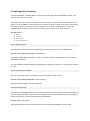
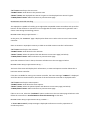
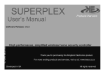
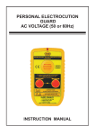
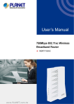
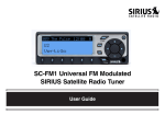
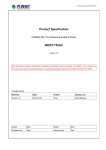
Superplex’s User’s Manual Draft CONTENTS 1. Getting to know your Superplex Package List……………………………………………………………………………………………………………….. Basic Specifications……………………………………………………………………………………………………. Appearance……………………………………………………………………………………………………………….. 2. Setting Up Your Superplex Power On/Off……………………………………………………………………………………………………………. Battery Charging………………………………………………………………………………………………………… Interface Port Connection to External Devices…………………………………………………………… 3. Exploring Quick Button Access Functions Open Menu……………………………………………………………………………………………………………….. View Events History…………………………………………………………………………………………………… Test Zone Sensors……………………………………………………………………………………………………… Panel Arm and Disarm……………………………………………………………………………………………….. 4. Exploring Menu Functions Device Memory Delete………………………………………………………………………………………………. Events History Memory Delete………………………………………………………………………………….. Zone Sensor Bypassing………………………………………………………………………………………………. New Remote Controller Enrolling………………………………………………………………………………. Enrolled Remote Controller Removing………………………………………………………………………. New Zone Sensor Enrolling………………………………………………………………………………………… Enrolled Zone Passive Removing……………………………………………………………………………….. Date/Time Configurations…………………………………………………………………………………………. Thank you for purchasing this device SUPERPLEX High Performance, simplified home security controller 1. Getting to Know Your Superplex Package List Ensure the below list of items is packed in your Superplex packaging box. 1. 1 x Superplex Security Controller unit 2. 2 x Qtron Robo remote controllers 3. 1 x AC/DC wall charger 4. 1 x Superplex User’s Manual Booklet 5. 1 x Interface Port I/O Loom Basic Specifications Size: 105mm [L] x 65mm [W] x 21mm [H] Weight: 146g Max Standby time: ap prox 72 hours Max RF link range(insight): 250 meters Display: 128 x 64 pixel graphical [Blue backlight] Interface Port: 5 x Open Collector Outputs and 1 x Common Ground 500mA max sink current 13.8V max Voltage Appearance 5 1 6 2 3 4 7 Superplex Security Controller Outline sketch 1. 2. 3. 4. 5. 6. 7. 8. UP / “Quick-Entry Zone Test” Down / “Quick-Entry Arm / Disarm” Select / “Quick-Entry Main Menu entry” Cancel or Back / “Quick-Entry Events History view” Antenna Display Charge Port Interface Port 8 2. Setting up Your Superplex Power On/Off Power on: Press any of the four buttons Power Off: Press “CANCE/BACK” button and hold. The power down countdown timer will be visible on the display and the system will shut down when it times out. Tip: Power down can be aborted by pressing the “SELECT” button while countdown timer active. Battery Charging Plug the supplied AC/DC wall charger to AC mains and insert the charger’s pin into the Superplex’s charging port. System charging graphical message is displayed. Observe the battery level icon on display; it should indicate charging in progress by horizontal lines across the icon. When charging is complete, the battery level icon will display one solid bar. Thus four battery level status bars. Tip: Always allow full charging of the battery to maximise system’s active time and battery lifespan. Interface Port Connection to External Devices The Superplex is equipped with five outputs to interface to external devices. All five outputs are open collectors designed to sink 500mA (max) and rated to function with up to 13.8V. See below diagram. Port Number Port Type Configuration Function 1 Output Open Collector Siren 2 Output Open Collector Alarm 3 Output Open Collector Panic 4 Output Open Collector Tamper/Trouble 5 Output Open Collector Status 6 Common Ground Common GND Siren Output: Interface to siren control input of an external device. Its signals are as below: Superplex arming – 1 x pulse Superplex disarming – 2 x pulses Superplex disarming while alarm had triggered – 3 x pulses Detected Alarm/Tamper/ Panic – Latch for 15sec or until alarm is silenced by user Alarm Output: Connect to external device to trigger when alarm detected. Signals are shown below: Alarm detection – Latch for 15sec or until alarm is silenced by user Panic Output: Interface to external device to trigger when Panic alarm is detected. Signals described below: Panic alarm detection – latch for 15sec or until alarm is silenced by user Tamper/Trouble output: Connect to external device to trigger when zone sensors are being tampered with or when their health status is faulted. Signals are described below: Tamper alarm detection - Latch for 15sec or until alarm is silenced by user Trouble signal detection - Latch for 15sec or until alarm is silenced by user Status Output: This port alerts the external device interfaced to it of the Superplex’s armed or disarmed status. Signals a described below: Superplex armed – Output is latched high Superplex disarmed – Output is latched low Superplex armed and has received alarm – Output pulsing until system disarm GND/Ground Connection: Connect to the external device’s ground for a return path. Tip: Care must be taken to limit the sink current of outputs. Minimal current sinking is advised to yield minimised thermal intensification. 3. Exploring Quick Button Access Functions The Superplex’s user’s buttons are designed to have more than one function command, thus a user can access multiple options depending on which level of the menu tree they’re viewing. “Quick Button Access” functions are only accessible on system’s idle menu and are described below, together with their alternating functions. Note: Ensure your Superplex is in idle menu display prior to practicing the below instructions. Open Menu The “SELECT”/”Quick Menu Entry” button is used to enter the Superplex’s Main Menu when in idle menu level. The Main Menu is the initial page of the menu tree to allow user to access features of the Superplex. Press “SELECT”/”Quick Menu Entry” button to enter Main Menu. IDLE MENU > Main Menu >……… Settings Arm/Disarm System Bypass Options Memory Management View Events History The Superplex is capable of logging real time events into its event history memory. These events are accessible to the user using the “Quick Events Entry” button. One event’s information is displayed at the time and scrolling up or down leads to viewing a previous or next event, respectively. Event view wrapping is possible after viewing the last or first event. Press “CANCEL or BACK”/”Quick Events Entry” button to enter Events View IDLE MENU > History >……… Event number Event Date – Event Time Event Type Originator’s Name Test Zone Sensors To test if enrolled zone sensors are discoverable by the Superplex, a zone test can be performed. Enter the zone test menu and walk pass the enrolled sensor to trigger intrusion alarm (NOT TAMPER). If enrolled sensor is functional and discoverable, its designated zone number and origin name will be displayed as detected. Press “UP”/”Quick Zone Test Entry” button to enter Zone Test page IDLE MENU > Zone Test >……… Searching……………… Or Detected Zone number Originator’s Name To exit and return to Idle Menu page, press “UP”/”Quick Zone Test Entry” or “CANCEL” button. Panel Arm and Disarm This function enables arming and disarming from the Superplex. Press “DOWN”/”Quick Arm/Disarm Entry” button to arm system if it’s disarmed. Press the same button to disarm system if armed. IDLE MENU > System Armed >……… Superplex is armed IDLE MENU > System Disarmed >……… Superplex is disarmed 4. Exploring Menu Functions From the Idle Menu, the Main Menu is accessed by pressing the “Quick Main Menu” button. This leads to the menu tree as below. To navigate the menu, the primary functions of the buttons are instated over the alternative. This means “UP” and “DOWN” buttons allows user to either scroll up or down in the menu, respectively. The “SELECT” button is therefore used to accept/ enter or confirm pointed option. Finally, the “CANCEL/BACK” button is used to revert to previous menu page, cancel or exit process. IDLE MENU > MAIN >……… Settings Arm/Disarm Bypass Options Memory Management Device Memory Delete This clears the entire memory of the Superplex, thus all events history and enrolled devices. IDLE MENU > MAIN > MEMORY MANAGEMENT > Erase All Memory……… A prompt message will be displayed in order to ascertain memory clearing operation. Follow the displayed instructions. Tip: The Superplex prompt messages will often refer to “CANCEL” button as “C” and “SELECT” button as “OK”. Events History Memory Delete This option will only clear all stored events and reset events counter to zero. IDLE MENU > MAIN > MEMORY MANAGEMENT > Erase Event History……… Follow prompt message to perform operation. Zone Sensor Bypassing The Superplex is equipped with the zone bypassing feature. All alarm signals from the bypassed zone sensors are ignored when system is armed. The bypass option can be individually set or cleared for each of the 32 zones. Inactive zone bypassing is prohibited. IDLE MENU > MAIN > Bypass Options……… This page displays the zone number and name to be configured including its current state. “UP” button: Scroll up to the next zone “DOWN” button: Scroll down to the previous zone “SELECT” button: Set displayed zone sensor’s bypass or clear displayed zone sensor’s bypass “CANCEL/BACK” button: Abort and return to previous menu page New Remote Controller Enrolling The Superplex is capable of enrolling up to eight Robo compatible remote controllers with up to four buttons. All four buttons on remote are user configurable and each remote can be granted a user’s choice name during the enrolling process. IDLE MENU > MAIN > Settings > Program Remotes……… At this point, the “REMOTES” page is displayed to allow user to select a slot to enrol a new remote controller. Slots are entities in Superplex’s memory to hold an enrolled remote controller’s information. “UP” button: Scroll up the slot selection “DOWN” button: Scroll down the slot selection “SELECT” button: Select the pointed slot and advance to next menu page (see below) “CANCEL/BACK” button: Abort and return to previous menu page Upon Slot selection of user’s choice, the menu will advance to the next page as below. IDLE MENU > MAIN > Settings > Program Remotes >Slot (n)……… This level of the menu will display Slot’s information, its status and options to either delete Slot or load new remote controller. If the Slot is available for storing new remote controller, the status message “>EMPTY<” is displayed and If the Slot has stored contents, the name of the stored remote controller is displayed rather. “UP” button: Scroll up the menu options “DOWN” button: Scroll down the menu options “SELECT” button: Select the pointed option and advance to next menu page (see below) “CANCEL/BACK” button: Abort and return to previous menu page If Slot is not in use, select the “Load New” option to advance to the next menu page as below or else follow the instructions in Enrolled Remote Controller Removing to clear Slot. IDLE MENU > MAIN > Settings > Program Remotes >Slot (n) > Load New……… A “Press >OK< to Start” prompt message is displayed to allow user time for preparation of enrolment process. Follow the instruction steps as displayed and note that the process can be aborted by pressing the “CANCEL/BACK” button. 1. Press “SELECT” button to initialize process. 2. Display “Waiting for Button 1” – Press the first button on remote controller to configure its function. Note: Superplex will only advance to the next step if it has received a valid Robo remote controller’s button data. 3. Select desired button function from the four displayed options. Use the “UP” or “DOWN” buttons to scroll through the options and the “SELECT” button to accept pointed selection. 4. Follow the instruction displayed. Repeat process in 2. And 3. For all four buttons. Note: Less than four buttons can be loaded if desired. This is done by pressing the “SELECT” button while the system prompts you to load a button. 5. Upon the last button being loaded or skipped as mentioned above, the system will advance to the remote naming menu page. Use “UP” or “DOWN” buttons to scroll through the characters. The character pointers indicate the pointed character and the selection is through the “SELECT” button. Selected characters are displayed on text show area on display as they’re chosen. 6. With the remote name in place, completion of the new remote controller enrolment is done by pressing the “SELECT” button and holding it down until a “Loading done” message is displayed. The new remote is stored in the selected slot. 7. To abort process at remote naming stage, press and hold “CANCEL/BACK” button until cancel message is displayed Enrolled Remote Controller Removing Enrolled user’s remote controllers are contained in Slots and can be deleted or removed individually, thus clearing the Slot. IDLE MENU > MAIN > Settings > Program Remotes >Slot (n)……… This level of the menu will display Slot’s information, its status and options to either delete Slot or load new remote controller. If the Slot is available for storing new remote controller, the status message “>EMPTY<” is displayed and If the Slot has stored contents, the name of the stored remote controller is displayed rather. “UP” button: Scroll up the menu options “DOWN” button: Scroll down the menu options “SELECT” button: Select the pointed option and advance to next menu page (see below) “CANCEL/BACK” button: Abort and return to previous menu page If the Slot contains the desired remote controller to delete select the “Erase” option to advance to the next menu page as below. IDLE MENU > MAIN > Settings > Program Remotes >Slot (n) > Erase……… A prompt message will be displayed in order to ascertain remote controller delete operation. Follow the displayed instructions. New Zone Sensor Enrolling Up to 32 zone sensors can be enrolled by the Superplex. Each zone sensor can be allocated a user defined name. See below the process to enrol new sensors. IDLE MENU > MAIN > Settings > Program Sensors……… At this point, the “SENSORS” menu page is displayed to allow user to select a zone to enrol a new zone sensor. Zones are entities in Superplex’s memory to hold an enrolled zone sensor’s information. “UP” button: Scroll up the zone selection “DOWN” button: Scroll down the zone selection “SELECT” button: Select the pointed zone and advance to next menu page (see below) “CANCEL/BACK” button: Abort and return to previous menu page Upon zone selection of user’s choice, the menu will advance to the next page as below. IDLE MENU > MAIN > Settings > Program Sensors >Zone (n)……… This level of the menu will display zone’s information, its status and options to either delete or load new zone sensor. If the zone is available for storing new a zone sensor, the status message “>EMPTY<” is displayed and If the zone has stored contents, the name of the stored zone sensor is displayed rather. “UP” button: Scroll up the menu options “DOWN” button: Scroll down the menu options “SELECT” button: Select the pointed option and advance to next menu page (see below) “CANCEL/BACK” button: Abort and return to previous menu page If the zone is not in use, select the “Load New” option to advance to the next menu page as below or else follow the instructions in Enrolled Zone Sensor Removing to clear zone. IDLE MENU > MAIN > Settings > Program Sensors >Zone (n) > Load New……… A “Press >OK< to Start” prompt message is displayed to allow user time for preparation of enrolment process. Follow the instruction steps as displayed and note that the process can be aborted by pressing the “CANCEL/BACK” button. 1. Press “SELECT” button to initialize process. 2. Display “Awaiting Tamper Code” – Trigger a tamper alarm on the sensor to be enrolled. The system will advance to the next step. Note: Superplex will only advance to the next step if it has received a valid Robo sensor’s Tamper code only. 3. At this stage the zone sensor naming menu page is displayed. Use “UP” or “DOWN” buttons to scroll through the characters. The character pointers indicate the pointed character and the selection is through the “SELECT” button. Selected characters are displayed on text show area on display as they’re chosen. 4. With the zone name in place, completion of the new zone sensor enrolment is done by pressing the “SELECT” button and holding it down until a “Loading done” message is displayed. The new zone sensor is stored in the selected zone. 5. To abort process at zone sensor naming stage, press and hold “CANCEL/BACK” button until cancel message is displayed Enrolled Zone Passive Removing Enrolled user’s zone sensors are contained in zones and can be deleted or removed individually, thus clearing the zone. IDLE MENU > MAIN > Settings > Program Sensors>Zone (n)……… This level of the menu will display zone’s information, its status and options to either delete or load new zone sensors. If the zone is available for storing new zone sensors, the status message “>EMPTY<” is displayed and If the zone has stored contents, the name of the stored zone sensor is displayed rather. “UP” button: Scroll up the menu options “DOWN” button: Scroll down the menu options “SELECT” button: Select the pointed option and advance to next menu page (see below) “CANCEL/BACK” button: Abort and return to previous menu page If the zone contains the desired zone sensor to delete, select the “Erase” option to advance to the next menu page as below. IDLE MENU > MAIN > Settings > Program Sensors >Zone (n) > Erase……… A prompt message will be displayed in order to ascertain zone sensor delete operation. Follow the displayed instructions. Date/Time Configurations Date and time can be setup by user as guided below. To setup time, navigate to the menu page as below. IDLE MENU > MAIN > Settings > Date/Time Set > Set Time……… Time in hours and minutes will be displayed. The settable time parameter is indicated by a continuous digit flash. The user buttons are used to set these parameters. “UP” button: Increment the selected parameter value “DOWN” button: Decrement the selected parameter value “SELECT” button: Accept the set parameter value and advance to the next “CANCEL/BACK” button: Abort and return to previous menu page Follow the above instructions to set the next parameter and press “SELECT” button to save and exit setup. To setup date, navigate to the menu page as below. IDLE MENU > MAIN > Settings > Date/Time Set > Set Date……… Date in DD/MM/YY configuration will be displayed. The settable date parameter is indicated by a continuous digit flash. The user buttons are used to set these parameters. “UP” button: Increment the selected parameter value “DOWN” button: Decrement the selected parameter value “SELECT” button: Accept the set parameter value and advance to the next “CANCEL/BACK” button: Abort and return to previous menu page Follow the above instructions to set the next parameters. When the last parameter value has been set, press “SELECT” button to save and exit setup.