1
SoundBrick®
1400 DS
INSTALLATION AND OPERATION MANUAL
Dual Outputs,
Same Messages
Quick install
instructions
on back cover
Please leave this manual with the unit at all times
Important warranty information enclosed
SoundBrick® 1400 DS
11/2007
TABLE OF CONTENTS
What is the SoundBrick 1400 DS? .....................................................................4
System Overview ...............................................................................................6
Front Panel ...............................................................................................6
Connections Panel ....................................................................................8
Tape Preparation Instructions ............................................................................9
Message Length Tables ...................................................................................10
Installation ........................................................................................................11
Step 1 – Set the option switches.............................................................11
Time Interval, Switches 1-2-3-4 .....................................................12
Number of Messages, Switches 5-6 ..............................................12
Bandwidth, Switch 7 ......................................................................13
Fade Level, Switch 8 .....................................................................13
Step 2 – Connections .............................................................................14
Step 3 – Load Messages ........................................................................16
Tape Load .....................................................................................16
Handset Load (Live Record) ..........................................................17
Message Select .............................................................................18
Step 4 – Adjust Volume ..........................................................................19
Playback Operation ..........................................................................................20
Timed Message Play ..............................................................................20
Manual Message Play ............................................................................20
External Trigger................................................................................................21
Diagnostics ......................................................................................................22
Wall Mounting Instructions ...............................................................................25
Technical Specifications...................................................................................26
Troubleshooting ...............................................................................................27
FCC Notice.......................................................................................................29
Limited Warranty ..............................................................................................29
Copyright Notice...............................................................................................29
Quick Install Instructions ..................................................................................32
LIST OF FIGURES
Figure 1 - Front Panel Diagram..........................................................................6
Figure 2 - Side Panel Diagram ...........................................................................8
Figure 3 - Option Select Switches ....................................................................11
Figure 4 - Installation Diagram .........................................................................14
Figure 5 - Trigger Pin Numbers (jacks on side of unit) .....................................21
LIST OF TABLES
Table 1 - Message Length @ 6.5KHz Bandwidth ............................................10
Table 2 - Message Length @ 11.5KHz Bandwidth ..........................................10
Table 3 - Option Select Switches .....................................................................11
Table 4 - Time Intervals ...................................................................................12
2
SoundBrick® 1400 DS
11/2007
Table 5 - Number of Messages ....................................................................... 13
Table 6 - Message Light Indications (Tape Load) ........................................... 16
Table 7 - External Trigger Pin Numbers and Wire Colors ............................... 21
Table 8 - Diagnostics Menu............................................................................. 22
Table 9 - Diagnostic Time Interval................................................................... 23
Table 10 - Power on Self-Test Failure Indications .......................................... 24
Table 11 - Troubleshooting ............................................................................. 28
SoundBrick® 1400 DS
3
11/2007
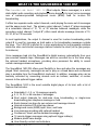
WHAT IS THE SOUNDBRICK 1400 DS?
The SoundBrick® Model 1400 DS (Dual outputs, Same messages) is a solidstate digital audio recording and playback device designed to inject voice messages
over a customer-provided background music (BGM) feed for in-store PA
broadcasting.
It offers two separate audio output channels, each playing the same set of messages
and the same music feed. The primary output channel (“output A”) plays messages
at a selectable interval of 10, 15, or 20 minutes between messages, while the
secondary output channel (“output B”) offers much shorter message intervals of 10,
20, 30, 60 or 120 seconds.
In most applications, the output A channel is used for in-store broadcasting while
output B is used for message on hold audio or for broadcasting messages outside
the store. The 1400 DS is perfect for c-store applications for long message rotations
inside the store and shorter message rotations outside the store (at the gas pumps,
for instance).
Voice messages load into the SoundBrick’s digital memory automatically from your
pre-recorded cassette tape. Messages can also be recorded live in the store using
the optional handset microphone, providing store personnel the ability to record
custom messages whenever needed.
The SoundBrick 1400 DS offers great flexibility in how and when the messages are
played. Most commonly, messages are set to play on a timed basis and on-demand
play is available from the SoundBrick’s keyboard. In addition, message play can be
remotely activated by connecting devices such as buttons, switches, or motion
sensors to the optional trigger cables.
The SoundBrick 1400 is the most versatile digital player of its kind, with a list of
features that includes:
9 Selectable 2, 4, 8, or 16 message capacity
9 4, 8, 16, 32, or 64 minutes of messages
9 Dual output channels for dual-zone store broadcasting, or single-zone
9
9
9
9
9
9
9
9
broadcasting plus telephone message on hold.
Each channel can have its own volume and message interval
Internal motorized CD-style tape drawer
Background music (BGM) input, timer, and fader
Live message recording with optional handset
Continuous, timed, and on-demand message play
16 remote-trigger messages using optional trigger cable(s)
Modern plastic case design
User-friendly controls and indicators
SoundBrick® 1400 DS
4
11/2007
9
9
9
9
9
9
Wall-mountable
Flash memory: No battery backup, no message loss due to power outages
Selectable 6.5KHz or 11.5KHz bandwidths
ADPCM 96dB signal-to-noise ratio for clear, hi-fidelity audio
Separate 8Ω and 1KΩ RCA output jacks
Built-in 2-watt amplifier
Every SoundBrick is built to exacting quality standards using state-of-the-art SMT
(surface mount) assembly for outstanding reliability and years of dependable service.
To get the best possible performance from your SoundBrick, please take the time to
read this manual and fully familiarize yourself with how the SoundBrick works before
you begin installation.
IMPORTANT NOTE
Two items must be supplied by your messaging
provider which are not included with the
SoundBrick:
1. A pre-recorded cassette tape containing the
voice messages
2. A line-level background music (BGM) source
with an RCA-style output jack.
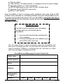
Use the space below to record information about the SoundBrick and
about your messaging provider. You will need this information should you
require assistance installing or configuring the unit, and when you need
new voice messages or background music.
SoundBrick and Messaging Provider Contact Info.
Dealer name:
Contact person:
Phone:
Address:
Serial number:
(11 digits)
Memory:
4 Min.
SoundBrick® 1400 DS
8 Min.
5
16 Min.
32 Min.
64 Min.
11/2007
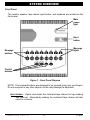
SYSTEM OVERVIEW
Front Panel
The monitor speaker, tape drawer eject button, and keyboard are located on the
front panel.
Main
power
light
Eject
button
Message
lights
Message
buttons
Control
buttons
Figure 1 - Front Panel Diagram
NOTE: The keyboard buttons are designed to be pressed using only your fingers.
Do not use pens or any other objects, as this may damage the keyboard.
Eject button – Opens and closes the motorized tape drawer for tape loading
and removal. Momentarily pushing the motorized tape drawer will also
result in a closure.
SoundBrick® 1400 DS
6
11/2007
Message buttons – The message buttons, numbered 1 through 16, are used
to specify individual messages when you select/de-select, record, or
manually play a message. In normal operation mode, pressing the
message buttons does nothing.
Message lights – Located above each message button, the message lights
indicate the status of that message.
Run/Setup button – Places the system in either run or setup mode. Run is the
normal operating mode (i.e. "running" messages and music). In setup
mode, message play stops so you can access the live record, message
select, and manual play functions. The current mode is indicated by the
lights on top of the button: Run (light on right) or Setup (light on left).
Play/Record button – Selects the play and live record functions. Play is used
to manually play a message over the sound system. Record is used to
record live messages with the optional handset. Recording can only be
performed in Program mode. The current mode is indicated by the lights
on top of the button: Play (light on left) or Record (light on right).
Message select button - Lets you select which loaded messages to play (and
not play) over the sound system.
Monitor button – Not used on the 1400 DS. The unit does not contain an
internal monitor speaker.
SoundBrick® 1400 DS
7
11/2007
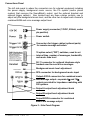
Connections Panel
The left side panel is where the connectors are for external equipment including
the power supply, background music source, the PA system (and/or phone
system) that receives the SoundBrick's output, and the optional handset and
external trigger cable(s). Also located here are three volume controls, one to
adjust only the background music level, and the other two to adjust each channel’s
combined BGM and voice message output level.
Power supply connector (12VDC, 500mA, center
pin positive)
Power switch
Connectors for trigger cables (optional parts)
for remote message activation
10 option select (“DIP”) switches, used to set
interval time, number of messages, bandwidth,
and music fade level
RJ-11 connector for optional telephone-style
handset used to record live messages
Background music level adjustment
RCA connector for background music input
Output A RCA connectors for combined music
and message output—separate 8Ω and 1KΩ
outputs provided for impedance matching with
PA systems.
Output A output level adjustment knob
Output B output level adjustment knob
Output B RCA connector for combined
music and message output
Figure 2 - Side Panel Diagram
SoundBrick® 1400 DS
8
11/2007
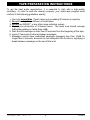
TAPE PREPARATION INSTRUCTIONS
To get the best audio reproduction, it is essential to start with a high-quality
recording. In order to load into memory properly, your audio tape program must
conform to the following guidelines exactly.
1.
2.
3.
4.
Use only normal bias (Type I) tapes not exceeding 90 minutes in capacity.
Do not use high bias, chrome, or metal tapes.
Do not use DOLBY® or any other noise reduction system.
Record your production in 2-channel mono. The audio level should average
0dB while peaking no hotter than +6dB.
5. Start the first message no later than 20 seconds from the beginning of the tape.
6. Leave 15 seconds of silence between messages.
7. Messages cannot have embedded passages averaging less than -25dB for
longer than 5 seconds, because the unit interprets this as silence, signifying a
break between messages or the end of the load.
SoundBrick® 1400 DS
9
11/2007
MESSAGE LENGTH TABLES
Message length is determined by three factors: the memory size of your unit, the
bandwidth setting, and the number of messages setting. It is very important that no
message on your tape is longer than this time, because during tape load the
message will spill into the next message slot, resulting in cut off, split, and/or missing
messages upon playback.
Refer to the following tables to find your maximum message length. Use Table 1 for
6.5KHz bandwidth or Table 2 for 11.5KHz bandwidth.
Memory Equipped
Number of
Messages
4 min.
8 min.
16 min.
32 min.
64 min.
2
2 min.
4 min.
8 min.
16 min.
32 min.
4
1 min.
2 min.
4 min.
8 min.
16 min.
8
30 sec.
1 min.
2 min.
4 min.
8 min.
16
14 sec.
30 sec.
1 min.
2 min.
4 min.
Table 1 - Message Length @ 6.5KHz Bandwidth
Memory Equipped
Number of
Messages
4 min.
8 min.
16 min.
32 min.
64 min.
2
1 min.
2 min.
4 min.
8 min.
16 min.
4
30 sec.
1 min.
2 min.
4 min.
8 min.
8
15 sec.
30 sec.
1 min.
2 min.
4 min.
16
7 sec.
15 sec.
30 sec.
1 min.
2 min.
Table 2 - Message Length @ 11.5KHz Bandwidth
SoundBrick® 1400 DS
10
11/2007
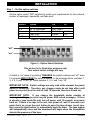
INSTALLATION
Step 1 – Set the option switches
Set the option select “DIP” switches to match your requirements for time interval,
number of messages, bandwidth, and fade level.
Switch
1, 2, 3, 4
5, 6
7
8
9, 10
Option
On
Off
Time interval
See Table 4
No. of messages
See Table 5
Bandwidth
11.5 KHz 6.5 KHz
Fade level
Partial
Full
Not used
Table 3 - Option Select Switches
“off”
“on”
Figure 3 - Option Select Switches
This picture is for illustrative purposes only.
Your actual switch settings will vary.
A switch is “on” when it is pointing TOWARDS the switch numbers and “off” when
it is pointed AWAY FROM the switch numbers. In the example above, switches 1,
2, 4, 8, 9, and 10 are “on” while switches 3, 5, 6, and 7 are “off.”
IMPORTANT NOTE: Switch settings are only read at the moment the power
switch is turned on. Therefore, any changes made do not take effect until
power is recycled (turn the unit off, wait 10 seconds, then turn it back on).
IMPORTANT NOTE: If you change the bandwidth and/or number of
messages settings, you must recycle power AND reload messages. If there
is already a tape inside the unit, turn off power, wait 10 seconds, turn power
back on. If there is no tape in the unit, turn power off, wait 10 seconds, turn
power back on, press the eject button to open the tape drawer, insert tape,
then press the eject button, or momentarily push the draw. The tape drawer
will automatically close and the download will begin when the SoundBrick
detects the presence of the tape.
SoundBrick® 1400 DS
11
11/2007
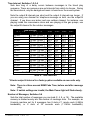
Time Interval, Switches 1-2-3-4
Sets how long of a delay occurs between messages in the timed play
sequence. There are numerous pre-set intervals from which to choose. During
the time interval, only the background music is heard over the sound system.
Note the output B intervals are short and the output A intervals are longer. If
you are using one channel for telephone message on hold, use the output B
channel. If you have one indoor and one outdoor channel, for instance, one
playing inside the convenience store and one playing at the gas pumps, use
the output B channel for the outdoor messages.
Time Interval
Output B
Output A
SW1 SW2
10 sec.
10 min. (5 min.*) OFF OFF
20 sec.
10 min. (5 min.*) ON
OFF
30 sec.
10 min. (5 min.*) OFF ON
1 min.
10 min. (5 min.*) ON
ON
2 min.
10 min. (5 min.*) OFF OFF
10 sec.
15 min. (10 min.*) ON
OFF
20 sec.
15 min. (10 min.*) OFF ON
30 sec.
15 min. (10 min.*) ON
ON
1 min.
15 min. (10 min.*) OFF OFF
2 min.
15 min. (10 min.*) ON
OFF
10 sec.
20 min. (15 min.*) OFF ON
20 sec.
20 min. (15 min.*) ON
ON
30 sec.
20 min. (15 min.*) OFF OFF
1 min.
20 min. (15 min.*) ON
OFF
2 min.
20 min. (15 min.*) OFF ON
Invalid-not used
ON
ON
Table 4 - Time Intervals
SW3
OFF
OFF
OFF
OFF
ON
ON
ON
ON
OFF
OFF
OFF
OFF
ON
ON
ON
ON
SW4
OFF
OFF
OFF
OFF
OFF
OFF
OFF
OFF
ON
ON
ON
ON
ON
ON
ON
ON
* Shorter output A interval is a factory option available on new units only.
Note: There is a three second BGM Fade Time, before and after message
play.
Note: If switch settings are invalid, the Main Power light will flash slowly.
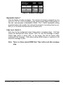
Number of Messages, Switches 5-6
Sets the total number of messages you can load (2, 4, 8, or 16). The available
memory is divided evenly into this number of message slots. For example, an
8-minute machine set for 8 messages has 8 slots of 1 minute each (6.5KHz
bandwidth), or 8 slots of 30 seconds each (11.5KHz bandwidth).
SoundBrick® 1400 DS
12
11/2007
Number of
SW5
SW6
Messages
2
OFF
OFF
4
OFF
ON
8
ON
OFF
16
ON
ON
Table 5 - Number of Messages
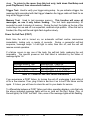
Bandwidth, Switch 7
Sets the fidelity of audio messages. The minutes of memory equipped on your
unit (4, 8, 16, 32, or 64) is printed on the serial number label on the bottom of
the unit, and assumes a bandwidth 6.5KHz. The 11.5KHz bandwidth setting
provides better audio quality, but reduces the amount of recording time by onehalf (i.e. a 16 minute unit becomes an 8 minute unit).
Fade Level, Switch 8
Sets how far the background music fades when a message plays. Full fade
lowers the background music volume 100% so only the message is heard.
Partial fade lowers it about 90%, so the music can still be heard softly
underneath the message. With either setting, BGM volume is restored to full
when the message is over.
Note: There is a three second BGM Fade Time, before and after message
play.
SoundBrick® 1400 DS
13
11/2007
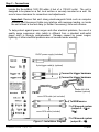
Step 2 – Connections
Locate the SoundBrick 1400 DS within 6 feet of a 110VAC outlet. The unit is
designed to be placed on a flat, level surface or securely mounted on a wall. Be
sure to leave clearance for connections and adjustments.
Important: Devices that emit strong electromagnetic fields such as computer
monitors and fluorescent lights may interfere with message loading, so locate
the unit at least a few feet away (or farther if necessary) from such devices.
To help protect against power surges and other electrical problems, the use of a
quality surge suppressor strip (which is different from a standard multi-outlet
power strip) is strongly recommended. Damage caused by power surges,
lightning, or other electrical problems are not covered under warranty.
12VDC power supply (included)
9-pin trigger cable(s) (optional)
⎝ Connect to trigger hardware
⎝ Connect to trigger hardware
Walker W-3-K-M
handset (optional)
mono RCA cable (not included)
⎝ To BGM source
mono RCA cable (included)
Figure 4 - Installation Diagram
SoundBrick® 1400 DS
14
⎝ To PA/sound system
(output A – 8Ω or
1KΩ )
⎝ To PA/sound system
(output B – 8Ω)
11/2007
Connection Instructions:
1. Turn the power switch off. Plug the included power supply into a surgeprotected 110VAC wall outlet and the 12VDC jack on the SoundBrick. Only
use the power pack provided with the unit (12VDC, 500ma, center pin positive).
Many power supplies look alike, but provide different output. Using the wrong
one will void your warranty and may damage the unit and/or other equipment
attached to the SoundBrick.
2. Connect either the 8Ω or 1KΩ output A jack to the PA sound system input using
a mono RCA-to-RCA cable (included). If the sound system does not have an
RCA-style input, an adapter may be required (not included). Remember,
output A has the long time intervals.
3. Connect the 8Ω output B jack to the outdoor channel (if applicable) on the
PA/sound system, or to the phone system’s message on hold input using a
mono RCA-to-RCA cable (included). If the PA or phone system does not have
an RCA-style input, an adapter may be required (not included). Remember,
output B has the short time intervals.
4. Connect the BGM input jack to your background music source using another
mono RCA-to-RCA cable (not included). For proper operation, the background
music source should have a low impedance output. If the BGM source does not
have an RCA-style output, an adapter may be required (not included).
5. Connect the optional handset to the handset jack if you are using this feature.
For proper operation, you must use the Walker model W3-K-M, available from
your messaging provider or from Walker Equipment Corporation, 4009 Cloud
Springs Road, Ringgold, GA 30736. Do not use an ordinary handset from your
telephone, as this will result in a weak recording.
6. Connect the optional 9-pin trigger cable(s) to the external trigger jack(s) if you
are using this feature.
SoundBrick® 1400 DS
15
11/2007
Step 3 – Load Messages
Messages can be loaded into the SoundBrick 1400 from a cassette tape, the
optional handset, or a combination of both.
Be sure you have reviewed the tape preparation instructions on
page 9.
NOTE: If you are loading both tape and handset messages, it is important to load
the tape first, because all message memory is automatically erased whenever a
tape load begins.
Tape Load
Make sure the option select switches for number of messages and bandwidth
are set to match the contents of your tape. This is especially important if you
are loading a new tape over an existing set of messages, because the new
tape might have a different number of messages, or messages of a different
length.
Turn the power switch on and press the tape eject button. The motorized tape
drawer on the right side of the unit opens like a CD-ROM drive on a computer.
Place the tape into the drawer by gently sliding it under the metal retaining clip,
then press the eject button, or momentarily push the drawer to close. The
SoundBrick detects the presence of the tape, switches itself to setup mode,
and begins the load process automatically. NOTE: Never eject the tape
while it is loading.
During tape load, the lights above the numbered message buttons display the
load progress:
Message Light
Status
Slow flash
Next message loads here
Fast flash
Message loading now
On (no flash)
Message finished loading
Off
Message empty
Table 6 - Message Light Indications (Tape Load)
Once the unit detects audio on the tape, it begins loading message #1, and
continues until it detects 15 seconds of silence, then starts loading message
#2, and so on until either 25 seconds of silence is detected or the number of
messages you set have been loaded, whichever comes first. At that point, the
tape rewinds and the unit automatically switches to Run mode and begins
playing the messages.
SoundBrick® 1400 DS
16
11/2007
If the messages are cut off, split, or missing upon playback, chances are that
the tape messages are too long to fit into the message slots, In this case, refer
to the message length tables and option select switch information earlier in this
manual, or contact your messaging provider to find the proper switch settings
for your tape.
Important: It is not necessary to leave the tape in the unit after
loading. Since the SoundBrick uses non-volatile Flash memory,
messages are not erased during power outages or when the unit is
unplugged or turned off. If you do decide to remove the tape,
LEAVE IT OUT. Every time you insert a tape with the power switch
on, all messages (tape and handset) are erased and the tape load
process begins.
Handset Load (Live Record)
After loading the tape, you can record messages using the optional handset.
As mentioned earlier, make sure you use the Walker Equipment Corp. model
W3-K-M, not an ordinary handset from your phone.
While handset-loaded messages are safe from erasure due to power loss, they
are erased each time a tape is loaded, and must be recorded again if you want
them to play. Handset messages are not copied to the tape. Additionally,
handset-loaded messages are not automatically added to the timed play
sequence. After recording, you must manually add them using message
select.
1. Press the Run/Setup button until the Setup light is on.
2. Press the Play/Record button until the Record light is on. The message
lights indicate which messages are already loaded (light on) and which
are empty (light off).
3. Press the message button that you wish to record. Recording begins as
soon as the message light starts flashing (approximately 1 second).
During recording, the message light flashes slowly. If it does not, then
you have selected a message higher than your number of messages
setting and must choose another.
4. When you are finished recording, press the message button again. If you
exceed the available message time, recording stops automatically.
To record more messages, follow steps 2-4 above. When you are finished,
proceed to message select.
Note: Because there is no Monitor Select, messages can not be
reviewed from the handset.
17
SoundBrick® 1400 DS
11/2007
Message Select
Message select lets you add and remove messages from the timed playback
sequence. All tape-loaded messages are automatically selected for playback,
while handset messages must be selected manually.
1. If the Setup light is not already on, press Run/Setup until it turns on.
2. Press the Message Select button until that light turns on. The message
lights indicate the selection status of each message: Light on (selected)
or light off (not selected or message empty).
3. Press a message button to change its selection status.
When you are finished, press the Message Select button until the light turns off,
then press Run/Setup to return to Run mode.
SoundBrick® 1400 DS
18
11/2007
Step 4 – Adjust Volume
After installation and loading is complete, listen to the SoundBrick 1400's output
over each channel separately. Adjust the BGM level and output A & B level knobs
on the left side panel as needed.
SoundBrick® 1400 DS
19
11/2007
PLAYBACK OPERATION
Timed Message Play
Music and messages play back over your sound system according to how the unit
is configured. Selected messages play in numerical order, starting with message
#1, at the time interval you set. Output B has short time intervals, output A has
long time intervals. Between messages the background music is heard. This
timed message play is the typical mode of operation. Triggered messages play
when activated (see External Trigger section for details).
Manual Message Play
Manual play messages always play out of output A.
Messages can be played on demand, using the manual message play function.
Manual message play is not available if a message is already playing - you must
wait until the unit is between messages (i.e. during the time interval).
1. If the Run light is not already on, press Run/Setup until it turns on.
2. Press the Play/Record switch until the Play light is on. Message lights turn
on for all loaded messages.
3. Press the message you want to play.
Repeat steps 2 and 3 for each message you want to play. When you are finished,
no action is required. The Play light turns off automatically and the unit returns to
timed message play where it left off.
SoundBrick® 1400 DS
20
11/2007
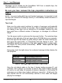
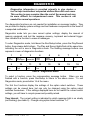
EXTERNAL TRIGGER
Triggered messages always play out of output A.
The external trigger function lets you activate any or all messages remotely by using
one or two optional 9-pin trigger cables, available from your messaging provider. An
unwired 9-pin DIN plug is also available
One end of the trigger cable plugs into the SoundBrick’s connections panel (Trigger
1-8 and/or Trigger 9-16). The other end contains 8 color-coded wire leads and one
ground lead. Message play is triggered by shorting a message's lead wire to ground.
The table below shows which message is activated by each color wire.
Wire Color (Pin Number)
Trigger 1-8
Trigger 9-16
9
Brown (1)
1
Blue (2)
2
Purple (3)
3
10
11
Red (4)
4
12
Green (5)
5
13
Orange (6)
6
14
Yellow (7)
7
15
Message
number
triggered
White (8)
8
16
Ground-silver (9)
Table 7 - External Trigger Pin Numbers and Wire Colors
Triggered messages start immediately if no message is currently playing, or after the
current message is finished. Multiple triggers are queued and played back in
message number order, which is not necessarily the order triggered. The pin
numbers on the unit’s trigger jacks are as follows:
3
7
8
(ground)
4
1
2
5
6
Figure 5 - Trigger Pin Numbers (jacks on side of unit)
SoundBrick® 1400 DS
21
11/2007
DIAGNOSTICS
Diagnostics information is provided primarily to give dealers a
tool to help troubleshoot suspected malfunctions with end users.
This section is more complex than the rest of the manual and may
be more difficult for inexperienced users. This section is not
needed for normal operations.
The diagnostics functions are not needed for installation or message loading. They
are provided to display system settings and test hardware components in the event of
a suspected malfunction.
Diagnostics mode lets you view current option settings; display the amount of
memory equipped; and test the message memory, keyboard and external trigger.
Also included is a function to erase all messages.
To enter Diagnostics mode, hold down the Run/Setup button, press the Play/Record
button, then release both buttons. The Play and Record lights flash at the same time,
indicating the unit is now in Diagnostics mode. The flashing message buttons now
represent a menu of diagnostics functions:
1
Time
Interval
9
Memory
Size
2
3
4
No. of
Messages
Bandwidth
10
11
Keypad
Test
Trigger
Test
5
Fade
Level
6
7
8
14
15
16
Erase
Messages
12
13
Memory
Test
Exit
Table 8 - Diagnostics Menu
To select a function, press the corresponding message button. When you are
finished with a function, press Run/Setup to return to the above menu. To exit
Diagnostics mode, press button 16 at the menu.
The first four functions display the settings of the option select switches. These
settings can be viewed here, but can only be changed using the option select
switches themselves. If the settings displayed here do not match the current switch
settings, you will have to recycle power and possibly reload.
Time Interval: The current setting is indicated by which message light is on steady
(not flashing) (see table 9). Change using option select switches 1-4.
SoundBrick® 1400 DS
22
11/2007
Message
Time Interval
Light
Output B
Output A
1
10 sec.
10 min. (5 min.*)
2
20 sec.
10 min. (5 min.*)
3
30 sec.
10 min. (5 min.*)
4
1 min.
10 min. (5 min.*)
5
2 min.
10 min. (5 min.*)
6
10 sec.
15 min. (10 min.*)
7
20 sec.
15 min. (10 min.*)
8
30 sec.
15 min. (10 min.*)
9
1 min.
15 min. (10 min.*)
10
2 min.
15 min. (10 min.*)
11
10 sec.
20 min. (15 min.*)
12
20 sec.
20 min. (15 min.*)
13
30 sec.
20 min. (15 min.*)
14
1 min.
20 min. (15 min.*)
15
2 min.
20 min. (15 min.*)
16
Invalid-not used
Table 9 - Diagnostic Time Interval
* Shorter output A interval is a factory option available on new units only.
Number of Messages: The current setting is indicated by which message light (2,
4, 8, or 16) is on steady (not flashing). Change using Option Select Switches 5-6.
Bandwidth: Message light 1 on steady, not flashing (6.5KHz). Message light 11
on steady, not flashing (11.5KHz). Change using Option Select Switch 7.
Fade Level: Message light 1 flashing plus message light 9 on steady=partial fade.
Message light 1 on steady plus message light 9 flashing=(full fade). Change using
Option Select Switch 8.
Erase Messages: Erases all messages (tape and handset) in memory.
Memory Size: Displays how much memory the unit has. One message light turns
on for each 4 minutes of memory. Multiply the highest number lit by 4:
Button 1 = 4 min. @ 6.5KHz (or 2 min. @ 11.5KHz)
Button 2 = 8 min. @ 6.5KHz (or 4 min. @ 11.5KHz)
Button 4 = 16 min. @ 6.5KHz (or 8 min. @ 11.5KHz)
Button 8 = 32 min. @ 6.5KHz (or 16 min. @ 11.5KHz)
Button 16 = 64 min. @ 6.5KHz (or 32 min. @ 11.5KHz)
Keypad Test: Used to verify that all buttons on the keyboard are working properly.
Press any button and that button's light will turn on for as long as the button is held
23
SoundBrick® 1400 DS
11/2007
down. To return to the menu from this test only, hold down Run/Setup and
push Play/Record, then release both buttons.
Trigger Test: Used to verify your trigger wiring setup. As you activate a trigger, the
message light associated with that trigger's lead on the trigger cable will flash for as
long as the trigger is held.
Memory Test: Used to test message memory. This function will erase all
messages, so use it only before loading. The test lasts approximately 30
seconds for each 4 minutes of memory. During the test, the lights on the top of the
control keys turn on and off in a sequential, racetrack-style pattern. When the test is
finished, the Play and Record lights flash together slowly.
Power On Self-Test (POST)
Each time the unit is turned on, an automatic self-test routine commences
immediately, lasting only a couple of seconds. During a successful self-test
sequence, message lamps 1-4 will light in order, then turn off, and the unit will
resume normal operation.
If a failure occurs in any one of the tests, the self-test halts, rendering the unit
inoperable. The specific power-on test that failed is indicated by the status of
message lights 1-4:
Self-Test Procedure
Failure Indication
Message Memory Test
Message light 1 stays on.
Audio Processor Test
Message lights 1 & 2 stay on.
Audio Processor Program
Message lights 1, 2, & 3 stay on.
Tape Deck Test
Message lights 1, 2, 3, & 4 stay on.
Table 10 - Power on Self-Test Failure Indications
If you experience a POST failure, try turning the unit off, unplugging it and letting it
sit for a few minutes. Then, plug it back in and turn it on to see if the failure occurs
again. If it does, you will have to return the unit to your dealer for service.
To differentiate between a POST failure and other operating displays, note that only
the above indicated message lights will be on (and not the Run, Setup, Play, or
Record lights) if a POST test fails. Also, none of the message lights will be flashing.
SoundBrick® 1400 DS
24
11/2007
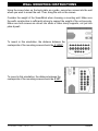
WALL MOUNTING INSTRUCTIONS
Using the screw holes on the back plate as a guide, secure two screws into the wall
where you want to mount the unit. Then, hang the unit on the screws.
Consider the weight of the SoundBrick when choosing a mounting wall. Make sure
the wall’s construction is sufficiently strong to support the weight of the unit securely.
Make sure both screws are driven into studs or other sturdy supports, not just into
plain drywall.
To mount in this orientation, the distance between the
centerpoints of the mounting screws should be 3 11/32”.
To mount in this orientation, the distance between the
centerpoints of the mounting screws should be 5 3/8”.
SoundBrick® 1400 DS
25
11/2007
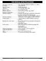
TECHNICAL SPECIFICATIONS
Frequency response.................... User-selectable 200Hz to 6.5KHz or 11.5KHz
Encoding ..................................... 16-bit ADPCM
Signal to noise ............................. 96 dB (theoretical)
Distortion ..................................... <1% THD @ 1KHz, 0dB
Memory type................................ Non-volatile FLASH
Memory capacity ......................... 4, 8, 16, 32, or 64 min. @ 6.5KHz
Number of messages .................. 2, 4, 8, or 16
Message loading ......................... Cassette (normal bias) using built-in tape deck,
Handset—Walker W3-K-M (optional),
Signal-level source using ProAdapter (optional)
Message playback....................... Continuous, timed, triggered, and on demand
Power supply ............................... 110VAC 60Hz to 12VDC 500mA, center pin
positive
Background music input .............. Mono RCA jack for low-impedance background
music source
Adjustable volume
Audio output ................................ Mono RCA jack for combined message and
music output
Adjustable volume
Output A impedance.................... 6.0V p-p @ 8Ω or 12V p-p @ 1KΩ
Output B impedance.................... 6.0V p-p @ 8Ω
Size ............................................. 8.5" x 7.5" x 3" (H x W x D)
Weight ......................................... 3.5 pounds (excluding power supply)
SoundBrick® 1400 DS
26
11/2007
TROUBLESHOOTING
If you have trouble installing or operating the SoundBrick 1400, refer to the table
below to help find a solution. If you are unable to solve the problem yourself, contact
your dealer for further assistance.
Problem or
Indication
Cut-off, split, or
missing messages
Tape load error
(run + setup lights
flashing together)
No background
music
No messages
Tape drawer won’t
open
Tape stuck in deck
or deck is “eating”
tapes
When adjusting the
output level, the
background music
level also changes
Doesn’t trigger
No power-main
power light is off
Possible Cause and Solution
Messages too long for configuration – see message
length tables. Adjust switch settings (bandwidth, number
of messages) and reload tape.
Tape is worn out or not prepared to guidelines – obtain
another tape from your messaging provider.
Possible interference from strong electromagnetic field
(i.e. computer monitor or fluorescent lights) – relocate
unit away from source of interference.
Check background music equipment and wiring.
Adjust BGM level knob.
May be in time interval – check option select switches
1-4. Output A has very long time intervals of 10, 15, or
20 minutes between messages.
Adjust output level A & B knobs.
Make sure unit is in run mode and not setup or
diagnostics mode.
Check PA system or speakers.
Make sure messages are selected for play.
If the drawer doesn’t open when you press the eject
button, press eject again.
Never eject tape during download. Follow proper tape
load procedure.
To remove stuck tape: Turn power off, wait 10
seconds, turn power on. Wait for deck to disengage play
head before ejecting.
The output level knob adjusts the background music
level at the same time as it adjusts the voice message
level. Adjust both knobs until the combined message
and music output is to your liking.
Check trigger wiring
Check the power switch. (should be on)
Check power pack for correct DC output voltage &
current.
Check power outlet to make sure it is not controlled by a
switch.
SoundBrick® 1400 DS
27
11/2007
Problem or
Indication
Main Power light
flashes slowly
Possible Cause and Solution
Invalid operation: Wrong option switch settings. Refer
to option switch settings on pages 11&12.
Table 11 - Troubleshooting
SoundBrick® 1400 DS
28
11/2007
FCC Notice
WARNING: This equipment has been tested and found to comply with the limits for a Class A digital device
pursuant to Part 15 of FCC Rules. These limits are designed to provide reasonable protection against
harmful interference when this equipment is operated in a commercial environment. This equipment
generates, uses, and can radiate radio frequency energy and, if not installed and used in accordance with
the instruction manual, may cause harmful interference to radio communications. Operation of this
equipment in a residential area is likely to cause harmful interference in which case the user will be required
to correct the interference at his/her own expense.
This digital apparatus does not exceed the Class A limits for radio noise emissions from digital
apparatus set out in the Radio Interference Regulations of the Canadian Department of Communications.
Le présent appareil numérique n'émet pas de bruits radioélectriques dépassant les limites
applicables aux appareils numériques de la Class A prescrites dans le Règlement sur le brouillage
radioélectrique édicté par le ministère des Communications du Canada.
Limited Warranty
TERMS: Nel-Tech warrants to the original purchaser ("Buyer") that the Product sold is free from
defects in material and workmanship at the time of purchase. The warranty extends five (5) years
from the date of original purchase and covers parts and labor. Buyer must provide written notice to
Nel-Tech within the warranty period of any defective part or conditions. If the defect is not the result
of improper use, service, maintenance or installation, and if the equipment has not been otherwise
damaged or modified after shipment, Nel-Tech or its authorized representative shall either replace
or repair the defective Product at Nel-Tech's option. No credit shall be allowed for work performed
by Buyer or unauthorized parties. Out-of-warranty repairs will be invoiced at the current Nel-Tech
hourly rate plus the cost of parts, shipping and handling. IN THE EVENT THAT THE PRODUCT
SERIAL NUMBER IS MISSING OR HAS BEEN TAMPERED WITH IN ANY WAY, THE
FOREGOING WARRANTY IS VOID AND WITHOUT EFFECT AND NEL-TECH SHALL HAVE NO
LIABILITY WHATSOEVER ON ACCOUNT OF DEFECTS TO SUCH PRODUCT.
LIMITATIONS: EXCEPT AS STATED ABOVE, THERE ARE NO WARRANTIES, EXPRESS OR
IMPLIED, THAT EXTEND BEYOND THE SPECIFICATIONS FOR THE PRODUCT. NEL-TECH
EXPRESSLY DISCLAIMS ANY WARRANTY, EXPRESS OR IMPLIED, THAT EQUIPMENT SOLD
HEREUNDER IS OF MERCHANTIABLE QUALITY OR THAT IT CAN BE USED, OR IS FIT FOR
ANY PARTICULAR PURPOSE. BUYER PURCHASES AND ACCEPTS EQUIPMENT SOLELY
ON THE BASIS OF THE WARRANTY HEREINABOVE EXPRESSED.
UNDER NO
CIRCUMSTANCES SHALL NEL-TECH BE LIABLE BY VIRTUE OF THIS WARRANTY OR
OTHERWISE FOR ANY SPECIAL, INDIRECT, SECONDARY OR CONSEQUENTIAL DAMAGES
TO ANY PERSON OR PROPERTY ARISING OUT OF THE USE OR INABILITY TO USE THE
PRODUCT.
REPAIRING OR REPLACING PRODUCT: Buyer may obtain the repair or replacement of any
eligible part or equipment covered under this warranty through Nel-Tech only. Buyer is responsible
for all shipping and handling charges in connection with the performance of this warranty. Products
returned to Nel-Tech must be securely packaged to prevent damage in transit, freight prepaid, and
insured for replacement value. A return authorization number assigned by Nel-Tech must be
clearly marked on the outside of the shipping container. Proof of purchase must accompany
shipment. Items delivered to Nel-Tech without a return authorization clearly marked on the outside
of the shipping container, and/or without proof of purchase will be refused. Please contact NelTech at the address and phone number below to receive a return authorization number and to
arrange for the repair or replacement of a flawed part covered by this warranty. Please indicate the
Product's serial number in all correspondence. an authorization number will not be issued in the
absence of a serial number. Nel-Tech Labs, Inc., 4 Ash Street Extension, Derry, NH 03038, Phone:
(603) 425-1096.
Copyright Notice
This manual Copyright © 1984 – 2008 by Nel-Tech Labs, Inc. All rights reserved. No part of it may
be copied, photocopied, reproduced, translated, or reduced to any electronic medium or
machine-readable form without Nel-Tech's prior written consent.
Information contained herein is subject to change without prior notification. Nel-Tech Labs, Inc.
provides this manual without warranty of any kind, express or implied. This user's manual may
contain technical and/or typographical errors.
SoundBrick is a registered trademark of Nel-Tech Labs, Inc.
Printed in the U.S.A.
SoundBrick® 1400 DS
29
11/2007
This page intentionally left blank.
SoundBrick® 1400 DS
30
11/2007
This page intentionally left blank.
SoundBrick® 1400 DS
31
11/2007
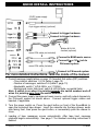
QUICK INSTALL INSTRUCTIONS
12VDC power supply
(included)
9-pin trigger cable(s) (optional)
⎝ Connect to trigger hardware
⎝ Connect to trigger hardware
Walker W-3-K-M
handset (optional)
mono RCA cable (not included)
⎝ Connect to BGM music source
⎝ Connect 8Ω or 1KΩ jack to
PA/sound system
mono RCA cable (included)
⎝ Connect to PA/sound system
For more detailed instructions, read the inside of the manual.
1. Consult message length tables on page 10 if needed. Set option (DIP) switches:
--Time interval, switches 1-2-3-4 (table 4, page 12)
--Number of messages, switches 5-6 (table 5, page 13)
--Bandwidth, switch 7 (off=6.5KHz, on=11.5KHz)
--Background music fade level, switch 8 (off=full fade, on=partial fade)
Note: A switch is on when it is pointing towards the switch numbers and off
when it is pointing away from the switch numbers.
2. Connect the power supply, background music source, and both output channels to
the PA/sound system as shown above. Connect optional trigger cables and
handset, if applicable.
3. Turn the power switch on. Press the eject button on front of the SoundBrick to
open the motorized tape drawer. Insert the cassette into the tape drawer, audio
side facing front, then press the eject button, or momentarily push the drawer to
close.
4. Loading of tape messages occurs automatically. After tape load, message
playback begins automatically. See page 17 for handset recording instructions if
desired.
SoundBrick® 1400 DS
32
11/2007