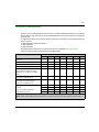
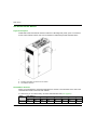
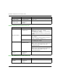
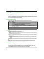
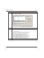
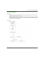
1
Modicon M580 EIO0000001578 09/2014 Modicon M580 Hardware Reference Manual EIO0000001578.02 09/2014 www.schneider-electric.com The information provided in this documentation contains general descriptions and/or technical characteristics of the performance of the products contained herein. This documentation is not intended as a substitute for and is not to be used for determining suitability or reliability of these products for specific user applications. It is the duty of any such user or integrator to perform the appropriate and complete risk analysis, evaluation and testing of the products with respect to the relevant specific application or use thereof. Neither Schneider Electric nor any of its affiliates or subsidiaries shall be responsible or liable for misuse of the information contained herein. If you have any suggestions for improvements or amendments or have found errors in this publication, please notify us. No part of this document may be reproduced in any form or by any means, electronic or mechanical, including photocopying, without express written permission of Schneider Electric. All pertinent state, regional, and local safety regulations must be observed when installing and using this product. For reasons of safety and to help ensure compliance with documented system data, only the manufacturer should perform repairs to components. When devices are used for applications with technical safety requirements, the relevant instructions must be followed. Failure to use Schneider Electric software or approved software with our hardware products may result in injury, harm, or improper operating results. Failure to observe this information can result in injury or equipment damage. © 2014 Schneider Electric. All rights reserved. 2 EIO0000001578 09/2014 Table of Contents Safety Information . . . . . . . . . . . . . . . . . . . . . . . . . . . . . About the Book. . . . . . . . . . . . . . . . . . . . . . . . . . . . . . . . Part I Hardware Elements in the Modicon M580 Local Rack . . . . . . . . . . . . . . . . . . . . . . . . . . . . . . . . . . . . . Chapter 1 M580 CPUs . . . . . . . . . . . . . . . . . . . . . . . . . . . . . . . . . . . 1.1 BME P58 xxxx CPU Functional Characteristics . . . . . . . . . . . . . . . . . Introduction . . . . . . . . . . . . . . . . . . . . . . . . . . . . . . . . . . . . . . . . . . . . . Performance Characteristics . . . . . . . . . . . . . . . . . . . . . . . . . . . . . . . . Operating States . . . . . . . . . . . . . . . . . . . . . . . . . . . . . . . . . . . . . . . . . Electrical Characteristics . . . . . . . . . . . . . . . . . . . . . . . . . . . . . . . . . . . Real-Time Clock . . . . . . . . . . . . . . . . . . . . . . . . . . . . . . . . . . . . . . . . . Addressing Field Buses . . . . . . . . . . . . . . . . . . . . . . . . . . . . . . . . . . . . 1.2 BME P58 xxxx CPU Physical Characteristics . . . . . . . . . . . . . . . . . . . Position and Dimensions . . . . . . . . . . . . . . . . . . . . . . . . . . . . . . . . . . . Front Panel . . . . . . . . . . . . . . . . . . . . . . . . . . . . . . . . . . . . . . . . . . . . . LED Indications . . . . . . . . . . . . . . . . . . . . . . . . . . . . . . . . . . . . . . . . . . USB Port . . . . . . . . . . . . . . . . . . . . . . . . . . . . . . . . . . . . . . . . . . . . . . . Ethernet Ports . . . . . . . . . . . . . . . . . . . . . . . . . . . . . . . . . . . . . . . . . . . Connecting an M580 Device Network to the Control Network . . . . . . SD Memory Card . . . . . . . . . . . . . . . . . . . . . . . . . . . . . . . . . . . . . . . . . Memory Card Access LED . . . . . . . . . . . . . . . . . . . . . . . . . . . . . . . . . Firmware Upgrade. . . . . . . . . . . . . . . . . . . . . . . . . . . . . . . . . . . . . . . . (Hardened) Equipment . . . . . . . . . . . . . . . . . . . . . . . . . . . . . . . . . . . . Chapter 2 M580 Racks . . . . . . . . . . . . . . . . . . . . . . . . . . . . . . . . . . . 2.1 BME XBP xxxx Rack Description . . . . . . . . . . . . . . . . . . . . . . . . . . . . Local and Remote Racks . . . . . . . . . . . . . . . . . . . . . . . . . . . . . . . . . . X80 Rack Characteristics . . . . . . . . . . . . . . . . . . . . . . . . . . . . . . . . . . Extended Racks . . . . . . . . . . . . . . . . . . . . . . . . . . . . . . . . . . . . . . . . . X80 Rack Extender Module. . . . . . . . . . . . . . . . . . . . . . . . . . . . . . . . . Premium TSX RKY Extended Racks. . . . . . . . . . . . . . . . . . . . . . . . . . Premium Extended Rack Characteristics . . . . . . . . . . . . . . . . . . . . . . Addressing Premium Extended Racks . . . . . . . . . . . . . . . . . . . . . . . . Rack Extender Cables and Terminators . . . . . . . . . . . . . . . . . . . . . . . Rack Firmware Upgrade . . . . . . . . . . . . . . . . . . . . . . . . . . . . . . . . . . . EIO0000001578 09/2014 9 11 15 17 18 19 21 24 25 26 29 30 31 32 33 35 37 40 42 43 45 46 49 50 51 54 57 60 63 65 67 69 72 3 2.2 BME XBP xxxx Rack Characteristics . . . . . . . . . . . . . . . . . . . . . . . . . . Electrical Characteristics . . . . . . . . . . . . . . . . . . . . . . . . . . . . . . . . . . . Rack Dimensions . . . . . . . . . . . . . . . . . . . . . . . . . . . . . . . . . . . . . . . . . Chapter 3 M580-Compatible Power Supply Modules . . . . . . . . . . Power Supply Modules . . . . . . . . . . . . . . . . . . . . . . . . . . . . . . . . . . . . LED Display . . . . . . . . . . . . . . . . . . . . . . . . . . . . . . . . . . . . . . . . . . . . . Reset Button . . . . . . . . . . . . . . . . . . . . . . . . . . . . . . . . . . . . . . . . . . . . Usable Power. . . . . . . . . . . . . . . . . . . . . . . . . . . . . . . . . . . . . . . . . . . . Module Power Consumption . . . . . . . . . . . . . . . . . . . . . . . . . . . . . . . . Chapter 4 Standards, Certifications, and Conformity Tests . . . . Standards and Certifications . . . . . . . . . . . . . . . . . . . . . . . . . . . . . . . . Service Conditions and Recommendations Relating to Environment . Conformity Tests . . . . . . . . . . . . . . . . . . . . . . . . . . . . . . . . . . . . . . . . . Part II Installing a Local Rack . . . . . . . . . . . . . . . . . . . . . Chapter 5 Installation and Assembly of M580 Racks and Extender Module . . . . . . . . . . . . . . . . . . . . . . . . . . . . . . Planning the Installation of the Local Rack . . . . . . . . . . . . . . . . . . . . . Mounting the Racks . . . . . . . . . . . . . . . . . . . . . . . . . . . . . . . . . . . . . . . Grounding the Rack and Power Supply Module . . . . . . . . . . . . . . . . . Grounding Installed Modules . . . . . . . . . . . . . . . . . . . . . . . . . . . . . . . . BMX XEM 010 Protective Cover for Unused Module Slots . . . . . . . . . BMX XSP xxxx Protection Bar . . . . . . . . . . . . . . . . . . . . . . . . . . . . . . . Modicon X80 Rack Extender Module Installation. . . . . . . . . . . . . . . . . Chapter 6 Installation of the Power Supply, CPU, and Modules in a M580 Rack . . . . . . . . . . . . . . . . . . . . . . . . . . . . . . . . . . Definition of Protection Devices at the Start of the Line. . . . . . . . . . . . Power Supply, CPU, and Module Guidelines. . . . . . . . . . . . . . . . . . . . Installing the CPU . . . . . . . . . . . . . . . . . . . . . . . . . . . . . . . . . . . . . . . . Installing a Power Supply Module . . . . . . . . . . . . . . . . . . . . . . . . . . . . Installing an SD Memory Card in a CPU . . . . . . . . . . . . . . . . . . . . . . . Chapter 7 M580 Diagnostics. . . . . . . . . . . . . . . . . . . . . . . . . . . . . . Blocking Conditions . . . . . . . . . . . . . . . . . . . . . . . . . . . . . . . . . . . . . . . Non-blocking Conditions . . . . . . . . . . . . . . . . . . . . . . . . . . . . . . . . . . . CPU or System Errors . . . . . . . . . . . . . . . . . . . . . . . . . . . . . . . . . . . . . CPU Application Compatibility . . . . . . . . . . . . . . . . . . . . . . . . . . . . . . . 4 73 74 75 77 78 79 80 81 83 87 88 90 91 99 101 102 106 108 110 111 112 114 121 122 124 125 128 129 135 136 138 139 140 EIO0000001578 09/2014 Part III Configuring the CPU in Unity Pro . . . . . . . . . . . . . Chapter 8 M580 CPU Configuration . . . . . . . . . . . . . . . . . . . . . . . . 8.1 Unity Pro Projects . . . . . . . . . . . . . . . . . . . . . . . . . . . . . . . . . . . . . . . . Creating a Project in Unity Pro . . . . . . . . . . . . . . . . . . . . . . . . . . . . . . Configuring the Size and Location of Inputs and Outputs . . . . . . . . . . Project Management . . . . . . . . . . . . . . . . . . . . . . . . . . . . . . . . . . . . . . 8.2 Configuring the CPU with Unity Pro . . . . . . . . . . . . . . . . . . . . . . . . . . Unity Pro Configuration Tabs . . . . . . . . . . . . . . . . . . . . . . . . . . . . . . . About Unity Pro Configuration . . . . . . . . . . . . . . . . . . . . . . . . . . . . . . . Security Tab . . . . . . . . . . . . . . . . . . . . . . . . . . . . . . . . . . . . . . . . . . . . IPConfig Tab. . . . . . . . . . . . . . . . . . . . . . . . . . . . . . . . . . . . . . . . . . . . RSTP Tab . . . . . . . . . . . . . . . . . . . . . . . . . . . . . . . . . . . . . . . . . . . . . . SNMP Tab . . . . . . . . . . . . . . . . . . . . . . . . . . . . . . . . . . . . . . . . . . . . . . NTP Tab . . . . . . . . . . . . . . . . . . . . . . . . . . . . . . . . . . . . . . . . . . . . . . . Switch Tab . . . . . . . . . . . . . . . . . . . . . . . . . . . . . . . . . . . . . . . . . . . . . QoS Tab . . . . . . . . . . . . . . . . . . . . . . . . . . . . . . . . . . . . . . . . . . . . . . . Service Port Tab . . . . . . . . . . . . . . . . . . . . . . . . . . . . . . . . . . . . . . . . Advanced Settings Tab . . . . . . . . . . . . . . . . . . . . . . . . . . . . . . . . . . . 8.3 The Unity Pro FDT/DTM Interface . . . . . . . . . . . . . . . . . . . . . . . . . . . . About the Unity Pro DTM Browser . . . . . . . . . . . . . . . . . . . . . . . . . . . DTM Browser Menu Commands . . . . . . . . . . . . . . . . . . . . . . . . . . . . Managing DTM Connections . . . . . . . . . . . . . . . . . . . . . . . . . . . . . . . . Field Bus Discovery Service . . . . . . . . . . . . . . . . . . . . . . . . . . . . . . . . Configuring DTM Properties . . . . . . . . . . . . . . . . . . . . . . . . . . . . . . . . Uploading and Downloading DTM-Based Applications . . . . . . . . . . . . 8.4 Configuring the M580 CPU with DTMs in Unity Pro . . . . . . . . . . . . . . About DTM Configuration in Unity Pro . . . . . . . . . . . . . . . . . . . . . . . . Accessing Channel Properties . . . . . . . . . . . . . . . . . . . . . . . . . . . . . . Configuring DHCP and FDR Address Servers . . . . . . . . . . . . . . . . . . 8.5 Diagnostics through the Unity Pro DTM Browser . . . . . . . . . . . . . . . . Introducing Diagnostics in the Unity Pro DTM . . . . . . . . . . . . . . . . . . . Inputs. . . . . . . . . . . . . . . . . . . . . . . . . . . . . . . . . . . . . . . . . . . . . . . . . . Bandwidth Diagnostics . . . . . . . . . . . . . . . . . . . . . . . . . . . . . . . . . . . . RSTP Diagnostics . . . . . . . . . . . . . . . . . . . . . . . . . . . . . . . . . . . . . . . . Network Time Service Diagnostics . . . . . . . . . . . . . . . . . . . . . . . . . . . Local Slave / Connection Diagnostics . . . . . . . . . . . . . . . . . . . . . . . . . Local Slave or Connection I/O Value Diagnostics . . . . . . . . . . . . . . . . Logging . . . . . . . . . . . . . . . . . . . . . . . . . . . . . . . . . . . . . . . . . . . . . . . . EIO0000001578 09/2014 141 143 144 145 147 148 150 151 152 153 156 157 159 161 163 164 165 166 167 168 171 175 176 180 182 184 185 186 188 191 192 194 197 199 201 203 206 207 5 8.6 Online Action . . . . . . . . . . . . . . . . . . . . . . . . . . . . . . . . . . . . . . . . . . . . Online Action . . . . . . . . . . . . . . . . . . . . . . . . . . . . . . . . . . . . . . . . . . . . EtherNet/IP Objects Tab . . . . . . . . . . . . . . . . . . . . . . . . . . . . . . . . . . . Service Port Tab . . . . . . . . . . . . . . . . . . . . . . . . . . . . . . . . . . . . . . . . . Pinging a Network Device . . . . . . . . . . . . . . . . . . . . . . . . . . . . . . . . . . 8.7 DTM Device Lists . . . . . . . . . . . . . . . . . . . . . . . . . . . . . . . . . . . . . . . . . Device List Configuration and Connection Summary . . . . . . . . . . . . . Device List Parameters . . . . . . . . . . . . . . . . . . . . . . . . . . . . . . . . . . . . Device DDT Names for the M580 CPU . . . . . . . . . . . . . . . . . . . . . . . . 8.8 Explicit Messaging . . . . . . . . . . . . . . . . . . . . . . . . . . . . . . . . . . . . . . . . Sending Explicit Messages to EtherNet/IP Devices. . . . . . . . . . . . . . . Sending Explicit Messages to Modbus Devices. . . . . . . . . . . . . . . . . . 8.9 Implicit Messaging . . . . . . . . . . . . . . . . . . . . . . . . . . . . . . . . . . . . . . . . Setting Up Your Network . . . . . . . . . . . . . . . . . . . . . . . . . . . . . . . . . . . Adding an STB NIC 2212 Device. . . . . . . . . . . . . . . . . . . . . . . . . . . . . Configuring STB NIC 2212 Properties . . . . . . . . . . . . . . . . . . . . . . . . . Configuring EtherNet/IP Connections . . . . . . . . . . . . . . . . . . . . . . . . . Configuring I/O Items . . . . . . . . . . . . . . . . . . . . . . . . . . . . . . . . . . . . . . EtherNet/IP Implicit Messaging . . . . . . . . . . . . . . . . . . . . . . . . . . . . . . 8.10 Configuring the M580 CPU as an EtherNet/IP Adapter . . . . . . . . . . . . Introducing the Local Slave . . . . . . . . . . . . . . . . . . . . . . . . . . . . . . . . . Local Slave Configuration Example . . . . . . . . . . . . . . . . . . . . . . . . . . . Enabling Local Slaves . . . . . . . . . . . . . . . . . . . . . . . . . . . . . . . . . . . . . Accessing Local Slaves with a Scanner. . . . . . . . . . . . . . . . . . . . . . . . Local Slave Parameters . . . . . . . . . . . . . . . . . . . . . . . . . . . . . . . . . . . . Working with Derived Data Type Variables . . . . . . . . . . . . . . . . . . . . . 8.11 Hardware Catalog . . . . . . . . . . . . . . . . . . . . . . . . . . . . . . . . . . . . . . . . Introduction to the Hardware Catalog . . . . . . . . . . . . . . . . . . . . . . . . . Adding a DTM to the Unity Pro Hardware Catalog . . . . . . . . . . . . . . . Adding an EDS File to the Hardware Catalog . . . . . . . . . . . . . . . . . . . Updating the Hardware Catalog. . . . . . . . . . . . . . . . . . . . . . . . . . . . . . Removing an EDS File from the Hardware Catalog. . . . . . . . . . . . . . . 8.12 M580 CPU Embedded Web Pages . . . . . . . . . . . . . . . . . . . . . . . . . . . Introducing the Embedded Web Pages . . . . . . . . . . . . . . . . . . . . . . . . CPU Diagnostic Web Pages . . . . . . . . . . . . . . . . . . . . . . . . . . . . . . . . Status Summary. . . . . . . . . . . . . . . . . . . . . . . . . . . . . . . . . . . . . . . . . . Performance. . . . . . . . . . . . . . . . . . . . . . . . . . . . . . . . . . . . . . . . . . . . . Port Statistics . . . . . . . . . . . . . . . . . . . . . . . . . . . . . . . . . . . . . . . . . . . . 6 208 209 211 212 213 215 216 219 223 224 225 227 229 230 231 233 235 240 254 255 256 258 259 260 262 266 268 269 270 271 274 275 277 278 279 281 283 285 EIO0000001578 09/2014 I/O Scanner . . . . . . . . . . . . . . . . . . . . . . . . . . . . . . . . . . . . . . . . . . . . . Messaging . . . . . . . . . . . . . . . . . . . . . . . . . . . . . . . . . . . . . . . . . . . . . . QoS . . . . . . . . . . . . . . . . . . . . . . . . . . . . . . . . . . . . . . . . . . . . . . . . . . . Network Time Service . . . . . . . . . . . . . . . . . . . . . . . . . . . . . . . . . . . . . Redundancy . . . . . . . . . . . . . . . . . . . . . . . . . . . . . . . . . . . . . . . . . . . . Alarm Viewer . . . . . . . . . . . . . . . . . . . . . . . . . . . . . . . . . . . . . . . . . . . . Chapter 9 M580 CPU Programming and Operating Modes . . . . . 9.1 I/O and Task Management . . . . . . . . . . . . . . . . . . . . . . . . . . . . . . . . . I/O Exchanges . . . . . . . . . . . . . . . . . . . . . . . . . . . . . . . . . . . . . . . . . . . CPU Tasks . . . . . . . . . . . . . . . . . . . . . . . . . . . . . . . . . . . . . . . . . . . . . 9.2 BME P58 xxxx CPU Memory Structure . . . . . . . . . . . . . . . . . . . . . . . . Memory Structure . . . . . . . . . . . . . . . . . . . . . . . . . . . . . . . . . . . . . . . . 9.3 BME P58 xxxx CPU Operating Modes . . . . . . . . . . . . . . . . . . . . . . . . Managing Run/Stop Input . . . . . . . . . . . . . . . . . . . . . . . . . . . . . . . . . . Power Cut and Restore . . . . . . . . . . . . . . . . . . . . . . . . . . . . . . . . . . . . Cold Start. . . . . . . . . . . . . . . . . . . . . . . . . . . . . . . . . . . . . . . . . . . . . . . Warm Restart . . . . . . . . . . . . . . . . . . . . . . . . . . . . . . . . . . . . . . . . . . . Appendices ......................................... Appendix A Derived Data Types . . . . . . . . . . . . . . . . . . . . . . . . . . . . Device DDT Names for the M580 CPU . . . . . . . . . . . . . . . . . . . . . . . . Glossary Index EIO0000001578 09/2014 ......................................... ......................................... 286 288 289 290 292 293 295 296 297 299 300 300 301 302 303 305 308 311 313 313 321 329 7 8 EIO0000001578 09/2014 Safety Information Important Information NOTICE Read these instructions carefully, and look at the equipment to become familiar with the device before trying to install, operate, or maintain it. The following special messages may appear throughout this documentation or on the equipment to warn of potential hazards or to call attention to information that clarifies or simplifies a procedure. EIO0000001578 09/2014 9 PLEASE NOTE Electrical equipment should be installed, operated, serviced, and maintained only by qualified personnel. No responsibility is assumed by Schneider Electric for any consequences arising out of the use of this material. A qualified person is one who has skills and knowledge related to the construction and operation of electrical equipment and its installation, and has received safety training to recognize and avoid the hazards involved. 10 EIO0000001578 09/2014 About the Book At a Glance Document Scope PlantStruxure is a Schneider Electric program designed to address the key challenges of many different types of users, including plant managers, operations managers, engineers, maintenance teams, and operators, by delivering a system that is scalable, flexible, integrated, and collaborative. This document provides detailed information about the M580 programmable automation controller (PAC), power supplies, and racks, as well as the following: installation of a local rack in the M580 system configuration of CPUs Ethernet I/O scanner capabilities of the CPU, including both RIO and DIO Validity Note This document is valid for Unity Pro 8.1 or later. The technical characteristics of the devices described in this document also appear online. To access this information online: Step Action 1 Go to the Schneider Electric home page www.schneider-electric.com. 2 In the Search box type the reference of a product or the name of a product range. Do not include blank spaces in the model number/product range. To get information on grouping similar modules, use asterisks (*). 3 If you entered a reference, go to the Product Datasheets search results and click on the reference that interests you. If you entered the name of a product range, go to the Product Ranges search results and click on the product range that interests you. 4 If more than one reference appears in the Products search results, click on the reference that interests you. 5 Depending on the size of your screen, you may need to scroll down to see the data sheet. 6 To save or print a data sheet as a .pdf file, click Download XXX product datasheet. The characteristics that are presented in this manual should be the same as those characteristics that appear online. In line with our policy of constant improvement, we may revise content over time to improve clarity and accuracy. If you see a difference between the manual and online information, use the online information as your reference. EIO0000001578 09/2014 11 Related Documents 12 Title of Documentation Reference Number Control Panel Technical Guide How to protect a machine from malfunctions due to electromagnetic disturbance CPTG003_EN (English), CPTG003_FR (French) Grounding and Electromagnetic Compatibility of PLC Systems (Basic Principles and Measures) User Manual 33002439 (English), 33002440 (French), 33002441 (German), 33003702 (Italian), 33002442 (Spanish), 33003703 (Chinese) Modicon M580 System Planning Guide HRB62666 (English), HRB65318 (French), HRB65319 (German), HRB65320 (Italian), HRB65321 (Spanish), HRB65322 (Chinese) Modicon M580 BME NOC 03•1 Ethernet Communication Module Installation and Configuration Guide HRB62665 (English), HRB65311 (French), HRB65313 (German), HRB65314 (Italian), HRB65315 (Spanish), HRB65316 (Chinese) Modicon M580 Remote I/O Modules Installation and Configuration Guide EIO0000001584 (English), EIO0000001585 (French), EIO0000001586 (German), EIO0000001588 (Italian), EIO0000001587 (Spanish), EIO0000001589 (Chinese) Modicon eX80 BME AHI 0812 HART Analog Input Module & BME AHO 0412 HART Analog Output Module User Guide EAV16400 (English), EAV28404 (French), EAV28384 (German), EAV28413 (Italian), EAV28360 (Spanish), EAV28417 (Chinese) Unity Loader User Manual 33003805 (English), 33003806 (French), 33003807 (German), 33003809 (Italian), 33003808 (Spanish), 33003810 (Chinese) Unity Pro Operating Modes 33003101 (English), 33003102 (French),33003103 (German), 33003696 (Italian),33003104 (Spanish), 33003697 (Chinese) EIO0000001578 09/2014 Title of Documentation Reference Number Unity Pro Program Languages and Structure Reference Manual 35006144 (English), 35006145 (French), 35006146 (German), 35013361 (Italian), 35006147 (Spanish), 35013362 (Chinese) You can download these technical publications and other technical information from our website at www.schneider-electric.com. Product Related Information WARNING UNINTENDED EQUIPMENT OPERATION The application of this product requires expertise in the design and programming of control systems. Only persons with such expertise are allowed to program, install, alter, and apply this product. Follow all local and national safety codes and standards. Failure to follow these instructions can result in death, serious injury, or equipment damage. EIO0000001578 09/2014 13 14 EIO0000001578 09/2014 Modicon M580 M580 Local Rack Hardware EIO0000001578 09/2014 Part I Hardware Elements in the Modicon M580 Local Rack Hardware Elements in the Modicon M580 Local Rack Introduction This part provides information on Modicon M580 PACs, power supply modules, and racks on which system modules are mounted. The physical and operational characteristics of these elements are described. What Is in This Part? This part contains the following chapters: Chapter 1 Chapter Name Page M580 CPUs 17 2 M580 Racks 49 3 M580-Compatible Power Supply Modules 77 4 Standards, Certifications, and Conformity Tests 87 EIO0000001578 09/2014 15 M580 Local Rack Hardware 16 EIO0000001578 09/2014 Modicon M580 CPUs EIO0000001578 09/2014 Chapter 1 M580 CPUs M580 CPUs Introduction This chapter introduces you to the physical and functional characteristics of the M580 CPUs. What Is in This Chapter? This chapter contains the following sections: Section Topic Page 1.1 BME P58 xxxx CPU Functional Characteristics 18 1.2 BME P58 xxxx CPU Physical Characteristics 30 EIO0000001578 09/2014 17 CPUs Section 1.1 BME P58 xxxx CPU Functional Characteristics BME P58 xxxx CPU Functional Characteristics Introduction This section describes the functional characteristics of the M580 CPUs. Performance, electrical characteristics, and memory capacities of the different CPU modules are detailed. What Is in This Section? This section contains the following topics: Topic 18 Page Introduction 19 Performance Characteristics 21 Operating States 24 Electrical Characteristics 25 Real-Time Clock 26 Addressing Field Buses 29 EIO0000001578 09/2014 CPUs Introduction Role of the CPU in a Control System In a modular PAC, the CPU controls and processes the application. The local rack identifies the rack that contains the CPU. In addition to the CPU, the local rack contains a power supply module and may contain communication processing modules and input/output (I/O) modules. The CPU is in charge of: configuring all modules and device present in the PAC configuration processing the application reading the inputs at the beginning of tasks and applying the outputs at the end of tasks managing explicit and implicit communications Modules may reside in the local rack with the CPU or they may be installed in remote drops at a distance from the local rack. The CPU has built-in capabilities to act as the RIO processor that manages communications between the CPU and the X80 EIO adapter modules that are installed in each remote drop. Devices can be connected to the PAC network as either DIO clouds or DIO sub-rings. For detailed information about the various architectures that the M580 network supports, refer to the Modicon M580 System Planning Guide. For a detailed description of the X80 EIO adapter modules and the options they provide for installing a remote drop, refer to the Modicon M580 Remote I/O Modules Installation and Configuration Guide. Functional Considerations The CPU solves control logic for the I/O modules and distributed equipment in the system. You can choose a CPU based on several operating characteristics: memory size processing power: the number of I/O points or channels that it can manage (see page 21) the speed at which the CPU can execute the control logic (see page 23) communication capabilities: the types of Ethernet ports on the CPU (see page 37) the number of local I/O modules and RIO drops that it can support (see page 21) the ability to function in harsh environments: (3 CPU modules are hardened to operate over extended temperature ranges and in dirty or corrosive environments (see page 46) CPU Modules There are seven CPU modules, three of which can be ordered as standard or industrially hardened modules. Industrially hardened modules have the letter H appended to the module name (see page 46). BME P58 1020 and BME P58 1020 H BME P58 2020 and BME P58 2020 H BME P58 2040 and BME P58 2040 H BME P58 3020 BME P58 3040 EIO0000001578 09/2014 19 CPUs 20 BME P58 4020 BME P58 4040 EIO0000001578 09/2014 CPUs Performance Characteristics All CPUs use an embedded DIO scanner service to manage distributed equipment on the M580 device network. Only select CPUs use an embedded Ethernet I/O scanner service to manage RIO drops as well. To manage RIO drops on the device network, select one of the following CPUs with Ethernet I/O scanner service: BME P58 2040 or BME P58 2040 H BME P58 3040 BME P58 4040 Embedded scanner services are configured via CPU IP configuration (see page 156). Here are some of the key characteristics of the M580 CPUs: BME P58 Modules 1020(H) 2020(H) 2040(H) 3020 3040 4020 4040 1024 2048 2048 3072 3072 4096 4096 maximum number of analog I/O channels 256 512 512 768 768 1024 1024 maximum number of expert channels 36 72 72 108 108 144 144 maximum number of distributed devices 64 128 64 128 64 128 64 maximum number of Ethernet communication modules (including BME NOC 03•1 modules, but not the CPU) 2 2 2 3 3 4 4 maximum number of local racks (main rack + extension rack) 4 4 4 8 8 8 8 maximum number of RIO drops (maximum of 2 racks per drop) (main rack + extension rack) – – 8 – 16 – 16 • service 1 1 1 1 1 1 1 • RIO or distributed equipment – – 2 – 2 – 2 • distributed equipment 2 2 – 2 – 2 – maximum number of discrete I/O channels Ethernet ports: - not available NOTE: These characteristics represent the maximum values that a specific CPU can manage in a M580 system. EIO0000001578 09/2014 21 CPUs Maximum Memory Size for RIO and DIO Scanning Program and data memory capacity: Memory Size CPU Modules 1020 / 1020 H 2020 / 2020 H 2040 / 2040 H 3020 3040 4020 4040 application global size (Kbytes) 4598 9048 9048 13558 13558 18678 18678 Maximum memory size per area: Memory Size maximum for saved CPU Modules 1020 / 1020 H 2020 / 2020 H 2040 / 2040 H 3020 3040 4020 4040 384 768 768 1024 1024 2048 2048 128 128 128 256 256 256 256 8162 8162 12288 12288 16384 16384 data (Kbytes) (1.) maximum for unsaved data (Kbytes) maximum for program 4096 (Kbytes) 1. 10 Kbytes are reserved for the system Maximum and default size of located data according to the CPU (in Kbytes): Object Types Address CPU Modules 1020 / 1020 H 2020 / 2020 H 2040 / 2040 H 3020 3040 4020 4040 %Mi maximum 32634 32634 32634 32634 32634 32634 32634 %Mi default 512 512 512 512 512 512 512 input/output bits %Ir.m.c %Qr.m.c (1) (1) (1) (1) (1) (1) (1) system bits %Si 128 128 128 128 128 128 128 internal words %MWi maximum 32464 32464 32464 65232 65232 65232 65232 %MWi default 1024 1024 1024 2048 2048 2048 2048 internal bits 1 Memory size depends on the equipment configuration declared (I/O modules). Size of Non-Located Data Memory Non-located data types are as follows: elementary data type (EDT) derived data type (DDT) derived function block (DFB) and elementary functionn block (EFB) 22 EIO0000001578 09/2014 CPUs The size limit of non-located data is the global maximum memory size for data (see page 22) minus the size consumed by located data. Communication Performance BME P58 Modules 1020(H) simultaneous EF processed per 16 cycle (max.) 2020(H) 2040(H) 3020 3040 4020 4040 32 32 48 48 80 80 Application Code Execution Performance BME P58 Modules boolean application execution 1020(H) 2020(H) 2040(H) 3020 3040 4020 4040 10 10 10 20 20 40 40 7.5 7.5 7.5 15 15 30 30 (Kinst/ms(1)) typical execution (Kinst/ms(1.)) (65% boolean instructions + 35% fixed arithmetic) 1 Kinst/ms: 1,024 instructions per millisecond EIO0000001578 09/2014 23 CPUs Operating States Operating States All CPUs have the following operating states: Operating State Description AUTOTEST The CPU is executing its internal self-tests. NOTE: If extended racks are connected to the main local rack and line terminators are not plugged into the unused connectors on the rack extender module, the CPU remains in AUTOTEST after the self-tests have completed. NOCONF The application program is not valid. STOP The CPU has a valid application, but it is stopped. The CPU set itself to predefined STOP state parameters, and can be restarted when you are ready. IDLE The CPU has a valid application and is able to solve logic, but the application is not requiring CPU processing (the CPU has never been in RUN state). This state is not visible. HALT The CPU has an application, but it has stopped operating because it encountered an unexpected blocking condition, which puts the CPU in a HALT state, resulting in a recoverable (see page 138) or nonrecoverable condition (see page 136). RUN The CPU is executing the application program. WAIT The CPU is in a transitory state while it backs up data when a power down condition is detected. The CPU starts again only when power is restored and the supply reserve is replenished. As it is a transitory state, it may not be viewed. The CPU performs a warm restart (see page 308) to exit the WAIT state. ERROR The CPU is stopped because a hardware or system error is detected. When the system is ready to be restarted, the CPU performs a cold start (see page 306) to exit the ERROR state. OS DOWNLOAD A CPU firmware download is in progress. Monitoring the CPU Operating State The LEDs on the CPU front panel provide indications of its operating state (see page 33). 24 EIO0000001578 09/2014 CPUs Electrical Characteristics Introduction The power supply module provides current to the modules installed on the local rack, including the CPU. The CPU current consumption contributes to the total rack consumption. CPU Power Consumption Typical CPU consumption with a 24 Vdc power supply: CPU Module Typical Consumption BME P58 10•0 270 mA BME P58 20•0 270 mA BME P58 30•0 295 mA BME P58 40•0 295 mA Mean Time Between Failures (MBTF) For all CPU modules, the MTBF (measured at 30 ° C continuous) is 600,000 hours. EIO0000001578 09/2014 25 CPUs Real-Time Clock Introduction Your CPU has a real-time clock that: provides the current date and time displays the date and time of the last application shut-down Clock Accuracy The resolution of the real-time clock is 1 ms. The clock accuracy is affected by the operating temperature of the application: Operating Temperature Maximum Daily Drift (Seconds/Day) Maximum Yearly Drift (Minutes/Year) 25 ° C (77 ° F) stabilized +/- 2.6 +/- 17.4 0...60 ° C (32...140 ° F) +/- 5.2 +/-33.1 Clock Back-Up The accuracy of the real-time clock is maintained for 4 weeks when the CPU power is turned off if the temperature is below 45 ° C (113 ° F). If the temperature is higher, the back-up time is shorter. The real-time clock back-up does not need any maintenance. If the back-up power is too low, system bit %S51 is set to 1. This value indicates a loss of time when the power supply was OFF. Current Date and Time The CPU updates the current date and time in the system words %SW49–%SW53 and %SW70. This data is in BCD. NOTE: For M580 PACs, the current time is in universal coordinated time (UTC)). If local time is needed, use the RRTC_DT function. Accessing the Date and Time You can access the date and time: on the CPU debug screen in the program To read the current date and time, read system words %SW49 through %SW53. This operation sets system bit %S50 to 0. To write the current date and time, write system words %SW50 through %SW53. This operation sets system bit %S50 to 1. When system bit %S59 is set to 1, you can increment or decrement the current date and time values with system word %SW59. 26 EIO0000001578 09/2014 CPUs The function performed by each bit in word %SW59 is: Bit Function 0 increments the day of the week 1 increments the seconds 2 increments the minutes 3 increments the hours 4 increments the days 5 increments the months 6 increments the years 7 increments the centuries 8 decrements the day of the week 9 decrements the seconds 10 decrements the minutes 11 decrements the hours 12 decrements the days 13 decrements the months 14 decrements the years 15 decrements the centuries NOTE: The preceeding functions are performed when system bit %S59 is set to 1. Determining the Date and Time of the Last Application Shutdown The date and time of the last application shutdown are displayed in system words %SW54 through %SW58. They are displayed in BCD. System Word Most Significant Byte Least Significant Byte %SW54 seconds (0 to 59) 00 %SW55 hours (0 to 23) minutes (0 to 59) %SW56 month (1 to 12) day in the month (1 to 31) %SW57 century (0 to 99) year (0 to 99) %SW58 day of the week (1 to 7) reason for the last application shutdown The reason for the last application shutdown can be displayed by reading the least significant byte of system word %SW58, which can have the following values (in BCD): Word%SW58 Value Definition 1 application switched to STOP mode EIO0000001578 09/2014 27 CPUs Word%SW58 Value Definition 2 application stopped by watchdog 4 power loss 5 stop on detected hardware error 6 stop when errors such as the following are detected: software error (HALT instruction) SFC error application CRC checksum error undefined system function call Details on the software detected fault type are stored in %SW125. 28 EIO0000001578 09/2014 CPUs Addressing Field Buses Addressing Field Buses The following field buses can be addressed by either configuring the appropriate protocol or using dedicated modules and devices. Field Bus Addressing Method AS-i AS-Interface bus is addressed with a Modicon X80 BMX EIA 0100 module. CANopen CANopen is addressed with an Advantys STB island configured from Unity Pro. The Advantys STB island is connected to the Ethernet DIO network with one of the following modules: STB NIC 2212 STB NIP 2212 STB NIP 2311 The CANopen modules are linked to the STB XBE 2100 module on the Advantys STB island HART HART communication protocol can be addressed using either the eX80 HART modules: BME AHI 0812 HART analog input module BME AHO 0412 HART analog output module or an Advantys STB island with an STB NIP 2311 EtherNet/IP network interface modue and an STB AHI 8321 HART interface module. Modbus TCP Modbus TCP devices are connected to the Ethernet DIO network. Modbus Plus Modbus Plus is supported using a gateway module like TCSEGDB23F24FA or TCSEGDB23F24FK. PROFIBUS-DP A PROFIBUS remote master is connected to the Ethernet DIO network. The process variables are exchanged via the DIO scanner service in the CPU. PROFIBUS gateway modules: TCSEGPA23F14F or TCSEGPA23F14FK PROFIBUS-PA A PROFIBUS remote master and a DP/PA interface are connected to an Ethernet DIO network. The process variables are exchanged via the DIO scanner service in the CPU. PROFIBUS gateway modules: TCSEGPA23F14F or TCSEGPA23F14FK EIO0000001578 09/2014 29 CPUs Section 1.2 BME P58 xxxx CPU Physical Characteristics BME P58 xxxx CPU Physical Characteristics Introduction This section describes the physical elements that are displayed on the front panel of the M580 CPUs. The various communication ports, LED diagnostic information, and several options available for industrial hardening and memory back-up are detailed. What Is in This Section? This section contains the following topics: Topic 30 Page Position and Dimensions 31 Front Panel 32 LED Indications 33 USB Port 35 Ethernet Ports 37 Connecting an M580 Device Network to the Control Network 40 SD Memory Card 42 Memory Card Access LED 43 Firmware Upgrade 45 (Hardened) Equipment 46 EIO0000001578 09/2014 CPUs Position and Dimensions Position on the Local Rack Every M580 system requires 1 CPU module. The CPU is installed in the 2 module-slot position directly to the right of the power supply in the main local rack. The CPU cannot be put in any other slot location or any other rack. If there are extended racks in the local rack configuration, assign address 00 to the rack with the CPU. Dimensions Front and side dimensions: NOTE: Consider the height of the CPU when you are planning the installation of the local rack. The CPU extends below the lower edge of the rack by: 29.49 mm (1.161 in.) for an Ethernet rack 30.9 mm (1.217 in.) for an X Bus rack EIO0000001578 09/2014 31 CPUs Front Panel BME P58 •••• CPUs have a similar front panel. Depending on the CPU you choose, the following differences are: BME P58 •020: The embedded Ethernet I/O scanner service supports DIO only. BME P58 ••40: The embedded Ethernet I/O scanner service supports both RIO and DIO. Item Marking Description 1 – LED display (see page 33) for CPU status and diagnostics 2 Eth MAC Address xx.xx.xx.xx.xx.xx media access control (MAC) address assigned to the CPU, which is a string of six 2-digit hexadecimal numbers separated by dots IP ADDRESS: . . . 3 blank space for you to write the IP address assigned to the CPU mini-B USB connector (see page 35) to which you can attach a Unity Pro program, a loader terminal, or an HMI 4 Service RJ45 Ethernet connector (see page 37) for the service port 5 Device Network BME P58 •020: dual RJ45 Ethernet connectors (see page 37) that support distributed equipment only 6 BME P58 ••40: dual RJ45 Ethernet connectors (see page 37) that support distributed equipment and RIO drops 32 7 – SD memory card (see page 42) slot 8 – green LED that indicates the following memory card status: steady ON when the CPU has access to the SD memory card blinks when the CPU attempts to access the memory card EIO0000001578 09/2014 CPUs LED Indications LED Display A 7-LED display is located on the front panel of the CPU: LED Descriptions LED Indicator Description RUN ON: The CPU is in RUN state. ERR ON: The CPU or system has detected an error. I/O ON: The CPU or system has detected an error in one or more I/O modules. DL (download) blinking: firmware upgrade in progress OFF: no firmware upgrade in progress BACKUP ON: The memory card or CPU flash memory is missing or inoperable. The memory card is not usable (bad format, unrecognized type). The memory card or CPU flash memory content is inconsistent with the current application. The memory card has been removed and reinserted. OFF: The memory card or CPU flash memory content is valid, and the application in the execution memory is identical. ETH MS MOD STATUS: indicates the module status of the CPU. ETH NS NET STATUS: indicates the network status of the CPU. The following table describes the LED indicator patterns: Symbol Description off EIO0000001578 09/2014 Symbol Description steady red 33 CPUs Symbol Description Symbol Description steady green blinking red blinking green blinking red/green LED Diagnostic Indications The LEDs provide detailed diagnostic information when you observe their pattern in combination: Condition CPU State power on autotest RUN ERR I/O NOCONF not configured (before getting a valid IP address or configuration is invalid) configured STOP RUN 34 recoverable detected error HALT unrecoverable detected error – power off – ETH MS ETH NS any pattern • off: no error detected • steady red: error detected in a module or a channel • off: invalid IP adress • steady red: duplicate IP address • blinking green: valid IP address but no EtherNet/IP connection • steady green: EtherNet/IP connection established any pattern any pattern EIO0000001578 09/2014 CPUs USB Port Introduction The USB port is a high-speed, mini-B USB connector, version 2.0 (480 Mbps) that can be used for a Unity Pro program or human-machine interface (HMI) panel. The USB port can connect to another USB port, version 1.1 or later. NOTE: Install M580 USB drivers before connecting USB cable between the CPU and the PC. Transparency If your system requires transparency between the device connected to the USB port and the M580 device network, add a persistent static route in the PC routing table. Example of a command to address a device network with IP address X.X.0.0 (for Windows): route add X.X.0.0 mask 255.255.0.0 90.0.0.1 -p Pin Assignments The USB port has the following pin positions and pinouts: Pin Description 1 VBus 2 D- 3 D+ 4 not connected 5 ground shell chassis ground EIO0000001578 09/2014 35 CPUs Cables Use the following USB cables to connect the panel to the CPU (a type A connector on one side and the mini-B USB on the other side): BMX XCA USB 018: 1.8 m (5.91 ft) BMX XCA USB 045: 4.5 m (14.76 ft) In a fixed assembly with an XBT-type console connected to the CPU, connect the USB cable to a protection bar (see page 112). Use the exposed part of the shield or the metal lug on the BMX XCA cable to make the connection. 36 EIO0000001578 09/2014 CPUs Ethernet Ports Introduction There are three RJ45 Ethernet ports on the front of the CPU: one service port, and two device network ports. The ports share common characteristics as described below. Common Characteristics All three ports have the same RJ45 connector and use the same type of Ethernet cables. NOTE: The three Ethernet ports are connected to chassis ground, and the system requires an equipotential ground (see page 108). NOTE: To keep dust from entering the unused Ethernet ports, cover the unused ports with the stopper: Each RJ45 connector has a pair of LED indicators: The ACT LED is green, and the LNK LED may illuminate in either green or yellow. LED LED Status Description ACT OFF No activity is indicated on the Ethernet connection. ON / blinking green Data is being transmitted and received on the Ethernet connection. OFF No link is established at this connection. LNK ON green A 100 Mbps link* is established at this connection. ON yellow A 10 Mbps link* is established at this connection. * The 10/100 Mbps links support both half-duplex and full-duplex data transfer and autonegotiation. EIO0000001578 09/2014 37 CPUs The pin positions, pinouts, and cable connections are the same on all three RJ45 Ethernet ports: Pin Description 1 TD+ 2 TD- 3 RD+ 4 not connected 5 not connected 6 RD- 7 not connected 8 not connected Note: The TD pins (pins 1 and 2) and the RD pins (pins 3 and 6) can be reversed, allowing the exclusive use of straight-through cables. The ports have an auto MDIX capability that automatically detects the direction of the transmission. Choose from the following Ethernet cables to connect to the Ethernet ports: TCS ECN 3M3M 05S2: Cat 5E Ethernet straight-through shielded cable, rated for industrial use, CE- or UL-compliant TCS ECN 3M3M ••••: Cat 5E Ethernet straight-through shielded cable, rated for industrial use, CE- or UL-compliant TCS ECE 3M3M ••••: Cat 5E Ethernet straight-through shielded cable, rated for industrial use, CE-compliant TCS ECU 3M3M ••••: Cat 5E Ethernet straight-through shielded cable, rated for industrial use, UL-compliant The maximum length for a copper cable is 100 m. For distances greater than 100 m, use fiber optic cable. The CPU does not have any fiber ports on it. You may use dual ring switches (DRSs) or BMX NRP •••• fiber converter modules to handle the copper-fiber conversion. 38 EIO0000001578 09/2014 CPUs Service Port The service port is the uppermost of the three Ethernet ports on the front panel of the CPU. This port can be used: to provide an access point that other devices or systems can use to monitor or communicate with the M580 CPU as a standalone DIO port that can support a star, daisy chain, or mesh topology of distributed equipment to mirror the CPU ports for Ethernet diagnostics. The service tool that views activity on the mirrored port may be a PC or an HMI device. NOTE: The service port may not provide full performance and features that the Device Network ports on the CPU provide. Device Network Dual Ports When a CPU does not support RIO scanning, the two ports below the service port marked Device Network are DIO ports. The following CPUs do not support RIO scanning: BME P58 1020 and BME P58 1020 H BME P58 2020 and BME P58 2020 H BME P58 3020 BME P58 4020 You may use a Device Network port to support a star, daisy chain, or mesh topology of distributed equipment. You may use both Device Network ports to support a ring topology. Refer to the Modicon M580 System Planning Guide for details regarding distributed equipment architectures. When a CPU supports RIO scanning, the two ports below the service port marked Device Network are RIO ports. The following CPUs support RIO scanning: BME P58 2040 and BME P58 2040 H BME P58 3040 BME P58 4040 When used as RIO ports, both ports connect the CPU to the main ring in an Ethernet daisy-chain loop or ring. Refer to the Modicon M580 System Planning Guide for details regarding RIO architectures. EIO0000001578 09/2014 39 CPUs Connecting an M580 Device Network to the Control Network Introduction Via the service port on a CPU, connect your device network to the control network. The following figure shows a device network connected to a switch on the control network, where a SCADA system can be used to monitor and communicate with the device network. NOTE: Do not connect the service ports on different CPUs together through the control network. If transparency is needed between a device network and the control network, make the connection with a switch as shown in the following figure. If transparency is not needed, use a BME NOC 03•1 Ethernet communication module and configure the module in isolated mode. 40 EIO0000001578 09/2014 CPUs 1 2 3 4 5 6 7 8 9 CPU managing RIO (4) within the device network BME NOC 03•1 module (with the Ethernet backplane connection enabled) managing distributed equipment within the device network (6 & 8) BME NOC 03•1 module (with the Ethernet backplane connection disabled) managing the isolated DIO cloud (7) RIO drop on the device network DRS on the device network connecting (8) to the main ring DIO cloud on the device network, connected to the service port of a BM• CRA 312 •0 X80 EIO adapter module DIO cloud managed by (3) DIO sub-ring connected to the main ring via (5) connection from the service port of the CPU (1) to the control network EIO0000001578 09/2014 41 CPUs SD Memory Card BMXRMS004GPF SD Memory Card The SD memory card is an option that can be used for application and data storage. The SD memory card slot in the M580 CPU housing is behind a door (see page 32). Use a BMXRMS004GPF memory card in your CPU. It is a 4 GB, Class A card rated for industrial use. Other memory cards, such as those used in the M340 CPUs, are not compatible with the M580CPUs. NOTE: If you insert an incompatible SD memory card in the CPU: The CPU remains in NO_CONF state. The CPU BACKUP LED turns ON. The memory card access LED remains OFF. NOTE: The BMXRMS004GPF memory card is formatted specifically for the M580 CPUs. If you use this card with another CPU or tool, the card may not be recognized. Memory Card Characteristics global memory size 4 GB application backup size 410 MB data storage size 3.6 GB write/erase cycles (typical) 100,000 operating temperature range –40...+85 ° C (–40...+185 ° F) file retention time 10 years memory zone for FTP access data storage directory only NOTE: Due to formatting, wearout, and other internal mechanisms, the actual available capacity of the memory card is slightly lower than its global size. Formatting the Memory Card The formatting procedure is described in Formatting the Memory Card topic in the Unity Pro System Block Library. 42 EIO0000001578 09/2014 CPUs Memory Card Access LED Introduction The green memory card access LED underneath the SD memory card door indicates the CPU access to the memory card when a card is inserted. This LED can be seen when the door is open. Dedicated LED Meanings By itself, the memory card access LEDs have the following meanings: LED Status Description ON The memory card is recognized, but the CPU is not accessing it. blinking The CPU is accessing the memory card. OFF The memory card can be removed from the CPU slot or the CPU does not recognize the memory card. NOTE: Confirm that the LED is OFF before you remove the card from the slot. Combined LED Meanings The LED also illuminates together with the BACKUP LED (see page 33). Their combined patterns indicate the following diagnostic information: Memory Card Status Conditions CPU State no memory card in the slot – no configuration memory card not OK – no configuration memory card without – project no configuration – no configuration memory card with a non-compatible project – Memory Card Access LED BACKUP LED no specific circumstances or CPU state EIO0000001578 09/2014 43 CPUs Memory Card Status Conditions CPU State memory card with a compatible project no configuration An error is detected when the project is restored from the memory card to the CPU RAM. – No error is detected when the project is restored from the memory card to the CPU RAM. – Memory Card Access LED BACKUP LED during transfer: during transfer: end of transfer: end of transfer: during transfer: during transfer: end of transfer: end of transfer: no specific circumstances or CPU state The following legend shows the different LED patterns: Symbol 44 Meaning Symbol Meaning off steady red steady green blinking green EIO0000001578 09/2014 CPUs Firmware Upgrade Introduction You can upgrade the CPU firmware by downloading a new firmware version with Unity Loader. The firmware download can be performed by connecting to either of the following: CPU mini-B USB connector (see page 35) CPU Service port (see page 39) Ethernet network Refer to the Unity Loader manual for a description of the download procedure (see Unity Loader, a SoCollaborative software User Manual). Enabling CPU Firmware Upgrade To enable the firmware upgrade, check the CPU security settings (see page 153). Firmware File The firmware file is a *.ldx file. Upgrade Procedure Follow these steps to upgrade the CPU and BME XBP ••00 rack firmware: Step Action 1 Install Unity Loader software provided with Unity Pro. 2 Connect the PC that is running Unity Loader to the CPU. 3 Launch Unity Loader. 4 Click Firmware tab. 5 In the PC list box, select the .ldx file that contains the firmware file. 6 When connected with Ethernet, check that the MAC address indicated in the PLC box corresponds to the MAC address marked on the CPU. 7 Check that transfer sign is green to allow transfer from PC to CPU. 8 Click Transfer. 9 Click Close. EIO0000001578 09/2014 45 CPUs (Hardened) Equipment Introduction Hardened equipment is the ruggedized version of standard equipment that can operate in extended temperature ranges and in dirty or corrosive environments. There are hardened versions of several of the CPUs, backplanes, and power supplies, as well as other components, in the M580 system. Extended Temperature Considerations The standard temperature range for M580 equipment is 0...60 ° C (32...140 ° F). Hardened equipment can operate at extended temperature range: –25...70 ° C (–13...158 ° F). When used in the standard temperature range, hardened equipment has the same performance characteristics as the standard equipment. However, at the higher and lower ends of the extended temperature range (lower than 0 ° C (32 ° F) or higher than 60 ° C (140 ° F)), the hardened power supplies can have reduced power ratings (see page 81) that affect power calculations. If hardened equipment is operated above or below the extended temperature limits (lower than – 25 ° C (–13 ° F) or higher than 70 ° C (158 ° F)), the equipment can operate abnormally. WARNING UNINTENDED EQUIPMENT OPERATION Do not operate M580 equipment outside of its specified temperature range. Failure to follow these instructions can result in death, serious injury, or equipment damage. Operating in Harsh Environments Hardened equipment has a conformal coating applied to its electronic boards. When associated with appropriate installation and maintenance, this treatment allows it to be more robust in harsh chemical environments. Conformal coating increases the isolation capability of the circuit boards and their resistance to: condensation dusty atmospheres (conducting foreign particles) chemical corrosion, in sulphurous atmospheres (for example, in oil refineries or purification plants) or in atmospheres that contain halogens such as chlorine. 46 EIO0000001578 09/2014 CPUs Hardened M580 CPU, Power Supply, and Backplane Equipment The following hardened equipment is available: Component Reference CPUs BME P58 1020 H BME P58 2020 H BME P58 2040 H backplanes BME XBP 0400 H BME XBP 0800 H BME XBP 1200 H backplane extension BMX XBE 1000 H power supplies BMX CPS 3020 H BMX CPS 3500 H For a list of additional M580 hardened equipment, refer to the Modicon M580 System Planning Guide. EIO0000001578 09/2014 47 CPUs 48 EIO0000001578 09/2014 Modicon M580 M580 Racks EIO0000001578 09/2014 Chapter 2 M580 Racks M580 Racks Introduction This chapter describes local racks and rack extender modules. What Is in This Chapter? This chapter contains the following sections: Section Topic Page 2.1 BME XBP xxxx Rack Description 50 2.2 BME XBP xxxx Rack Characteristics 73 EIO0000001578 09/2014 49 M580 Racks Section 2.1 BME XBP xxxx Rack Description BME XBP xxxx Rack Description Introduction This section describes the main local racks and the extended local racks that can be used in M580 systems. What Is in This Section? This section contains the following topics: Topic 50 Page Local and Remote Racks 51 X80 Rack Characteristics 54 Extended Racks 57 X80 Rack Extender Module 60 Premium TSX RKY Extended Racks 63 Premium Extended Rack Characteristics 65 Addressing Premium Extended Racks 67 Rack Extender Cables and Terminators 69 Rack Firmware Upgrade 72 EIO0000001578 09/2014 M580 Racks Local and Remote Racks Introduction A module is a system component that is installed in a rack and that communicates across a bus built into the backplane of that rack. The M580 PAC is a modular system that includes a CPU, power supplies, and I/O and communication modules. The PAC also has the ability to manage distributed equipment that resides off the racks, but this equipment is optional. Local Rack A BME P58 •••• CPU is a module that resides in the local rack. The local rack is located at the head of the M580 PAC network. Every PAC system is managed by 1 and only 1 local rack. Also present in the local rack (and in all racks) is a power supply module (see page 78). Other modules, such as communication adapters and local X80 I/O modules, may also be present in the local rack. The presence of these other modules is optional. The presence of a CPU and a power supply is necessary in the local rack for the system to function. This user guide focuses primarily on the local rack, where the CPU resides. Remote Racks If you are using an M580 CPU with RIO scanner service, you may have up to 16 remote drops of X80 I/O modules (see page 21). Each remote drop contains a main remote rack. In that main remote rack reside a power supply module, a BM• CRA 312 00 X80 EIO adapter module, and the X80 I/O modules you have chosen for that drop. For detailed information on the BM• CRA 312 00 adapters and the installation of a remote drop, refer to the Modicon M580 Remote I/O Installation and Configuration Guide. Choosing an Ethernet or an X Bus Rack One key role of a rack is to provide a communication bus for the modules in the local rack or remote drop. The Modicon M580 PAC uses 2 types of backplanes, Ethernet and X Bus. The X Bus connection is present on all M580 racks. A subset of the Modicon M580 racks contains an additional Ethernet backplane. Ethernet is used across the backplane for: eX80 I/O modules, which require an Ethernet bus on the rack in order to exchange data (for example, X80 HART modules) third-party (PME) modules that require Ethernet Ethernet communication modules interlink to the CPU For any of these cases, use an Ethernet rack. In other cases, an X Bus rack is allowed. If you use an X Bus rack for any of the cases above, the Ethernet capabilities of the modules will not work and they will not perform as expected. EIO0000001578 09/2014 51 M580 Racks Ethernet Racks M580 Ethernet racks have all the features of the X Bus racks with the addition of an Ethernet communication bus across the backplane. Ethernet (BME XBP) Rack Reference Number of Module Slots 0400/0400 H 4 0800/0800 H 8 1200/1200 H 12 (1) 1 8 slots with X Bus and Ethernet connectors + 4 slots (slots number 02, 08,10, 11) with X Bus connector only All 3 Ethernet racks are available as standard or industrially hardened modules (see page 46). A hardened module has the letter H appended to the reference. Here is a BME XBP 0400 (4-slot rack). The module slots in this rack contain 2 bus connectors per slot, one X Bus connector and one Ethernet bus connector: 1 2 3 power supply connectors Ethernet and X Bus connectors extender module connector Any of these Ethernet racks can be used as a local or remote rack. Ethernet racks cannot be used as extended racks (see page 57). Only the X Bus can be extended within the local rack or in a remote drop. 52 EIO0000001578 09/2014 M580 Racks X Bus Racks NOTE: The X Bus racks have the same commercial references as the racks that support the M340 PAC system. When these racks are used in the M580 system, you must use version PV: 02 or later. Earlier versions will work with M340 CPUs but not with M580 CPUs. Each rack includes 1 slot with 2 connectors on the left side reserved for the power supply module. The slots that follow can be used for modules. The connector on the right can only be used to extend the rack. Racks are available with 4, 6, 8, and 12 module slots: X Bus (BMX XBP) Rack Reference Version Number of Module Slots 0400/0400 H PV:02 or later 4 0600/0600 H 6 0800/0800 H 8 1200/1200 H 12 The BMX XBP •••• (PV:02 or later) racks are available as standard or industrially hardened modules (see page 46). A hardened module has the letter H appended to the reference. Any of these X Bus racks can be used as a local or remote rack. They may be used as the main rack or as an extended rack. Here is a BMX XBP 0400 (4-slot) rack. The 2 leftmost connectors are for the power supply, and the 4 module slots that follow have only one bus connector per slot. That connector is for X Bus. No Ethernet bus connectors are present. EIO0000001578 09/2014 53 M580 Racks X80 Rack Characteristics Front View A BME XBP 0800 rack has eight X80 module slots, and each slot has both an Ethernet bus connector and an X Bus connector (items 3 and 4). Example of BME XBP 0800 rack: 1 2 3 4 5 6 7 8 9 10 11 12 13 14 panel mounting hole power supply module connectors Ethernet connector X Bus connector protective cap (connectors protection against moist and dust) 40-pin female connector for a rack extender module XBE marking for a rack extender module shielding bar screw hole keying hole for Ethernet module marking for module location number CPS marking for the power supply protective ground screw protective ground marking rack status LED Power Supply Slot The leftmost slot, where the power supply connects (item 2), is labeled CPS. The power supply slot contains 2 connectors. On all racks, regardless of whether they are in a local rack or remote drop, a power supply module is needed. This slot is reserved for the power supply, and no other module types can be installed here. 54 EIO0000001578 09/2014 M580 Racks Module Slots The module slots, which are to the right of the CPS slot, are labeled numerically starting at 00. For the 8-slot rack shown above, the module slots are labeled 00 through 07. In the main local rack, slot 00 (the first module slot after the power supply) is where the CPU is installed. In the main rack of a remote drop, slot 00 is where the (e)X80 EIO adapter module is installed. The remaining slots can be used for X80 I/O or communication modules. The number of module slots, and the presence or absence of an Ethernet connector at each module slot, depends on the rack reference you select (see page 51). Ethernet Connectors An Ethernet communication bus is embedded in the backplane of the BME XBP xxxx racks. Ethernet Rack Status LED The green rack status LED marked OK is present on Ethernet racks but not on X Bus racks. The LED indicates if the rack is working properly. When this LED is ON, the following conditions internal to the rack have been fulfilled: The power rail voltages are in the rated range. The CPU watchdog is working properly. The Ethernet switch diagnostic is working properly. When the LED is OFF, the backplane is not operational. X Bus Connectors All M580 racks have an X Bus connector at every module slot. Many X80 I/O modules need only X Bus to support communication across the backplane. The following illustration shows the bus connection to the extender connector on the right side of a BME XBP ••00 rack: 1 2 3 4 5 6 7 rack Ethernet communication bus on the backplane X Bus communication bus on the backplane X Bus extender connector Modicon X80 module Ethernet only module module with Ethernet and X Bus connectors EIO0000001578 09/2014 55 M580 Racks The X Bus extender connector is attached only to the X Bus communication bus. Rear View The rear panel of an 8-slot rack, showing the mounting slots: 1 2 panel-mounting hole spring for DIN-rail mounting Most M580 racks may be mounted on: the wall of an enclosure a 35 mm (1.38 in) DIN rail Telequick mounting grids The 12-slot (BME XBP 1200 (H) rack does not have springs like the ones shown previously (item 2). These racks cannot be mounted on a DIN rail. 56 EIO0000001578 09/2014 M580 Racks Extended Racks Overview You may extend the number of racks in the local configuration in order to: increase the number of modules extend the area covered by the rack so that I/O modules can be installed closer to the different machines they are controlling include Premium I/O modules in the local rack You can only use an X Bus rack as an extended rack. Install eX80 modules, which can only be installed on an Ethernet rack, in a main rack. eX80 modules do not operate in extended racks. NOTE: Depending on the type of X80 EIO adapter module you select, you may also add an extended rack to a remote drop. You cannot install Premium I/O modules in a remote drop. NOTE: For more information on extended racks in remote drops, refer to the Modicon M580 Remote I/O Modules Installation and Configuration Guide. Maximum Number of Extended Racks in the Local Rack The number of extended racks allowed in the local rack depends on the CPU you select: The BME P58 1020, BME P58 2020, and BME P58 2040 CPUs support a main local rack and up to 3 extended racks. If you use 4-, 6-, or 8-slot Premium extended racks, you can install 2 physical racks at each assigned rack address, allowing up to 6 Premium extended racks. The BME P58 3020, BME P58 3040, BME P58 4020, and BME P58 4040 CPUs support a main local rack with up to 7 extended racks. If you use 4-, 6-, or 8-slot Premium extended racks, you can install 2 physical racks at each assigned rack address, allowing up to 14 Premium extended racks. NOTE: When you use a 12-slot Premium extended rack, you can install only 1 rack at each rack address. NOTE: When combining X80 and Premium extended racks, chain the X80 extended racks after the main local rack. Chain the Premium extended racks last. Assigning Rack Addresses Assign a unique address to each extended rack. To assign a rack address to an X80 rack, use the microswitches on the BMX XBE 1000 rack extender module (see page 60), which is installed in each X80 extended rack. To assign a rack address to a Premium extended rack, use the microswitches on the left side of the Premium rack (see page 67). Premium extended racks are connected together directly by cable and do not use a rack extender module. The main local rack, where the CPU resides, is rack address 00. You can assign rack addresses in the range 01 through 07 to the extended local rack(s). NOTE: With certain Premium extended racks, you can install 2 physical racks with 1 rack address. To distinguish between the 2 physical racks with the same rack address, set microswitch 4 on the 2 racks to different positions, one ON and the other OFF. EIO0000001578 09/2014 57 M580 Racks Distance Between Extended Rack and the Main Rack The maximum distance that an X80 extended rack can be from the main rack is 30 m. The maximum distance that a Premium extended rack can be from the main rack is 100 m. Example of Topology The following is an example of a main local rack with 1 extended local rack: NOTE: 58 Each rack has a power supply and a BMX XBE 1000 extender module. An extender cable (in this case a BMX XBC •••K cable) connects the 2 extender modules. The unused ports on the 2 extender modules are terminated, with a TSX line terminator on the main rack and TLY line terminator on the extended rack. EIO0000001578 09/2014 M580 Racks Module Consumption Consumption/Power Type Description consumption on 3.3 Vdc power supply 22 mA dissipated power on the 3.3 Vdc rack power supply 73 mW consumption on 24 Vdc rack power supply 160 mA dissipated power on the 24 Vdc rack power supply 3.84 W EIO0000001578 09/2014 59 M580 Racks X80 Rack Extender Module Physical Description A BMX XBE 1000 rack extender module contains an LED diagnostic panel, a pair of connectors for the X Bus extender cables, and a set of switches for addressing the X80 extended racks. 1 2 3 rack extender module LEDs female 9-pin SUB-D connectors for bus cables rack address switches Rack Address Switches Assign a unique address to each X80 extended rack. Use the 4 microswitches on the side of the rack extender module to set each rack address. In a local rack, you can add as many as seven X80 extended racks (see page 57). 60 Switch Rack Address 0 1 2 3 4 5 6 7 1 OFF OFF OFF OFF ON ON ON ON EIO0000001578 09/2014 M580 Racks Switch Rack Address 0 1 2 3 4 5 6 7 2 OFF OFF ON ON OFF OFF ON ON 3 OFF ON OFF ON OFF ON OFF ON 4 Not used By default, the rack extender module is set to address 0 (all switches OFF). Address 0 is reserved for the main local rack, which contains the CPU. You can assign addresses 1 through 7 to the X80 extended racks in any order. Assign a unique rack address to each extended rack. NOTE: A collision can occur if you assign: the same rack address to more than one X80 extended rack address 0 to any rack other than the main local rack NOTE: When a collision happens, one of the racks with the duplicate rack address does not operate. To recover from a collision: Step Action 1 Turn OFF the power supplies in the racks that have an address mismatch. 2 Set unique, correct rack addresses via the address switches on the rack extender module. 3 Reapply power to the racks. Rack Extender Module LEDs The LEDs on the rack extender module provide information about the rack in which it resides: LED RUN (green) EIO0000001578 09/2014 Pattern Indication ON Module is functioning normally. OFF The power supply is no longer present. An error has been detected in the extender module. 61 M580 Racks LED Pattern COL (red) ON Indication Rack address collision detected: Two or more racks have been assigned the same rack address. A rack that does not contain the CPU has been assigned address 0. 0 to 7 (green): 62 OFF Each extended rack has a unique address. ON or OFF Rack address. Confirm that each extender module has only one address LED set to ON. EIO0000001578 09/2014 M580 Racks Premium TSX RKY Extended Racks Premium Extended Racks If you install Premium equipment, use one of these 4 Premium extended racks: Designation Illustration TSX RKY 4EX 4-slot rack TSX RKY 6EX 6-slot rack TSX RKY 8EX 8-slot rack EIO0000001578 09/2014 63 M580 Racks Designation Illustration TSX RKY 12EX 12-slot rack NOTE: Use Premium TSX RKY ••EX(C) racks only. TSX RKY ••E(C) racks are not compatible. 64 EIO0000001578 09/2014 M580 Racks Premium Extended Rack Characteristics Overview There are 2 types of Premium racks: main and extended racks. In the M580 system, use extended racks only for Premium installations. Two elements distinguish an extended rack: the microswitches on the left side of the rack (item 10 in the following figure) the SUB-D connectors on the right side of the rack (item 11 in the following figure) Front View The following is an example of a TSX RKY 8EX extended rack, which has 1 slot reserved for a power supply and 7 module slots. 1 2 3 4 5 6 7 8 9 10 11 metal frame to support the X Bus backplane, support the modules, and provide rack rigidity anchor-point holes for module pins female 48-pin 1/2 DIN connectors for installing a module on the rack holes for the mounting screws guide hole for mounting the power supply M6 screw holes for mounting the rack slot for the rack address label slot for the network address label ground terminals for the rack microswitch for setting the rack address female 9-pin SUB-D connectors for extending X Bus to another rack EIO0000001578 09/2014 65 M580 Racks Slot Assignments By default, the module connectors for each slot have protective covers. Remove the covers before installing the modules. The leftmost slot is reserved for the power supply. The slot is marked PS. Power supply modules have a projecting part on the back so that they cannot be mounted in any other position. The remaining slots are for designated for all other Premium modules, and they are labeled from left to right starting with 00. In the preceding 8-slot example, the remaining slots are labeled 00 through 06. 66 EIO0000001578 09/2014 M580 Racks Addressing Premium Extended Racks Introduction Depending on the type of M580 CPU you use, you may have a total of either 4 or 8 racks in an extended local rack. Rack Address Microswitches Assign a unique address to each extended rack. Set the address for a Premium rack with the 4 microswitches on the left side of the rack. Use microswitches 1 to 3 to assign the rack address. Use microswitch 4 to distinguish 2 racks with the same address. NOTE: By default, microswitches 1, 2 and 3 are in the ON position, indicating rack address 00. Address 00 is reserved for the main local rack, which is an X80 rack. Change the address of a Premium extended rack from the default setting before inserting modules. NOTE: Set the rack address switches before mounting the power supply module. CAUTION RACK ADDRESS CONFLICT Assign a unique address to each rack in the range 00 through 07. Reset power after setting the rack addresses. Failure to follow these instructions can result in injury or equipment damage. EIO0000001578 09/2014 67 M580 Racks Assigning Addresses to Different Racks Address # Description 0 Reserved for the main local rack, which is an X80 rack. 1 to 7 Addresses can be assigned to the extended racks in any order. NOTE: The rack address coding is done before applying the power supply. 68 If 2 or more racks are at address 0, the rack supporting the CPU does not indicate a duplicate address. After you reassign unique addresses to remove duplicate addresses, cycle power the affected racks. EIO0000001578 09/2014 M580 Racks Rack Extender Cables and Terminators BMX XBC xxxK and TSX CBY xxxK Rack Extender Cables Extender cables are available in various lengths. Different types of cable are used to extend X80 I/O racks and Premium I/O racks. NOTE: You can use Premium extended racks in a local rack only, not in a remote drop. Cable Type Modicon X80 Premium Length BMX XBC 008K 0.8 m (2.62 ft) BMX XBC 015K 1.5 m (4.92 ft) BMX XBC 030K 3 m (9.84 ft) BMX XBC 050K 5 m (16.4 ft) BMX XBC 120K 12 m (39.37 ft) TSX CBY 010K 1 m (3.28 ft) TSX CBY 030K 3 m (9.84 ft) TSX CBY 050K 5 m (16.4 ft) TSX CBY 120K 12 m (39.37 ft) TSX CBY 180K 18 m (59.05 ft) TSX CBY 280K 28 m (91.86 ft) TSX CBY 380K 38 m (124.67 ft) TSX CBY 500K 50 m (164.04 ft) TSX CBY 720K 72 m (236.22 ft) TSX CBY 1000K 100 m (328.08 ft) NOTE: If you install TSX CBY •••K cables, use PV 03 or later. DANGER HAZARD OF ELECTRIC SHOCK Remove power from the entire station (the local rack or remote drop) before installing or removing a BMX XBC •••K or a TSX CBY •••K cable. Failure to follow these instructions will result in death or serious injury. Each cable has a male 9-pin SUB D connector that plugs onto the 9-pin SUB D female connector of the rack extender modules. EIO0000001578 09/2014 69 M580 Racks The following is a BMX XBC •••K cable for an X80 I/O extended rack. The cable can be distinguished by its angled 45° connector. The following is a TSX CBY •••K cable for a Premium extended rack: TSX TLY EX Line Terminators Plug a line terminator at each end of the X Bus extended rack (see page 115). WARNING UNINTENDED EQUIPMENT OPERATION Remove power from the entire station (the local rack or remote drop) before installing or removing a line terminator. Failure to follow these instructions can result in death, serious injury, or equipment damage. 70 EIO0000001578 09/2014 M580 Racks The following figure shows line terminators containing the adaptation components with a 9-pin SUB-D connector. They are plugged onto the 9-pin SUB D connector of the extender module at each end of the X Bus extended rack. TSX TLY EX line terminators are provided in pairs marked A/ and /B. Use terminator A/ at one end and terminator /B at the other end of an X Bus extended rack. EIO0000001578 09/2014 71 M580 Racks Rack Firmware Upgrade Introduction You can upgrade the BME XBP ••00 rack firmware by downloading a new firmware version with Unity Loader through the CPU or a BME CRA 312 •0 (e)X80 adapter module. Download the firmware by connecting to either of the following: the CPU mini-B USB connector (see page 35) the CPU Service port (see page 39) the Ethernet network Refer to the CPU firmware upgrade (see page 45) procedure for a description of the download procedure. Firmware The firmware file is included in an *.ldx file. Troubleshooting If the rack power supply is turned off during the upgrade procedure, the backplane firmware remains on the version embedded before the upgrade procedure. 72 EIO0000001578 09/2014 M580 Racks Section 2.2 BME XBP xxxx Rack Characteristics BME XBP xxxx Rack Characteristics Introduction This section presents the BME XBP ••00 rack performances, electrical characteristics, and dimensions. What Is in This Section? This section contains the following topics: Topic Page Electrical Characteristics 74 Rack Dimensions 75 EIO0000001578 09/2014 73 M580 Racks Electrical Characteristics Introduction The rack delivers 24 Vdc and 3.3 Vdc to supply the backplane and connected modules. Backplane Power Consumption Power consumption of the rack backplanes: Rack Type Backplane Average Current Consumption 3.3 Vdc Supply Power 24 Vdc Supply Power BME XBP 0400 (H) 49 mA (162 mW) 118 mA (2.8 W) BME XBP 0800 (H) 64 mA (211 mW) 164 mA (3.9 W) BME XBP 1200 (H) 86 mA (283 mW) 164 mA (3.9 W) Mean Time Between Failures The rack MTBF is a component of the global system MTBF: 74 Rack Type MTBF (Hours at 30 ° C Continuous) BME XBP 0400 (H) 2000000 BME XBP 0800 (H) 1700000 BME XBP 1200 (H) 1500000 EIO0000001578 09/2014 M580 Racks Rack Dimensions Rack Dimensions The following illustration displays the overall dimensions of the BME XBP ••00 racks: Dimensions of each BME XBP ••00 rack: Rack Type a b c 19 mm (0.748 in.) Empty Rack Rack With Extender Module Mounted BME XBP 0400 (H) 242.4 mm (9.543 in.) 243.58 mm (9.59 in.) 105.11 mm (4.138 in.) BME XBP 0800 (H) 372.8 mm (14.677 in.) 373.98 mm (14.724 in.) BME XBP 1200 (H) 503.2 mm (19.811 in.) 504.38 mm (19.857 in.) NOTE: Overall height is 134.6 mm (5.299 in.) with a CPU mounted. Panel Fastening Holes Dimension and Location Fastening holes are located at the 4 corners of a BME XBP ••00 rack. 1 Fastening holes EIO0000001578 09/2014 75 M580 Racks NOTE: You can use M4, M5, M6, or UNC #6 screws in the fastening holes. 76 Rack Type a b BME XBP 0400 (H) 202.1 mm (7.957 in.) 214.8 mm (8.457 in.) BME XBP 0800 (H) 332.5 mm (13.09 in.) 345.2 mm (13.59 in.) BME XBP 1200 (H) 462.9 mm (18.224 in.) 475.6 mm (18.724 in.) EIO0000001578 09/2014 Modicon M580 Power Supply Modules EIO0000001578 09/2014 Chapter 3 M580-Compatible Power Supply Modules M580-Compatible Power Supply Modules Introduction This chapter describes power supplies used to power the BME XBP ••00 racks. What Is in This Chapter? This chapter contains the following topics: Topic Page Power Supply Modules 78 LED Display 79 Reset Button 80 Usable Power 81 Module Power Consumption 83 EIO0000001578 09/2014 77 Power Supply Modules Power Supply Modules Introduction Main and extended local racks, as well as remote racks that contain X80 I/O modules, require one of the following power supply modules: BMX CPS 2000 BMX CPS 2010 BMX CPS 3020 and BMX CPS 3020 H BMX CPS 3500 and BMX CPS 3500 H BMX CPS 3540T NOTE: The BMX CPS 3020 H, BMX CPS 3500 H, and BMX CPS 3540T are industrially hardened power supplies that can work at extended temperature ranges and in harsh environments (see page 46). The power supply you choose for each rack depends on the current requirements (alternating or direct) and the power consumption of the modules in the rack. Illustration The following illustration shows a BMX CPS •••• power supply module: 78 EIO0000001578 09/2014 Power Supply Modules LED Display Introduction Power supply modules have a display panel with a green OK LED. The BMX CPS 2000 and BMX CPS 3500 power supplies and the BMX CPS 3540T direct current power supply have an additional green 24 V LED. Indications The power supply LEDs indicate the following diagnostic information: LED Status Indication OK ON in normal operating mode OFF when the rack power supply output voltage is below the threshold or when the RESET button is pressed 24 V ON in normal operating mode OFF if the 24 Vdc sensor voltage supplied by the power supply is no longer present EIO0000001578 09/2014 79 Power Supply Modules Reset Button Introduction The power supply module has a Reset button on its front panel which, when pressed, triggers an initialization sequence of the modules on the rack that it supplies. Pressing the Reset Button When the Reset button is pressed, the following events occur: Power is removed from the bus, forcing all modules to a cold start. The ALARM relay is forced to open state. The power supply OK LED is switched off. Pressing/releasing the Reset button triggers a cold start. The connectors around the Reset button are energized. DANGER HAZARD OF ELECTRIC SHOCK Do not touch the Reset button directly. Use an insulated tool to press the Reset button. Failure to follow these instructions will result in death or serious injury. 80 EIO0000001578 09/2014 Power Supply Modules Usable Power Introduction When the power necessary for a rack has been calculated, the information in this section is used to select the appropriate power supply module to be installed on the rack. Usable Power The following table shows the power supply module usable power in the temperature range 0...60 ° C (32...140 ° F). Power BMX CPS 2010 BMX CPS 3020 BMX CPS 3500 BMX CPS 3540 T total usable power (all 20 W outputs included) BMX CPS 2000 17 W 32 W 36 W 36 W usable power at the 3V3_BAC output 8.3 W (2.5 A) 8.3 W (2.5 A) 15 W (4.5 A) 15 W (4.5 A) 15 W (4.5 A) usable power at the 24V_BAC output 16.5 W (0.7 A) 16.5 W (0.7 A) 31.2 W (1.3 A) 31.2 W (1.3 A) 31.2 W (1.3 A) usable power at the 3V3_BAC and 24V_BAC outputs 16.5 W 16.5 W 31.2 W 31.2 W 31.2 W usable power at the 24V_SENSORS output 10.8 W (0.45 A) - - 21.6 W (0.9 A) 21.6 W (0.9 A) The power supply modules operate in an extended temperature range of -25...0 ° C (-13...32 ° F) and 60...70 ° C (140...158 ° F). The following table shows how power is derated when operation is in the extended ranges. Power BMX CPS 3020 H BMX CPS 3500 H BMX CPS 3540 T total usable power (all outputs included) 24 W 27 W 27 W usable power at the 3V3_BAC output 11.25 W (3.375 A) 11.25 W (3.375 A) 11.25 W (3.375 A) usable power at the 24V_BAC output 23.4 W (0.975 A) 23.4 W (0.975 A) 23.4 W (0.975 A) usable power at the 3V3_BAC and 24V_BAC outputs 23.4 W 23.4 W 23.4 W 16.2 W (0.5 A) 16.2 W (0.5 A) usable power at the 24V_SENSORS output - NOTE: The 24V_SENSORS output is the 24 Vdc sensor power supply output and is only available on the BMX CPS 2000/3500/3500 H/3540 T modules. Excessive load can cause the power supply to trip off EIO0000001578 09/2014 81 Power Supply Modules WARNING UNEXPECTED EQUIPMENT OPERATION - POWER DEMAND Do not exceed the BMX CPS 3500 H and BMX CPS 3540 T 24V_SENSORS output power rating. Failure to follow these instructions can result in death, serious injury, or equipment damage. Power Limits Excessive load can cause the power supply to trip off. WARNING UNEXPECTED EQUIPMENT OPERATION - POWER DEMAND Do not exceed the total useful power rating of the module. Use the rules below to determine the maximum power supplied to outputs. Failure to follow these instructions can result in death, serious injury, or equipment damage. When establishing the power used by the BMX CPS 2000/3500/3500 H/3540 T modules, follow these rules: Do not let the sum of the power absorbed on the 3V3_BAC, 24V_BAC, and 24V_SENSORS outputs exceed the maximum usable power of the module. Do not let the sum of the power absorbed on the 3V3_BAC and 24V_BAC outputs exceed the sum of their usable power. When establishing the power used by the BMX CPS 2010/3020/3020 H modules: Do not let the sum of the power absorbed on the 3V3_BAC and 24V_BAC outputs exceed the maximum usable power of the module. 82 EIO0000001578 09/2014 Power Supply Modules Module Power Consumption Introduction The power necessary for a rack depends on the type of modules installed. Calculate the global power consumption to define the power supply module to be installed on the rack. NOTE: Unity Pro software can display the power consumption budget for a given configuration. To reach this functionality, refer to the Consumption Management section of Unity Pro, Operating Modes user guide. The following tables give the average power consumption per module. The average value is calculated regarding the maximum and typical consumptions. CPU Power Calculation Tables The following tables explain how to define the global power consumption on a rack. Refer to the module current consumption table (see page 84), and rack and extender module consumption table (see page 86) to define the total current consumed for each voltage source of the power supply. Method to establish a power calculation for modules without 24V_Sensor power available: Power Calculation Result power necessary on the 3.3 V rack output (P 3.3 V rack) (current absorbed on the 3V3_BAC output by all =................W power necessary on the 24 V rack output (P 24 V rack) (current absorbed on the 24V_BAC output by all total power necessary (P 3.3 V rack) + (P 24 V rack) modules (mA)) x 10-3 x 3.3 =................W modules (mA)) x 10-3 x 24 =................W Method to establish a power calculation for modules with 24V_Sensor power available: Power Calculation Result power necessary on the 3.3 V rack output (P 3.3 V rack) (current absorbed on the 3V3_BAC output by all =................W power necessary on the 24 V rack output (P 24 V rack) (current absorbed on the 24V_BAC output by all power necessary on the 24 V sensor output (P 24 V sensors) (current absorbed on the 24V_Sensors output by total power necessary (P 3.3 V rack) + (P 24 V rack) + (P 24 V sensors) EIO0000001578 09/2014 modules (mA)) x 10-3 x 3.3 =................W modules (mA)) x 10-3 x 24 =................W all modules (mA)) x 10-3 x 24 =................W 83 Power Supply Modules Module Current Consumption Average current consumption for each module: Module Type Module Reference CPU analog communication counting 84 Average Current Consumption (mA) Description 3.3V_BAC Output 24VR_BAC Output 24V_SENSORS Output BME P58 10•0 – 270 – BME P58 20•0 – 270 – BME P58 30•0 – 295 – BME P58 40•0 – 295 – BMX AMI 0410 4 isolated highspeed analog inputs 150 45 – BMX AMI 0800 8 non-isolated high-speed analog inputs 150 41 – BMX AMI 0810 8 isolated highspeed analog inputs 150 54 – BMX AMM 0600 4 channel analog 240 inputs – 120 BMX AMO 0210 2 isolated analog outputs 150 110 – BMX AMO 0410 4 isolated highspeed analog outputs 150 140 – BMX AMO 0802 8 non-isolated high-speed analog outputs 150 135 – BMX ART 0414 4 isolated analog inputs 150 40 – BMX ART 0814 8 isolated analog inputs 220 50 – BMX NOE 0100 Ethernet 1 port 10/100 RJ45 – 90 – BMX NOE 0110 Ethernet 1 port 10/100 RJ45 – 90 – BMX EHC 0200 2 channel high speed counter 200 40 80 BMX EHC 0800 8 channel high speed counter 200 – 80 EIO0000001578 09/2014 Power Supply Modules Module Type discrete inputs Module Reference Description 3.3V_BAC Output 24VR_BAC Output 24V_SENSORS Output BMX DAI 0805 8 discrete 200...240 Vac inputs 103 13 – BMX DAI 1602 16 discrete 24Vac/24Vdc inputs 90 – 60 BMX DAI 1603 16 discrete 48 Vac inputs 90 – 60 BMX DAI 1604 16 discrete 100...120 Vac inputs 90 – – BMX DDI 1602 16 discrete 24 Vdc inputs 90 – 60 BMX DDI 1603 16 discrete 48 Vdc inputs 75 – 135 BMX DDI 1604T 16 discrete 125 Vdc inputs 75 – 135 BMX DDI 3202 K 32 discrete 24 Vdc inputs 140 – 110 BMX DDI 6402 K 64 discrete 24 Vdc inputs 200 – 110 16 discrete outputs 100 95 – BMX DDO 1602 16 discrete 0.5 A outputs 100 – – BMX DDO 1612 16 discrete outputs 100 – – BMX DDO 3202 K 32 discrete 0.1 A outputs 150 – – BMX DDO 6402 K 64 discrete 0.1 A outputs 240 – – BMX DRA 0804T 8 discrete isolated outputs 100 110 – BMX DRA 0805 8 discrete isolated outputs 100 55 – BMX DRA 1605 16 discrete outputs 100 95 – discrete outputs BMX DAO 1605 EIO0000001578 09/2014 Average Current Consumption (mA) 85 Power Supply Modules Module Type discrete inputs/outputs motion Module Average Current Consumption (mA) Reference Description BMX DDM 16022 3.3V_BAC Output 24VR_BAC Output 24V_SENSORS Output 8 discrete 24 Vdc 100 inputs and 8 discrete outputs – 30 BMX DDM 16025 8 discrete 24 Vdc 100 inputs and 8 discrete outputs 50 30 BMX DDM 3202 K 16 discrete 24 Vdc inputs and 16 discrete outputs 150 – 55 BMX MSP 0200 2 independent Pulse Train Output channels 200 150 – Rack and Extender Module Consumption Average current consumption for each rack Family Rack Reference BMX XBP •••• BMX XBP 0400 (H) (PV:02 or later) rack BMX XBP 0600 (H) BME XBP ••00 rack rack extender module 86 Average Current Consumption (mA) 3.3V_BAC Output 24V_BAC Output 340 – 510 – BMX XBP 0800 (H) 670 – BMX XBP 1200 50 – BMX XBP 1200 (H) 250 – BME XBP 0400 (H) 49 118 BME XBP 0800 (H) 64 164 BME XBP 1200 (H) 86 164 BMX XBE 1000 22 160 EIO0000001578 09/2014 Modicon M580 Standards, Certifications, and Conformity Tests EIO0000001578 09/2014 Chapter 4 Standards, Certifications, and Conformity Tests Standards, Certifications, and Conformity Tests Introduction This chapter describes the operational standards for modules in an M580 PAC system. Agency certifications, environmental conditions, and mechanical characteristics of the modules are detailed. What Is in This Chapter? This chapter contains the following topics: Topic Page Standards and Certifications 88 Service Conditions and Recommendations Relating to Environment 90 Conformity Tests 91 EIO0000001578 09/2014 87 Standards, Certifications, and Conformity Tests Standards and Certifications Introduction M580 PACs have been designed to comply with the relevant standards and rules for electrical equipment in an industrial automation environment. NOTE: The M580 PAC standard and certifications are consistent with Modicon X80 and M340 module values. Industrial Standards Requirements specific to the PAC functional characteristics, immunity, robustness, and safety: IEC/EN 61131-2 completed by IEC 61010-2-201 CSA 22.2 No.142 completed by CSA-E 61131-2 UL 508 Merchant Navy Certification The products are designed to comply with major merchant navy agencies requirements (IACS). More details on merchant navy certifications are available on Schneider Electric website: www.schneider-electric.com. European Directives for EC Marking low voltage: 2006/95/EC electromagnetic compatibility: 2004/108/EC Installation in Classified Ex Area For USA and Canada: Hazardous locations class I, division 2, groups A, B, C, and D according to CSA 22.2 No.213, or ISA12.12.01, or FM3611 For other countries: EC ATEX (directive 94/9/EC), or IECEx in defined atmosphere zone 2 (gas) and/or zone 22 (dust) according to IEC/EN 60079-0, IEC/EN 60079-15, and IEC/EN 60079-31 More details on certifications and Ex installation guides are available on Schneider Electric website: www.schneider-electric.com. Specific Countries For Australia and New Zealand: ACMA requirements for RCM marking (formerly C-Tick) For Russia and eastern countries: GOST and EAC Environmental Friendly Design 88 Hazardous substances This product is compliant with: WEEE, Directive 2002/96/EC RoHS, Directive 2011/65/EU EIO0000001578 09/2014 Standards, Certifications, and Conformity Tests RoHS China, Standard SJ/T 11363-2006 REACh regulation EC 1907/2006 NOTE: Documentation about sustainable development is available on Schneider Electric website (Product Environmental Profile and End of Life Instructions, RoHS and REACh certificates). End of life (WEEE) This product contains electronic boards. It must be disposed of in specific treatment channels. EIO0000001578 09/2014 89 Standards, Certifications, and Conformity Tests Service Conditions and Recommendations Relating to Environment Operating Temperature/Hygrometry/Altitude Condition Standard M580 Components Hardened M580 Components operation 0...+60 ° C (+32...+140 ° F) –25...+70 ° C (–13...+158 ° F) storage –40...+85 ° C (–40...+185 ° F) –40...+85 ° C (–40...+185 ° F) relative humidity (without condensation) cyclical humidity 5...95% up to +55 ° C (+131 ° F) 5...95% up to +55 ° C (+131 ° F) continuous humidity 5...93% up to +55 ° C (+131 ° F) 5...93% up to +60 ° C (+140 ° F) altitude operation 0...2000 m (0...6562 ft): full specification for temperature temperature and isolation 2000...4000 m (6562...13123 ft): temperature derating: +1 ° C/400 m (+1.8 ° F/1312 ft) isolation loss: 150 Vdc/1000 m (150 Vdc/3280 ft) Supply Voltage Operating conditions relative to the supply voltage: Power Supply BMX CPS References 2010 3020 (H) 3500 (H) 24 Vdc 24...48 Vdc 100...240 Vac 100...240 Vac 125 Vdc 2000 3540 T Voltage Rated Limit 18...31.2 Vdc 18...62.4 Vdc 85...264 Vac 85...264 Vac 100...150 Vdc Frequency Rated – – 50...60 Hz 50...60 Hz – Limit – 47...63 Hz 47...63 Hz – ≤1/2 period ≤1/2 period ≤50 ms at 125 Vdc ≥1s ≥1s ≥1s Micropower outages Duration ≤10 ms Repetition ≥1s – (1.) ≤10 ms ≥1s (1.) Harmonic rate – – 10 % 10 % – Residual ripple included (0 to peak) 5% 5% – – 5% 1. Limited to 1 ms at maximum load with minimum supply (18 Vdc). 90 EIO0000001578 09/2014 Standards, Certifications, and Conformity Tests Conformity Tests Installation Wiring and Maintenance Install, wire, and maintain devices in compliance with the instructions provided in the Grounding and Electromagnetic Compatibility of PLC Systems, Basic Principles and Measures, User Manual (see page 12) and Control Panel Technical Guide, How to protect a machine from malfunctions due to electromagnetic disturbance (see page 12). Equipment and Personnel Safety (EC) Name of Test Standards Level dielectric strength and insulation resistance IEC/EN 61131-2 IEC 61010-2-201 UL CSA dielectric: 2 Un + 1000 V; t = 1 min insulation: Un ≤50 V: 10 MΩ 50 V ≤Un ≤250 V: 100 MΩ continuity of earth IEC/EN 61131-2 IEC 61010-2-201 UL CSA 30 A, R ≤0.1 Ω, t = 2 min leakage current UL CSA ≤3.5 mA after disconnecting protection offered by IEC/EN 61131-2 enclosure IEC 61010-2-201 IP 20 and protection against standardized pins impact withstand IEC/EN 61131-2 IEC 61010-2-201 UL CSA sphere of 500 g, fall from 1.3 m (energy 6.8 J minimum) stored energy injury risk IEC/EN 61131-2 IEC 61010-2-201 non-permanent connection: 37% Un after 1 s permanent connection: 37% Un after 10 s overload IEC/EN 61131-2 IEC 61010-2-201 UL CSA 50 cycles, Un, 1.5 In t = 1 s ON + 9 s OFF endurance IEC/EN 61131-2 IEC 61010-2-201 UL CSA In, Un 12 cycles: t = 100 ms ON + 100 ms OFF 988 cycles: t = 1 s ON + 1 s OFF 5000 cycles: t = 1 s ON + 9 s OFF temperature rise IEC/EN 61131-2 UL CSA IECEx ambient temperature: +60 ° C (for ruggedized range (see page 90): +70 ° C) Un nominal voltage In nominal current EIO0000001578 09/2014 91 Standards, Certifications, and Conformity Tests NOTE: (EC): tests required by European directives EC and based on IEC/EN 61131-2 standards. Immunity to L.F. Interference (EC) Name of Test Standards Level voltage and frequency variations IEC/EN 61131-2 IEC/EN 61000-6-2 IEC 61000-4-11 0.85 Un, 1.10 Un 0.94 Fn, 1.04 Fn 4 steps t = 30 min IACS E10 IEC 61000-4-11 0.80 Un, 1.20 Un 0.90 Fn, 1.10 Fn t = 1.5 s/5 s direct voltage variations IEC/EN 61131-2 IEC 61000-4-29 IACS E10 (PAC not connected to charging battery) 0.85 Un + ripple: 5% peak 1.2 Un + ripple: 5% peak 2 steps t = 30 min third harmonic IEC/EN 61131-2 H3 (10% Un) 0° / 180° 2 steps t = 5 min immunity to conducted low frequency (only IACS) IACS E10 for ac: H2...H15 (10% Un), H15...H100 (10...1% Un), H100...H200 (1% Un) for dc: H2...H200 (10% Un) voltage interruptions IEC/EN 61131-2 IEC/EN 61000-6-2 IEC 61000-4-11 IEC 61000-4-29 IACS E10 power supply immunity: 1 ms for dc PS1 / 10 ms for ac or dc PS2 Check operating mode for longer interruptions. for IACS: 30 s for ac or dc IEC/EN 61131-2 IEC/EN 61000-6-2 IEC 61000-4-11 for ac PS2: 20% Un, t0: 1/2 period 40% Un, cycle 10/12 70% Un, cycle 25/30 0% Un, cycle 250/300 voltage shut-down and IEC/EN 61131-2 start-up Un...0...Un; t = Un / 60 s Umin...0...Umin; t = Umin / 5 s Umin...0.9 Udl...Umin; t = Umin / 60 s Umin minimum voltage Udl detection level when powered Un nominal voltage Fn nominal frequency PS1 applies to PAC supplied by battery PS2 applies to PAC energized from ac or dc supplies 92 EIO0000001578 09/2014 Standards, Certifications, and Conformity Tests Name of Test Standards Level magnetic field IEC/EN 61131-2 IEC/TS 61000-6-5 IEC 61000-4-8 (for MV power stations: IEC 61850-3) power frequency: 50/60 Hz 100 A/m continuous 1000 A/m, t = 3 s 3 axes IEC 61000-4-10 (for MV power stations: IEC 61850-3) oscillatory: 100 kHz–1 MHz, 100 A/m t=9 s 3 axes conducted common mode disturbances range 0…150 kHz IEC 61000-4-16 (for MV power stations: IEC 61850-3) for remote systems: 50/60 Hz and dc, 300 V, t = 1 s 50/60 Hz and dc, 30 V, t = 1 min 5 Hz...150 kHz, sweep 3...30 V Umin minimum voltage Udl detection level when powered Un nominal voltage Fn nominal frequency PS1 applies to PAC supplied by battery PS2 applies to PAC energized from ac or dc supplies NOTE: (EC): tests required by European directives EC and based on IEC/EN 61131-2 standards. Immunity to H.F. Interference (EC) Name of Test Standards Level electrostatic discharges IEC/EN 61131-2 IEC/EN 61000-6-2 IEC 61000-4-2 IACS E10 6 kV contact 8 kV air 6 kV indirect contact radiated radio frequency electromagnetic field IEC/EN 61131-2 IEC/EN 61000-6-2 IEC 61000-4-3 IACS E10 15 V/m, 80 MHz...3 GHz sinus amplitude modulated 80%,1 kHz + internal clock frequencies electrical fast transient burst IEC/EN 61131-2 IEC/EN 61000-6-2 IEC 61000-4-4 IACS E10 for ac and dc main supplies: 2 kV in common mode / 2 kV in wire mode for ac and dc auxiliary supplies, ac unshielded I/Os: 2 kV in common mode for analog, dc unshielded I/Os, communication, and all shielded lines: 1 kV in common mode EIO0000001578 09/2014 93 Standards, Certifications, and Conformity Tests Name of Test Standards Level surge IEC/EN 61131-2 IEC/EN 61000-6-2 IEC 61000-4-5 IACS E10 for ac and dc main and auxiliary supplies, ac unshielded I/Os: 2 kV in common mode / 1 kV in differential mode for analog, dc unshielded I/Os: 0.5 kV in common mode / 0.5 kV in differential mode for communication and all shielded lines: 1 kV in common mode conducted disturbances induced by radiated electromagnetic fields IEC/EN 61131-2 IEC/EN 61000-6-2 IEC 61000-4-6 IACS E10 10 V, 0.15...80 MHz sinus amplitude modulated 80%, 1 kHz + spot frequencies damped oscillatory wave IEC/EN 61131-2 IEC/EN 61000-4-18 IACS E10 for ac and dc main supplies and ac auxiliary supplies, ac unshielded I/Os: 2.5 kV in common mode / 1 kV in differential mode for dc auxiliary supplies, analog, dc unshielded I/Os: 1 kV in common mode / 0.5 kV in differential mode for communication and all shielded lines: 0.5 kV in common mode NOTE: These tests are performed without a cabinet, with devices fixed on a metal grid and wired as per the recommendations in the Grounding and Electromagnetic Compatibility of PLC Systems, Basic Principles and Measures, User Manual (see page 12). NOTE: (EC): tests required by European directives EC and based on IEC/EN 61131-2 standards. Electromagnetic Emissions (EC) Name of Test Standards Level conducted emission IEC/EN 61131-2 FCC part 15 IEC/EN 61000-6-4 CISPR 11&22, Class A, Group 1 IACS E10 150...500 kHz: quasi-peak 79 dB (µV/m); average 66 dB (µV/m) 500 kHz...30 MHz: quasi-peak 73 dB (µV/m); average 60 dB (µV/m) ac and dc power (general power distribution zone): 10...150 kHz: quasi-peak 120...69 dB (µV/m) 150 kHz...0.5 MHz: quasi-peak 79 dB (µV/m) 0.5...30 MHz: quasi-peak 73 dB (µV/m) ac and dc power (bridge and deck zone for evaluation): 10…150 kHz: quasi-peak 96…50 dB (µV/m) 150 kHz…0.35 MHz: quasi-peak 60...50 dB (µV/m) 0.35…30 MHz: quasi-peak 50 dB (µV/m) 94 EIO0000001578 09/2014 Standards, Certifications, and Conformity Tests Name of Test Standards Level radiated emission IEC/EN 61131-2 FCC part 15 IEC/EN 61000-6-2 CISPR 11&22, Class A, Group 1 IACS E10 30...230 MHz: quasi-peak 40 dB (µV/m) (at 10 m); 50 dB (µV/m) (at 3 m) 230 MHz...1 GHz: quasi-peak 47 dB (µV/m) (at 10 m); 57 dB (µV/m) (at 3 m) for general power distribution zone: 0.15...30 Mhz: quasi-peak 80...50 dB (µV/m) (at 3 m) 30...100 MHz: quasi-peak 60...54 dB (µV/m) (at 3 m) 100 MHz...2 GHz: quasi-peak 54 dB (µV/m) (at 3 m) 156...165 MHz: quasi-peak 24 dB (µV/m) (at 3 m) NOTE: (EC): tests required by European directives EC and based on IEC/EN 61131-2 standards. Immunity to Climatic Variations (Power On) Name of Test Standards Level dry heat IEC 60068-2-2 (Bb & Bd) +60 ° C, t = 16 h (for ruggedized range (see page 90): +70 ° C, t = 16 h) IACS E10 +60 ° C, t = 16 h and +70 ° C, t = 2 h (for ruggedized range: +70 ° C, t = 16 h) cold IEC 60068-2-1 (Ab & Ad) IACS E10 0 ° C...–25 ° C, t = 16 h + power on at 0 ° C (for ruggedized range: power on at –25 ° C) damp heat, steady state (continuous humidity) IEC 60068-2-78 (Cab) IACS E10 +55 ° C, 93% relative humidity, t = 96 h (for ruggedized range: +60 ° C) damp heat, cyclic (cyclical humidity) IEC 60068-2-30 (Db) IACS E10 +55...+25 ° C, 93...95% relative humidity, 2 cycles t = 12 h + 12 h change of temperature IEC 60068-2-14 (Na & Nb) 0...+60 ° C, 5 cycles t = 6 h + 6 h (for ruggedized range: –25...+70 ° C) Withstands to Climatic Variations (Power Off) Name of Test Standards Level dry heat IEC/EN 61131-2 IEC 60068-2-2 (Bb & Bd) IEC/EN 60945 +85 ° C, t = 96 h cold IEC/EN 61131-2 IEC 60068-2-1 (Ab & Ad) IACS E10 –40 ° C, t = 96 h EIO0000001578 09/2014 95 Standards, Certifications, and Conformity Tests Name of Test Standards Level damp heat, cyclic (cyclical humidity) IEC/EN 61131-2 IEC 60068-2-30 (Db) +55...+25 ° C, 93...95 % relative humidity, 2 cycles t = 12 h + 12 h change of temperature IEC/EN 61131-2 (thermal shocks) IEC 60068-2-14 (Na & Nb) –40...+85 ° C, 5 cycles t = 3 h + 3 h Immunity to Mechanical Constraints (Power On) Name of Test sinusoidal vibrations shocks Standards Level IEC/EN 61131-2 IEC 60068-2-6 (Fc) • basic IEC/EN 61131-2: 5...150 Hz, +/– 3.5 mm amplitude (5...8.4 Hz), 1 g (8.4...150 Hz) • specific profile: 5...150 Hz, +/– 10.4 mm amplitude (5...8.4 Hz), 3 g (8.4...150 Hz) • for basic and specific, endurance: 10 sweep cycles for each axis IACS E10 3...100 Hz, 1 mm amplitude (3...13.2 Hz), 0.7 g (13.2...100 Hz) endurance at each resonance frequency: 90 min for each axis, amplification coefficient < 10 IEC 60068-2-6 sismic analysis: 3...35 Hz, 22.5 mm amplitude (3...8.1 Hz), 6 g (8.1...35 Hz) IEC/EN 61131-2 IEC 60068-2-27 (Ea) 30 g, 11 ms; 3 shocks/direction/axis NOTE: In case of using fast actuators (response time ≤15 ms) driven by relay outputs: 15 g, 11 ms; 3 shocks/direction/axis. 25 g, 6 ms; 100 bumps/direction/axis (bumps) NOTE: In case of using fast actuators (response time ≤15 ms) driven by relay outputs: 15 g, 6 ms; 100 bumps/direction/axis. free fall during operation IEC/EN 61131-2 IEC 60068-2-32 (Ed Method 1) 1 m, 2 falls Withstand to Mechanical Constraints (Power Off) 96 Name of Test Standards Level random free fall with packaging IEC/EN 61131-2 IEC 60068-2-32 (Method 1) 1 m, 5 falls EIO0000001578 09/2014 Standards, Certifications, and Conformity Tests Name of Test Standards Level flat free fall IEC/EN 61131-2 IEC 60068-2-32 (Ed Method 1) 10 cm, 2 falls controlled free fall IEC/EN 61131-2 IEC 60068-2-31 (Ec) 30° or 10 cm, 2 falls plugging / unplugging IEC/EN 61131-2 for modules and connectors: operations: 50 for permanent connections, 500 for non-permanent connections Name of Test Standards Level corrosion areas - gas, salt, dust ISA S71.4 mixed flowing gases: class G3, 25 ° C, 75 % relative humidity, t = 14 days IEC 60721-3-3 mixed flowing gases: class 3C3, 25 ° C, 75 % relative humidity, t = 14 days Specific Environment IEC 60068-2-52 salt spray: test Kb, severity 2 IEC 60721-3-3 sand / dust: class 3S3 Protective Enclosure The M580 PACs are enclosed equipment designed to an IP20 level of ingress protection. For installation in industrial manufacturing workshops or in heat and humidity processing environments, install the M580 PAC in an IP54 enclosure. NOTE: For IP20 compliance, use a BMX XEM 010 protective cover on empty rack slots. A system may be installed outside an enclosure if it is operating in a restricted-access room not exceeding pollution level 2 (for example, a control room with no machines or dust-producing activities). EIO0000001578 09/2014 97 Standards, Certifications, and Conformity Tests 98 EIO0000001578 09/2014 Modicon M580 Installation and Diagnostics EIO0000001578 09/2014 Part II Installing a Local Rack Installing a Local Rack Introduction Installation and assembly of the M580 system is a methodical process described in the following topics. What Is in This Part? This part contains the following chapters: Chapter Chapter Name Page 5 Installation and Assembly of M580 Racks and Extender Module 101 6 Installation of the Power Supply, CPU, and Modules in a M580 Rack 121 7 M580 Diagnostics 135 EIO0000001578 09/2014 99 Installation and Diagnostics 100 EIO0000001578 09/2014 Modicon M580 Racks Installation and Assembly EIO0000001578 09/2014 Chapter 5 Installation and Assembly of M580 Racks and Extender Module Installation and Assembly of M580 Racks and Extender Module Overview This chapter explains how to install M580 racks and extender module. What Is in This Chapter? This chapter contains the following topics: Topic Page Planning the Installation of the Local Rack 102 Mounting the Racks 106 Grounding the Rack and Power Supply Module 108 Grounding Installed Modules 110 BMX XEM 010 Protective Cover for Unused Module Slots 111 BMX XSP xxxx Protection Bar 112 Modicon X80 Rack Extender Module Installation 114 EIO0000001578 09/2014 101 Racks Installation and Assembly Planning the Installation of the Local Rack Introduction The size and number of racks and the kinds of modules installed on the racks are significant considerations when you are planning an installation. That installation may be either inside or outside an enclosure. The height, width, and depth of the installed system head as well as the spacing between the local and the extender racks need to be well understood. WARNING UNEXPECTED EQUIPMENT OPERATION Install the racks lengthways and horizontally to facilitate ventilation. Failure to follow these instructions can result in death, serious injury, or equipment damage. Modules such as the power supply, CPU, and I/O are cooled by natural convection. Install them on a horizontally installed rack as illustrated in this manual to maintain the necessary thermal cooling. Other rack mounting positions may cause overheating and unexpected equipment operation. Clearance Around the Racks Leave a minimum space of 12 mm (0.472 in.) on the right side of each rack for cooling. When your plan calls for extender racks, leave a minimum space of 35 mm (1.378 in.) in front of the modules. The BMX XBE 1000 rack extender module requires this clearance for the local bus connector and terminator. Spacing Requirements for an M580 CPU in a Local Main Rack WARNING OVERHEATING AND UNEXPECTED EQUIPMENT OPERATION Maintain proper thermal clearances when installing the racks. Failure to follow these instructions can result in death, serious injury, or equipment damage. 102 EIO0000001578 09/2014 Racks Installation and Assembly In the main local rack, allow additional clearance at the bottom of the rack for the CPU. The following illustration shows the mounting dimensions when an X Bus rack is used and when an Ethernet rack is used. The overall height dimension of the main local rack in both cases is 134.6 mm (5.299 in.). a b c Additional space below the rack to accommodate the height of the CPU. For an X Bus rack, the value is 30.9 mm (1.217 in.); for an Ethernet rack, the value is 29.49 mm (1.161 in.). The height of the rack. For an X Bus rack, the height is 103.7 mm (4.083 in.); for an Ethernet rack, the height is 105.11 mm (4.138 in.). The height of the main local rack, 134.6 mm (5.299 in.). Thermal Considerations Inside an Enclosure If the racks are installed in an enclosure, you need to facilitate air circulation. Use an enclosure that allows the following minimum clearances: 80 mm (3.15 in.) above the top of the modules on the rack 60 mm (2.36 in.) below the bottom of the modules on the rack 60 mm (2.36 in.) between modules and wiring ducts The minimum depth of the enclosure is: 150 mm (5.91 in.) if the rack is fastened to a plate 160 mm (6.30 in.) if the rack is mounted on a 15 mm (0.59 in.) DIN rail If BMX XBE 1000 rack extender modules are connected, the use of BMX XBC •••K cables with connectors angled at 45° is recommended. EIO0000001578 09/2014 103 Racks Installation and Assembly Here is a side view of a rack on a DIN rail with modules and cables mounted in an enclosure: a b c d e 104 enclosure depth: 135 mm (5.315 in.) wiring + module depth: > 146 mm (5.748 in.) wiring + module + DIN rail depth: > 156 mm (6.142 in.) rack height: for an X Bus rack 103.7 mm (4.083 in.); for an Ethernet rack, 105.11 mm (4.138 in.) module height: 134.6 mm (5.299 in.) EIO0000001578 09/2014 Racks Installation and Assembly The following illustration shows the rules of installation in a cabinet: 1 2 a b installation or casing wiring duct or tray side and bottom clearance: > 60 mm (2.36 in.) top clearance: > 80 mm (3.15 in.) EIO0000001578 09/2014 105 Racks Installation and Assembly Mounting the Racks Introduction Ethernet and X Bus racks may be mounted on: DIN rails walls Telequick mounting grids NOTE: Mount the racks on a properly grounded metallic surface to allow the PAC to operate correctly in the presence of electromagnetic interference. NOTE: The mounting screws on the left side of the backplane may be accessible without unplugging the power supply module. Mount the backplane using the far left fastening hole on the panel. Mounting on a DIN Rail Most racks can be mounted on DIN rails that are 35 mm (1.38 in.) wide and 15 mm (0.59 in.) deep. NOTE: Racks longer than 400 mm (15.75 in.) and support more than 8 module slots are not compatible with DIN rail mounting. Do not mount a BME XBP 1200 (H), or BMX XBP 1200 (PV:02 or later) (H) rack on a DIN rail. NOTE: When mounted on a DIN rail, the system is more susceptible to mechanical stress (see page 96). Mounting a rack on a DIN rail: Step Action 1 Position the rack on the top of the DIN rail and press down the top of the rack to compress the springs in contact with the DIN rail. 2 Tilt the bottom of the rack backwards to flatten it against the DIN rail. 3 Release the rack to lock it. Illustration To remove a rack from a DIN rail: Step 1 106 Action Press down the top of the rack to compress the springs in contact with the DIN rail. EIO0000001578 09/2014 Racks Installation and Assembly Step Action 2 Tilt the bottom of the rack forward to disengage it from the DIN rail. 3 Release the freed rack. Mounting on a Wall You can mount a rack on a wall inside or out of an enclosure with M4, M5, M6, or UNC #6 screws inserted in the fastening holes (see page 75). Place the 2 left side screws (near the power supply) as close as possible to the left edge of the rack. This enables you to access the screws after the power supply is mounted. Mounting on Telequick Grid AM1-PA and AM3-PA Mounting Grids You can mount a rack on a Telequick AM1-PA or AM3-PA mounting grid using M4, M5, M6, or UNC #6 screws. EIO0000001578 09/2014 107 Racks Installation and Assembly Grounding the Rack and Power Supply Module Grounding the Rack To ground the racks, connect a ground cable between the protective earth ground of the installation and the screw located on the left-hand side of the rack, close to the power supply module. This screw is used to connect two 1.5...2.5 mm2 cables. Ground every rack in the PAC system. Grounding the Power Supply Module Ground each power supply module in the system. DANGER HAZARD OF ELECTRIC SHOCK Ground the power supplies by connecting the protective earth ground terminal on each power supply module to the protective earth ground of the installation. Connect them in either of the following ways: Connect the protective earth ground terminal of the power supply to the protective earth ground of the installation with a separate cable, independent of the rack ground cable. Connect the protective earth ground terminal of the power supply to the ground screw of the rack (where the rack itself is grounded). Do not connect anything else to the power supply ground. Failure to follow these instructions will result in death or serious injury. DANGER HAZARD OF ELECTRIC SHOCK Use only cables with ring or spade lugs and check that there is a good ground connection. Make sure that grounding hardware is tightened properly. Failure to follow these instructions will result in death or serious injury. 108 EIO0000001578 09/2014 Racks Installation and Assembly The following illustration shows how the rack and the power supply module are grounded using 2 independent ground cables: 1 2 3 rack protective earth ground screw protective earth ground power supply module terminal block (PE) The following illustration shows how the rack and the power supply module are grounded using the PE terminals connected to each other: 1 2 3 rack protective earth ground screw protective earth ground power supply module terminal block (PE) Previous wiring illustration is possible only if the cable extremities (which are screwed to the grounding bus of the rack) have ring or spade lugs able to maintain permanent fastening even if the screw is slack. EIO0000001578 09/2014 109 Racks Installation and Assembly Grounding Installed Modules Grounding CPUs and Power Supplies DANGER HAZARD OF ELECTRIC SHOCK, EXPLOSION OR ARC FLASH Check that ground connection contacts are available and not bent out of shape. If they are bent or not available, do not use the module and contact your Schneider Electric representative. Failure to follow these instructions will result in death or serious injury. WARNING UNINTENDED EQUIPMENT OPERATION Tighten the clamping screws of the modules. A bad module connection can lead to an unexpected behavior of the system. Failure to follow these instructions can result in death, serious injury, or equipment damage. Grounding the Modules All modules are equipped with ground connection contacts at the rear for grounding purposes (following example shows a CPU module): 1 ground connection contact These contacts connect the grounding bus of the modules to the grounding bus of the rack. 110 EIO0000001578 09/2014 Racks Installation and Assembly BMX XEM 010 Protective Cover for Unused Module Slots Introduction If a rack has unused module slots, install a BMX XEM 010 cover to keep dust and other objects out of the slots and to comply with IP20 ingress protection requirements. (see page 97) BMX XEM 010 covers are sold in sets of 5. Illustration Install and attach a BMX XEM 010 cover to the rack like a normal module. Here a cover is placed in an unused module slot in a BME XBP 0400 rack: 1 BMX XEM 010 cover EIO0000001578 09/2014 111 Racks Installation and Assembly BMX XSP xxxx Protection Bar Introduction Connect the cable shielding directly to the ground and not to the module shielding to help protect the system from electromagnetic perturbations. Use a protection bar in the 3 following cases: counting module with 10-pin, 16-pin, and 20-pin terminal blocks analog module with 20-pin terminal block and 40-pin connector processor connected to an XBT console via the USB port Fasten the protection bar at each end of the rack to provide a connection between the cable and the grounding screw. Protection Bar Kits References The protection bar kit references are as follows: BMX XSP 0400 bar is fastened to a: BMX XBP 0400 (PV:02 or later) (H) rack BME XBP 0400 (H) rack BMX XSP 0600 bar is fastened to a: BMX XBP 0600 (PV:02 or later) (H) rack BMX XSP 0800 bar is fastened to a: BMX XBP 0800 (PV:02 or later) (H) rack BME XBP 0800 (H) rack BMX XSP 1200 bar is fastened to a: BMX XBP 1200 (PV:02 or later) (H) rack BME XBP 1200 (H) rack Each kit includes the following components: 1 metallic bar 2 bases 1 set of spring locking clamp rings to fasten the cables to the protection bar. 112 EIO0000001578 09/2014 Racks Installation and Assembly Example of protection bar fastened to a Modicon M580 rack: 1 2 3 4 rack base metallic bar clamp ring Clamp rings are sold in sets of 10 and are available under the following references: STB XSP 3010: small rings to fasten USB connection cables STB XSP 3020: large rings to fasten analog and counting modules connection cables NOTE: A protection bar does not modify the volume required when installing and uninstalling modules. Connecting a Console to a CPU 2 connection cables are available to connect a human-machine interface to the CPU USB port: BMX XCA USB 018: 1.8 m cable BMX XCA USB 045: 4.5 m cable Each cable ends with 2 different connectors: Type A USB: console connector. A metallic ground connection is provided close to the connector to be screwed to a grounded object Type mini-B USB: CPU connector. A metallic ground connection is provided close to the connector to be screwed to a grounded object. A bare section of cable is provided close to the connector to be fastened to the protection bar with a clamp ring. EIO0000001578 09/2014 113 Racks Installation and Assembly Modicon X80 Rack Extender Module Installation Introduction When your installation has more than one rack in the local rack or at a remote drop, install a BMX XBE 1000 rack extender module on the main rack and the extended racks. Rack extender modules are connected together by X Bus extension cables. Extender Module Placement in an X80 Rack This module goes in each rack in the slot marked XBE on the right side of the rack. The following illustration shows a main local rack set up to support extended racks. On the left side of the rack are the power supply, the CPU, and some X80 I/O modules. On the right side of the rack is a BMX XBE 1000 extender module: Extension Cables The BMX XBE 1000 rack extender modules on each rack are connected with BMX XBC •••K or TSX CBY •••K extension cables (see page 69). A BMX XBC •••K cable is used to connect to an X80 I/O extension. A TSX CBY •••K cable is used to connect to a Premium I/O extension. NOTE: Premium I/O extensions are permitted in the local rack only. You cannot use Premium I/O in a remote drop. 114 EIO0000001578 09/2014 Racks Installation and Assembly Line Terminators in X80 Racks DANGER HAZARD OF ELECTRIC SHOCK Remove power from all elements of the station (the local rack or remote drop) before inserting or extracting a line terminator. Failure to follow these instructions will result in death or serious injury. Terminate the unconnected 9-pin SUB-D connectors on any BMX XBE 1000 modules. One connector in the main rack and one connector in the last rack in the extension are unused. Insert a TSX TLY EX line terminator in each of the unused connectors (see page 70): 1 2 3 4 5 6 X80 main rack first X80 extension rack last X80 extension rack BMX XBE 1000 modules in each rack TSX TLY EX line terminator in the main rack and the last rack BMX XBC •••K or TSX CBY •••K extension cables between each rack Line terminators are labeled A/ or /B. An extended rack needs to use one line terminator labeled A/ and one labeled /B. If you terminate the unused connector in the main rack with anA/ terminator, then you need to terminate the unused connector in the last rack with a /B terminator. EIO0000001578 09/2014 115 Racks Installation and Assembly Line Terminators in X80 Rack with Premium Extendable Racks DANGER HAZARD OF ELECTRIC SHOCK Remove power from all elements of the station (the local rack or remote drop) before inserting or extracting a line terminator. Failure to follow these instructions will result in death or serious injury. Unconnected 9-pin SUB-D connectors on any BMX XBE 1000 modules or Premium extendable rack need to be terminated. One connector in the main rack and one connector in the last rack in the extension are unused. Insert a TSX TLY EX line terminator in each of the unused connectors (see page 70): 1 2 3 4 5 6 X80 main rack First Premium extension rack Last Premium extension rack BMX XBE 1000 module TSX TLY EX line terminator in the main rack and the last rack BMX XBC •••K or TSX CBY •••K extension cables between each rack Line terminators are labeled A/ or /B. An extended rack needs to use one line terminator labeled A/ and one labeled /B. If you terminate the unused connector in the main rack with anA/ terminator, then you need to terminate the unused connector in the last rack with a /B terminator. 116 EIO0000001578 09/2014 Racks Installation and Assembly Extender Module Installation in an X80 Rack The BMX XBE 1000 rack extender module is installed similarly to the other modules in the rack with these special considerations: The XBE slot is not a standard module slot. It is reserved for a BMX XBE 1000 rack extender module. No other module type can be installed in the XBE slot. The BMX XBE 1000 rack extender module cannot be installed in any slot other than the XBE slot. If a BMX XBE 1000 rack extender module is not present in the main rack of the extension, none of the extender racks will be operational. If a BMX XBE 1000 rack extender module is not present in an extended rack, that rack will not be operational. Each rack with a BMX XBE 1000 rack extender module in it needs to be assigned an address from 00 to 08. The address assigned to each rack in an extension needs to be unique with respect to all other racks in the extension. Rack addresses are set manually using the 4 microswitches on the side of the BMX XBE 1000 rack extender module (see page 60). The main rack in the extension needs to be given address 00, which is the factory default setting for the switches. DANGER HAZARD OF ELECTRIC SHOCK Remove all power sources before installing the rack extender module. Failure to follow these instructions will result in death or serious injury. Follow these steps to install a rack extender module in a rack: Step Action 1 Remove all power sources to the rack. EIO0000001578 09/2014 117 Racks Installation and Assembly Step Action 2 Using the microswitches on the side of the rack extender module, set a unique address for that rack from 00 to 08: 3 Insert the rack extender module in the slot labeled XBE. 4 Connect each rack in the extension to the rack immediately before it and immediately after it using the appropriate extension cable. 5 Terminate the unused connector on the extender module in the main rack and the unused connector on the last rack in the extension. Use a line terminator labeled A/ on one end of the extension and a line terminator labeled /B on the other end of the extension. Extender Module Grounding The BMX XBE 1000 rack extender module has ground connection contacts (see page 110). Building an M580 System Using BME XBP ••00 Racks Thanks to the BMX XBE 1000 extender modules and cables, a specific quantity of racks (see page 57) can be added to a local or remote drop main rack. 118 EIO0000001578 09/2014 Racks Installation and Assembly Example of Modicon X80 main rack with extension racks and extender modules and cables: 1 2 The same station can contain racks of different sizes that are interconnected by extension cables. The extender modules located at the extremities of the interconnected cables are terminated. EIO0000001578 09/2014 119 Racks Installation and Assembly 120 EIO0000001578 09/2014 Modicon M580 Power Supply, CPU, and Modules Installation EIO0000001578 09/2014 Chapter 6 Installation of the Power Supply, CPU, and Modules in a M580 Rack Installation of the Power Supply, CPU, and Modules in a M580 Rack Overview This chapter explains how to install the modules in a M580 rack. What Is in This Chapter? This chapter contains the following topics: Topic Page Definition of Protection Devices at the Start of the Line 122 Power Supply, CPU, and Module Guidelines 124 Installing the CPU 125 Installing a Power Supply Module 128 Installing an SD Memory Card in a CPU 129 EIO0000001578 09/2014 121 Power Supply, CPU, and Modules Installation Definition of Protection Devices at the Start of the Line Introduction It is recommended that you install a protection device at the start of the line on the power supply network, including the following elements: circuit breaker fuse The following information allows definition of the minimum caliber circuit breaker and fuse for a given power supply module. Choice of Line Circuit Breaker When you choose the caliber of the line circuit breaker, consider: nominal input current (Imrs) signaling current (I) current characteristic (It) The choice of minimum circuit breaker caliber is made according to the following rules: IN circuit breaker caliber greater than the power supply nominal input current (lrms) maximum circuit breaker caliber greater than the power supply signaling current (I) current characteristic (It) at point A of the curve greater than the power supply characteristic (It) The following graph shows an example of characteristics provided by a circuit breaker manufacturer: 122 EIO0000001578 09/2014 Power Supply, CPU, and Modules Installation Choice of Line Fuse When you choose the caliber of the line fuse, consider: current characteristic (I2t) The choice of minimum fuse caliber is made according to the following rules: IN fuse caliber greater than 3 times the power supply nominal input current Irms fuse current characteristic I2t greater than 3 times the power supply characteristic I2t The following table shows the characteristics of each power supply module: Power Supply Module BMX CPS 2000 nominal input current Irms signaling current I (1) current characteri stic It current characteri stic I2t 1 BMX CPS 3500 BMX CPS 3540T BMX CPS 2010 BMX CPS 3020 at 24 Vdc - - - 1A 1.65 A at 48 Vdc - - - - 0.83 A at 115 Vac 0.61 A 1.04 A - - - at 125 Vdc - - 0.36 A - - at 230 Vac 0.31 A 0.52 A - - - at 24 Vdc - - - 30 A 30 A at 48 Vdc - - - - 60 A at 115 Vac 30 A 30 A - - - at 125 Vdc - - 30 A - - at 230 Vac 60 A 60 A - - - at 24 Vdc - - - 0.15 As 0.2 As at 48 Vdc - - - - 0.3 As at 115 Vac 0.03 As 0.05 As - - - at 125 Vdc - - 0.05 As - - - at 230 Vac 0.06 As 0.07 As - at 24 Vdc - - - - 0.6 A s 1 A 2s at 48 Vdc - - - - 3 A 2s at 115 Vac 0.5 A2s 1 A 2s - - - at 125 Vdc - - 2 A2 s - - at 230 Vac 2 A 2s 3 A 2s - - - 2 values at initial power-up and at 25 ° C (77 ° F) EIO0000001578 09/2014 123 Power Supply, CPU, and Modules Installation Power Supply, CPU, and Module Guidelines Introduction A valid local rack contains at least a power supply and a CPU. A valid remote rack contains at least an adapter module, a power supply, and an X80 module. Module Guidelines Rack Position local remote drop 1 Rack Type Slots Marking CPS (X80) PS (Premium) 00 01 02 main rack power supply CPU X80 extension rack power supply module module module module module module Premium extension rack power supply module module module module main rack power supply (e)X80 EIO adapter module module module module extension rack power supply module module module module ...n (1) slots from number 03 to last numbered slot of the rack NOTE: When your installation has more than one rack in the local rack or at a remote drop, the BMX XBE 1000 rack exender module goes in the slot marked XBE of the X80 racks. Check that the CPU is installed in the 2 slots marked 00 and 01 on the local rack before powering up the system. If the CPU is not installed in these 2 slots, the CPU will start in NO_CONF state and use the configured IP address (not the default IP address). Rack Markings Example of BMX XBP •••• (PV:02 or later) rack with slot markings: 124 EIO0000001578 09/2014 Power Supply, CPU, and Modules Installation Installing the CPU Introduction A BME P58 •••• CPU can be installed in the following racks: BMX XBP •••• (PV:02 or later) X Bus rack BME XBP ••00 Ethernet rack Installation Precautions A BME P58 •••• CPU is powered by the rack bus so confirm that the rack power supply is turned off before installing the CPU. DANGER HAZARD OF ELECTRIC SHOCK Remove all power sources before installing the CPU. Failure to follow these instructions will result in death or serious injury. Remove the protective cover from the rack slot connectors before plugging the module in the rack. WARNING UNEXPECTED EQUIPMENT OPERATION Check that the CPU does not contain an unsupported SD memory card before powering up the CPU. Failure to follow these instructions can result in death, serious injury, or equipment damage. NOTE: Check that the memory card slot door is closed after a memory card is inserted in the CPU. NOTE: Refer to %SW97 to check the status of the SD card. Grounding Considerations DANGER ELECTRICAL SHOCK HAZARD Switch off the power supply to the PAC at both ends of the connection before inserting or removing an Ethernet cable. Use suitable insulation equipment when inserting or removing all or part of this equipment. Failure to follow these instructions will result in death or serious injury. EIO0000001578 09/2014 125 Power Supply, CPU, and Modules Installation Refer to your system hardware reference manual for details about the DRSs. Use fiber-optic cable to establish a communications link when it is not possible to equalize the potential between the 2 grounds. NOTE: Refer to the ground protection information provided in the Grounding and Electromagnetic Compatibility of PLC Systems, Basic Principles and Measures, User Manual (see page 12) and Control Panel Technical Guide, How to protect a machine from malfunctions due to electromagnetic disturbance (see page 12). Installing the CPU in the Rack Install the CPU in the rack slots marked 00 and 01. If you do not install the CPU in these 2 slots, it will start in NO_CONF state and use the default IP address. Example of BME P58 •••• CPU installed in a BME XBP 0400 rack: Follow these steps to install a CPU in a rack: 126 EIO0000001578 09/2014 Power Supply, CPU, and Modules Installation Step Action 1 Verify that: the power supply is turned off if an SD memory card is used, it is supported by the CPU the connectors’ protective covers are removed the CPU is placed on the slots marked 00 and 01 2 Position the locating pins situated at the rear of the module (on the bottom part) in the corresponding slots in the rack. 3 Swivel the module towards the top of the rack so that the module sits flush with the back of the rack. The module is now set in position. 4 Tighten the 2 screws on top of the CPU to maintain the module in place on the rack. tightening torque: 1.5 N.m (1.106 lbf ft) max. EIO0000001578 09/2014 Illustration 127 Power Supply, CPU, and Modules Installation Installing a Power Supply Module Introduction Install the power supply module in the first 2 slots of each rack marked CPS. Example of power supply module installed in a BME XBP 0400 rack: NOTE: The power supply module design only allows it to be placed in the dedicated slots. Installing the Power Supply Module in a Rack To install a BMX CPS •••• power supply module in a rack, follow the procedure for installing a BME P58 •••• CPU (see page 125). Grounding the Power Supply Module The power supply is equipped with ground connection contacts (see page 110). 128 EIO0000001578 09/2014 Power Supply, CPU, and Modules Installation Installing an SD Memory Card in a CPU Memory Card Maintenance To keep the memory card in normal working order: Avoid removing the memory card from its slot when the CPU accesses the card (memory card access green LED ON or blinking). Avoid touching the memory card connectors. Keep the memory card away from electrostatic and electromagnetic sources as well as heat, sunlight, water, and moisture. Avoid impact on the memory card. Before sending a memory card by post, check the postal service security policy. In some countries, the postal service exposes mail to high levels of radiation as a security measure. These high levels of radiation may erase the contents of the memory card and render it unusable. If a card is extracted without generating a rising edge of the bit %S65 and without checking that the memory card access green LED is OFF, the data (files, application, and so on) may be lost or become unreliable. Memory Card Insertion Procedure Procedure for inserting a memory card into a BME P58 •••• CPU: Step 1 Description Illustration Open the SD memory card protective door by pulling the top of the door towards you. EIO0000001578 09/2014 129 Power Supply, CPU, and Modules Installation Step 130 Description 2 Insert the card in its slot. 3 Push the memory card until you hear a click. Result: The card should now be clipped into its slot. Note: Insertion of the memory card does not force an application restore. Illustration EIO0000001578 09/2014 Power Supply, CPU, and Modules Installation Step 4 Description Illustration Close the memory card protective door. Memory Card Removal Procedure NOTE: Before removing a memory card, a rising edge on bit %S65 needs to be generated. If a card is extracted without generating a rising edge of the bit %S65 and without checking that the memory card access green LED is OFF, the data may be lost. Procedure for removing a memory card from a BME P58 •••• CPU: Step Description Illustration 1 Generate a rising edge on bit %S65. – 2 Check that the memory card access green LED is OFF. – EIO0000001578 09/2014 131 Power Supply, CPU, and Modules Installation Step 132 Description 3 Open the SD memory card protective door by pulling the top of the cover towards you. 4 Push the memory card until you hear a click, then release the pressure on the card. Result: The card should unclip from its slot. Illustration EIO0000001578 09/2014 Power Supply, CPU, and Modules Installation Step Description 5 Remove the card from its slot. Note: The memory card access green LED is ON when the memory card is removed from the CPU. 6 Close the memory card protective door. EIO0000001578 09/2014 Illustration 133 Power Supply, CPU, and Modules Installation 134 EIO0000001578 09/2014 Modicon M580 Diagnostics EIO0000001578 09/2014 Chapter 7 M580 Diagnostics M580 Diagnostics Introduction This chapter provides information on diagnostics that can be performed via hardware indications (based on LED status) and system bits or words when necessary. The entire M580 system diagnostics is explained in the Modicon M580 System Planning Guide. The CPU manages different types of detected error: detected errors that can be recovered and do not change the PAC behavior unless specific options are used detected errors that cannot be recovered and lead the CPU to the halt state CPU or system detected errors that lead the CPU to an error state What Is in This Chapter? This chapter contains the following topics: Topic Page Blocking Conditions 136 Non-blocking Conditions 138 CPU or System Errors 139 CPU Application Compatibility 140 EIO0000001578 09/2014 135 Diagnostics Blocking Conditions Introduction Blocking conditions caused during the execution of the application program do not cause system errors but they stop the CPU. The CPU goes into the HALT state (see page 24). Diagnostics Visual indications of a blocking condition are the ERR LED on the CPU front panel (see page 33). A description of the error is provided in system word %SW125. The address of the instruction that was executing when the blocking condition occurred is provided by system words %SW126 through %SW127. %SW125 system word values and corresponding blocking condition description: 136 %SW125 Value (hex) Blocking Condition Description 0••• execution of an unknown function 0002 SD card signature feature (used with SIG_CHECK and SIG_WRITE functions) 2258 execution of the HALT instruction 2259 execution flow different than the reference flow 23•• execution of a CALL function towards an undefined subroutine 81F4 SFC node incorrect 82F4 SFC code inaccessible 83F4 SFC work space inaccessible 84F4 too much initial SFC steps 85F4 too much active SFC steps 86F4 SFC sequence code incorrect 87F4 SFC code description incorrect 88F4 SFC reference table incorrect 89F4 SFC internal index calculation detected error 8AF4 SFC step status not available 8BF4 SFC memory too small after a change due to a download 8CF4 transition/action section inaccessible 8DF4 SFC work space too small 8EF4 version of the SFC code older than the interpreter 8FF4 version of the SFC code more recent than the interpreter 90F4 poor description of an SFC object: NULL pointer 91F4 action identifier not authorized EIO0000001578 09/2014 Diagnostics %SW125 Value (hex) Blocking Condition Description 92F4 poor definition of the time for an action identifier 93F4 macro step cannot be found in the list of active steps for deactivation 94F4 overflow in the action table 95F4 overflow in the step activation/deactivation table 9690 error detected in the application CRC check (checksum) DE87 calculation detected error on numbers with decimal points DEB0 watchdog overrun DEF0 division by 0 DEF1 character string transfer detected error DEF2 capacity exceeded DEF3 index overrun DEF7 SFC execution detected error DEFE SFC steps undefined Restarting the Application After a blocking condition has occurred, the halted CPU needs to be initialized. The CPU can also be initialized by setting the %S0 bit to 1. When initialized, the application behaves as follows: the data resume their initial value tasks are stopped at end of cycle the input image is refreshed outputs are controlled in fallback position The RUN command then allows the application to be restarted. EIO0000001578 09/2014 137 Diagnostics Non-blocking Conditions Introduction The system enters a non-blocking condition when it detects an input/output error on the backplane bus (X Bus or Ethernet) or through execution of an instruction, which can be processed by the user program and does not modify the CPU status. Conditions Linked to I/O Diagnostics A non-blocking condition linked to the I/O is diagnosed with the following indications: CPU I/O LED pattern: steady ON module I/O LED pattern: steady ON system bits (type of error): %S10 set to 0: I/O error detected on one of the modules on the rack (channel power supply detected error, or broken channel, or module not compliant with the configuration, or inoperative module, or module power supply detected error) %S16 set to 0: I/O error detected in the task in progress %S40–%S47 set to 0: I/O error detected on rack address 0 to 7 system bits and words combined with the channel having an error detected (I/O channel number and type of detected error) or I/O module Device DDT information (for modules configured in Device DDT addressing mode): bit %Ir.m.c.ERR set to 1: channel error detected (implicit exchanges) word %MWr.m.c.2: the word value indicates the type of error detected on the specified channel and depends on the I/O module (implicit exchanges) Conditions Linked to Execution of the Program Diagnostics A non-blocking condition linked to execution of the program is diagnosed with the following system bits and words: system bits (type of error detected): %S15 set to 1: character string manipulation error detected %S18 set to 1: capacity overrun, error detected on a floating point, or division by 0 %S20 set to 1: index overrun system word (nature of the error detected): %SW125 (see page 136) (always updated) NOTE: The CPU can be forced to the HALT state (see page 24) on program execution recoverable condition. There are 2 ways to force a CPU to stop when non-blocking errors linked to the execution of the program are detected: Use the diagnostic program function accessible through Unity Pro programming software. set the system bit %S78 (HALTIFERROR) to 1. 138 EIO0000001578 09/2014 Diagnostics CPU or System Errors Introduction CPU or system errors are related either to the CPU (equipment or software) or to the rack internal bus wiring. The system can no longer operate correctly when these errors occur. A CPU or system error causes the CPU to stop in ERROR mode and requires a cold restart. Before applying a cold restart, set the CPU to STOP mode to keep the PAC from returning to ERROR mode. Diagnostics A CPU or system error is diagnosed with the following indications: CPU I/O LED pattern: steady on system word %SW124 value defines the detected error source: 80 hex: system watchdog error or rack internal bus wiring error 81 hex: rack internal bus wiring error 90 hex: interruption not foreseen, or system task pile overrun EIO0000001578 09/2014 139 Diagnostics CPU Application Compatibility Application Compatibility The following table shows which CPUs have the ability to download and execute applications that are built on a different CPU: Download and Execute on the CPUs → 1020 2020 2040 3020 3040 4020 4040 An Application Built on the Following CPUs ↓ 1020 X X – X – X – 2020 – X – X – X – 2040 – – X – X – X 3020 – – – X – X – 3040 – – – – X – X 4020 – – – – – X – 4040 – – – – – – X X – yes no Example: An application built on a BME P58 3020 CPU can only be downloaded or executed on a BME P58 3020 or a BME P58 4020 CPU. 140 EIO0000001578 09/2014 Modicon M580 Configuration EIO0000001578 09/2014 Part III Configuring the CPU in Unity Pro Configuring the CPU in Unity Pro Introduction This part describes how to configure a M580 system with Unity Pro. What Is in This Part? This part contains the following chapters: Chapter Chapter Name Page 8 M580 CPU Configuration 143 9 M580 CPU Programming and Operating Modes 295 EIO0000001578 09/2014 141 Configuration 142 EIO0000001578 09/2014 Modicon M580 M580 CPU Configuration EIO0000001578 09/2014 Chapter 8 M580 CPU Configuration M580 CPU Configuration Introduction The chapter describes the configuration of the M580 CPU. What Is in This Chapter? This chapter contains the following sections: Section Topic Page 8.1 Unity Pro Projects 144 8.2 Configuring the CPU with Unity Pro 150 8.3 The Unity Pro FDT/DTM Interface 167 8.4 Configuring the M580 CPU with DTMs in Unity Pro 184 8.5 Diagnostics through the Unity Pro DTM Browser 191 8.6 Online Action 208 8.7 DTM Device Lists 215 8.8 Explicit Messaging 224 Implicit Messaging 229 8.10 8.9 Configuring the M580 CPU as an EtherNet/IP Adapter 255 8.11 Hardware Catalog 268 8.12 M580 CPU Embedded Web Pages 277 EIO0000001578 09/2014 143 M580 CPU Configuration Section 8.1 Unity Pro Projects Unity Pro Projects Overview Use this section to add an M580 CPU to your Unity Pro application. NOTE: For detailed information about using Unity Pro, refer to the online help and documentation DVD that come with Unity Pro. What Is in This Section? This section contains the following topics: Topic 144 Page Creating a Project in Unity Pro 145 Configuring the Size and Location of Inputs and Outputs 147 Project Management 148 EIO0000001578 09/2014 M580 CPU Configuration Creating a Project in Unity Pro Introduction If you have not created a project in Unity Pro and installed a power supply and an M580 CPU, use the following steps to create a new Unity Pro project containing these components: M580 CPU (see page 17) power supply (see page 77) Creating and Saving a Unity Pro Project Follow these steps to create a Unity Pro project: Step Action 1 Open Unity Pro. 2 Click File →New... to open the New Project window. 3 In the PLC window, expand the Modicon M580 node, and select a CPU. NOTE: Refer to the CPU Scanner Service (see page 21) topic to select the appropriate CPU, depending upon your DIO and RIO needs. In the Rack window, expand the Modicon M580 local drop node, and select a rack. 4 Click OK. Result: The Project Browser dialog opens. 5 Click File →Save to open the Save As dialog. 6 Enter a File name for your Unity Pro project and click Save. Result: Unity Pro saves your project to the specified path location. Changing the Default Storage Location (Optional) You can change the default location that Unity Pro uses to store project files before you click Save: Step Action 1 Click Tools →Options to open the Options Management window. 2 In the left pane, navigate to Options →General →Paths. 3 In the right pane, type in a new path location for the Project path. You can also edit these items: Import/Export file path XVM path Project settings templates path 4 Click OK to close the window and save your changes. EIO0000001578 09/2014 145 M580 CPU Configuration Selecting a Power Supply A default power supply is automatically added to the rack in a new Unity Pro project. To use a different power supply, follow these steps: Step 146 Action 1 In the Project Browser, double-click PLC Bus to display a graphical representation of the hardware rack: The selected M580 CPU is in the second position. A default power supply appears in the first position. Unity Pro automatically opens the Hardware Catalog that corresponds to the PLC bus tab. 2 Select the power supply automatically added to the PLC bus. 3 Press the Delete key to remove the power supply. 4 Double-click the first slot of the PLC bus to open the New Device list. 5 Double-click the preferred power supply to make it appear in the PLC bus. 6 File →SaveClick to save your project. EIO0000001578 09/2014 M580 CPU Configuration Configuring the Size and Location of Inputs and Outputs Introduction Use the following steps to configure the size and starting positions of inputs and outputs. Your own project configuration may differ. Setting Global Addresses and Operating Mode Parameters Edit the communication module inputs and outputs: Step Action 1 Double-click the left mouse button on the image of the M580 CPU in the PLC Bus to view its properties. 2 Select the Configuration tab. 3 You can check the Operating mode boxes to enable these parameters in your application: Run/Stop input (default: Not Selected) Memory protect (default: Not Selected) Automatic start in Run (default: Not Selected) Initialize %MWi on cold start (default: Selected) Cold Start Only (default: Not Selected) 4 Select the size of the global addresses: %M (maximum value: 32,634) %MW (maximum value: 65,232) %KW (maximum value: 32,760) %S (maximum value: 128) %SW (maximum value: 168) 5 Select the Online modification in RUN or STOP check box (in the Configuration Online Modification field) to use the change configuration on the fly (CCOTF) feature. 6 Select Edit →Validate (or click the toolbar button) to save the configuration. NOTE: After you validate module settings for the first time, you cannot edit the module name. If you subsequently decide to change the module name, delete the existing module from the configuration, then add and rename a replacement module. Completing the Ethernet Network Configuration After you configure these settings, configure the CPU settings beginning with its Channel Properties. Then configure the Ethernet network devices. EIO0000001578 09/2014 147 M580 CPU Configuration Project Management Downloading the Application to the CPU Download the Unity Pro application to the CPU through one of its ports or through a connection to an Ethernet communication module: Method Connection USB port If the CPU and the PC that are running Unity Pro both have USB ports, you can download the application to the CPU directly through the USB ports (see page 35) (version 1.1 or later). Ethernet port If the CPU and the PC that are running Unity Pro both have Ethernet ports, you can download the application to the CPU directly through the Ethernet ports. (Confirm that the PC and the CPU are on the same network.) communication module You can download the application to the CPU by connecting Unity Pro to the IP address of the communication module. NOTE: Refer to the Downloading CPU Applications topic in the Modicon M580 System Planning Guide for details. Converting Legacy Applications to M580 For details on this conversion process, contact your Schneider Electric customer support. Restoring and Backing Up Projects The CPU application RAM (see page 300) and the CPU flash memory automatically and manually perform the following: restore a project in the CPU from the flash memory (and the memory card if inserted): automatically after a power cycle automatically on a warm restart automatically on a cold start manually with a Unity Pro command: PLC →Project Backup →Backup Restore NOTE: If a memory card is inserted with a different application than the application in the CPU, the application is transferred from the memory card to the CPU application RAM when the restore function is carried out. save the CPU project in the flash memory (and the memory card if inserted): automatically after an online modification is performed in the application RAM automatically after a download automatically on detection of %S66 system bit rising edge manually with a Unity Pro command: PLC →Project Backup →Backup Save compare the CPU project and the flash memory project: manually with a Unity Pro command: PLC →Project Backup →Backup Compare NOTE: 148 EIO0000001578 09/2014 M580 CPU Configuration When a valid memory card is inserted (see page 42) with a valid application, the application backup and restore operations are performed as follows: The application backup is performed on the memory card first and then on the flash memory. The application restore is performed from the memory card to the CPU application RAM first and then copied from the application RAM to the flash memory. EIO0000001578 09/2014 149 M580 CPU Configuration Section 8.2 Configuring the CPU with Unity Pro Configuring the CPU with Unity Pro Introduction Use the instructions in this section to configure the M580 CPU in Unity Pro. NOTE: Some configuration features for the M580 CPU are accessed through the Unity Pro DTM Browser. Those configuration instructions appear elsewhere in this document (see page 184). What Is in This Section? This section contains the following topics: Topic 150 Page Unity Pro Configuration Tabs 151 About Unity Pro Configuration 152 Security Tab 153 IPConfig Tab 156 RSTP Tab 157 SNMP Tab 159 NTP Tab 161 Switch Tab 163 QoS Tab 164 Service Port Tab 165 Advanced Settings Tab 166 EIO0000001578 09/2014 M580 CPU Configuration Unity Pro Configuration Tabs Accessing the Unity Pro Configuration Tabs To access the CPU configuration parameters for RIO and distributed equipment: Step Action 1 In the Project Browser, double-click Project →Configuration →PLC bus. 2 In the PLC bus dialog box, double-click the drawing with 3 Ethernet ports in the middle of the CPU. 3 In the Security tab, check to see that the services that you require are enabled (see page 154).(See the Note below.) 4 In the IPConfig tab, you may change the IP address of the CPU or you may leave it set to the default address. NOTE: For improved security, some of the communication services (FTP, TFTP, and HTTP) are disabled by default. You may wish to perform some actions (such as a firmware update, web access, or remote I/O) that require the availability of one or more of these services. Before configuring Ethernet parameters, set the security levels (see page 153) to meet your requirements. When these services are not needed, you should disable them. Unity Pro Configuration Tabs This table indicates the available Unity Pro configuration tabs for the M580 CPUs: Unity Pro Tab Services for CPUs with Embedded RIO Scanning (CPUs with commercial references ending in 40) Services for CPUs without Embedded RIO Scanning (CPUs with commercial references ending in 20) Security X X IPConfig X X RSTP X X SNMP X X NTP X X Switch – X QoS – X Service Port X X Advanced Settings – X X – yes no EIO0000001578 09/2014 151 M580 CPU Configuration About Unity Pro Configuration Accessing Configuration Settings Follow these steps to access the configuration settings for the M580 CPU in Unity Pro: Step Action 1 Open Unity Pro. 2 Open a Unity Pro project that includes a M580 CPU in the configuration. 3 Click (Tools →Project Browser). 4 Double-click PLC bus in the Project Browser. 5 In the virtual rack, double-click the Ethernet ports of the M580 CPU to see these configuration tabs: Security IpConfig RSTP SNMP NTP Switch (not available in CPUs with RIO Ethernet scanner services) QoS(not available in CPUs with RIO Ethernet scanner services) Service Port Advanced Settings These configuration tabs are described in detail in the following pages. 152 EIO0000001578 09/2014 M580 CPU Configuration Security Tab Introduction The Unity Pro DTM provides security services to the CPU. Enable and disable those services on the Security page in the Unity Pro DTM. Open the Page View the Security configuration options: Step 1 Action Open your Unity Pro project. 2 Open the DTM Browser (Tools →DTM Browser). 3 In the DTM Browser, double-click the CPU DTM to open the configuration window. 4 Select Security in the navigation tree to view the configuration options. NOTE: You can also right-click the CPU DTM and select Open. NOTE: For detailed information, refer to the Cyber Security chapter in the Modicon M580 System Planning Guide. Available Ethernet Services You can enable/disable the following Ethernet services using the Security tab in Unity Pro: Field Parameter Value Comment FTP – Disabled (default) Disables firmware upgrade, SD memory card data remote access, data storage remote access, and device configuration management using the FDR service. NOTE: Data storage is operational. TFTP – Enabled – Disabled (default) Disables the ability to read RIO drop configuration and device configuration management using the FDR service. NOTE: You need to enable this service in order to use eX80 Ethernet adapter modules. HTTP – Enabled – Disabled (default) Disables the web access service. Enabled – 1. You can be modify this field when you set Access Control to Enabled. EIO0000001578 09/2014 153 M580 CPU Configuration Field Parameter Value Comment Access Control – Enabled (default) Denies Ethernet access to the Modbus and EtherNet/IP server from unauthorized network devices. Disabled – Enforce Security and Unlock Security – – See the following paragraph for details. Authorized IP Address 0.0.0.0 ... 255.255.255.255 See the following paragraph for details. addresses (1.) Subnet Yes/No Subnet mask 0.0.0.0 ... 255.255.255.255 1. You can be modify this field when you set Access Control to Enabled. Schneider Electric recommends disabling services that are not being used. NOTE: Set the Security tab parameters before you download the application to the CPU. The default settings (maximum security level) reduce the communication capacities and port access. Enforce Security and Unlock Security Fields When you click Enforce Security (the Security tab default setting): FTP, TFTP, and HTTP are disabled and Access Control is enabled. When you click Unlock Security: FTP, TFTP, and HTTP are enabled, and Access Control is disabled. NOTE: You can set each field individually once the global setting is applied. Using Access Control for Authorized Addresses Use the Access Control page to restrict device access to the CPU in its role as either a Modbus TCP or EtherNet/IP server. When access control is enabled in the Services page, add the IP addresses of these devices to the list of Authorized Addresses to permit communication with that device: By default, the IP address of the CPU’s embedded scanner service with Subnet set to Yes allows any device in the subnet to communicate with the CPU’s scanner service using EtherNet/IP and Modbus TCP. Add the IP address of any client device that may send a request to the CPU’s scanner service, which, in this case, acts as a Modbus TCP or EtherNet/IP server. Add the IP address of your maintenance PC to communicate with the PAC through the CPU’s scanner service via Unity Pro to configure and diagnose your application. When access control is disabled in the Services page, the CPU’s scanner service accepts Modbus TCP and EtherNet/IP requests from any device. 154 EIO0000001578 09/2014 M580 CPU Configuration Add devices to the Authorized Addresses list: Step Action 1 Set Access Control to Enabled. 2 In the IP Address column of the Authorized Addresses list, double-click the default IP address (0.0.0.0) to enter an IP address. 3 Enter the address of the device to access the CPU’s scanner service with either of these methods: Add a single IP address: Enter the IP address of the device and select No in the Subnet column. Add a subnet: Enter a subnet address in the IP Address column. Select Yes in the Subnet column. Enter a subnet mask in the Subnet Mask column. NOTE: The subnet in the IP Address column can be the subnet itself or any IP address in the subnet. If you enter a subnet without a subnet mask, an on-screen message states that the screen cannot be validated. A red exclamation point (!) indicates a detected error in the entry. You can save the configuration only after the detected error is addressed. 4 Repeat these steps for each additional device or subnet to which you want to grant access to the CPU’s scanner service. 5 Click Apply. NOTE: You can enter up to 128 authorized IP addresses or subnets. Remove devices from the Authorized Addresses list: Step Action 1 In the Authorized Addresses list, select the IP address of the device to delete. 2 Set the IP address to 0.0.0.0. 3 Select No in the Subnet column. 4 Click Apply. EIO0000001578 09/2014 155 M580 CPU Configuration IPConfig Tab IPConfig Parameters IP address configuration field on the IP Config tab: Parameter Default Value Description Main IP address 192.168.10.1 the IP address of the CPU IP address A 192.168.11.1 the IP address of the EIO scanner service NOTE: If you change IP address A, the system may recalculate all IP addresses (including those of the drops) to keep all devices in the same subnetwork. IP address B – used for Hot Standby Subnetwork mask 255.255.0.0 This bit mask identifies or determines the IP address bits that correspond to the network address and the subnetwork portion of the address. (The value can be changed to any valid value in the subnetwork.) Gateway address 192.168.10.1 This is the IP address of the default gateway to which messages for other networks are transmitted. The CRA IP address configuration field on the IPConfig tab is provided for CPUs with embedded RIO scanning capabilities (CPUs with commercial references that end 40): 156 Parameter Description Drop N° drop number Device Name device name (for the (e)X80 EIO adapter module) IP Address When an RIO drop is added, the adapter module is automatically assigned an IP address. (You can change this IP address in the IP Address column, but we recommend that you accept the automatically assigned IP address.) EIO0000001578 09/2014 M580 CPU Configuration RSTP Tab Introduction The Ethernet DEVICE NETWORK ports on the front of the M580 CPU support rapid spanning tree protocol (RSTP). RSTP is an OSI layer 2 protocol defined by IEEE 802.1D 2004. RSTP performs these services: RSTP creates a loop-free logical network path for Ethernet devices that are part of a topology that includes redundant physical paths. When either DEVICE NETWORK port (ETH 2 or ETH 3) on the CPU is disconnected, the RSTP service directs traffic to the other port. RSTP automatically restores network communication by activating redundant links when a network event causes a loss of service. NOTE: When an RSTP link is connected, the RSTP service acts on an event and forwards traffic through the correct port. During this re-connect time (50ms max), some packets may be lost. The RSTP service creates a loop-free logical network path for Ethernet devices that are part of a topology that includes redundant physical paths. When the network experiences a loss of service, the RSTP-enabled module automatically restores network communication by activating redundant links. NOTE: RSTP can be implemented only when all network switches are configured to support RSTP. Changing these parameters can affect sub-ring diagnostics, RIO determinism, and network recovery times. Assign the Bridge Priority for RIO/DIO Scanner Service A bridge priority value is used to establish the relative position of a switch in the RSTP hierarchy. Bridge priority is a 2-byte value for the switch. The valid range is 0 ... 65535, with a default of 32768 (the midpoint). Follow these steps to assign the Bridge Priority on the RSTP page: Step Action 1 Select RSTP to see the RSTP Operational State. 2 Select a Bridge Priority from the drop-down list in the RSTP Operational State area: Root (0) Backup Root (4096) Participant (32768) (default) 3 Finish the configuration: OK: Assign the Bridge Priority, and close the window. Apply: Assign the Bridge Priority, and keep the window open. EIO0000001578 09/2014 157 M580 CPU Configuration RSTP Parameters for CPUs with RIO and DIO Scanner Service RSTP tab: Field Parameter RSTP Operational State Bridge Priority Value Comment Root (0) default Backup Root (4096) – Participant (32768) – RSTP Parameters for CPUs without RIO Scanner Service (DIO Scanner Service Only) RSTP tab: Field Parameter Value Comment RSTP Operational State Bridge Priority Root(0) – Backup Root(4096) – Participant(32768) default Bridge parameters Force version 2 You cannot edit this value. Forward delay (ms) 21000 Maximum Age Time (ms) 40000 Transmit Hold Count 40 158 Hello Time (ms) 2000 Port 3 Parameters – – You cannot edit these field parameters. Port 4 Parameters – – You cannot edit these field parameters. EIO0000001578 09/2014 M580 CPU Configuration SNMP Tab Introduction Use the SNMP tab in Unity Pro to configure SNMP parameters for the M580 CPU service port main IP address. An SNMP v1 agent is a software component of the SNMP service that runs on these modules to allow access to diagnostic and management information for the modules. You can use SNMP browsers, network management software, and other tools to access this data. In addition, the SNMP agent can be configured with the IP addresses of 1 or 2 devices (typically PCs that run network management software) to be the targets of event-driven trap messages. Such messages inform the management device of events like cold starts and the inability of the software to authenticate a device. Use the SNMP tab to configure the SNMP agents for communication modules in the local rack and RIO drops. The SNMP agent can connect to and communicate with 1 or 2 SNMP managers as part of an SNMP service. The SNMP service includes: authentication checking by the Ethernet communication module, of any SNMP manager that sends SNMP requests management of events or traps NOTE: IP address A does not support SNMP requests. SNMP Parameters These parameters are found on the Unity Pro SNMP tab: Field Parameter Value Description IP address managers IP address manager1 0.0.0.0 ... 223.255.255.254 The address of the first SNMP manager to which the SNMP agent sends notices of traps. IP address manager 2 Agent Location (SysLocation) The address of the second SNMP manager to which the SNMP agent sends notices of traps. 32 characters (maximum) device location Contact (SysContact) Community names description of the person to contact for device maintenance Enable SNMP Manager check box selected or deselected Set 16 characters (maximum) password that the SNMP agent requires to read commands from an SNMP manager Get Trap EIO0000001578 09/2014 check box deselected (default): You can edit the Location and Contact parameters. check box selected: You cannot edit the Location and Contact parameters. 159 M580 CPU Configuration Field Parameter Value Description Security Enable “Authentication failure” trap check box selected or deselected check box deselected (default): not enabled check box selected: The SNMP agent sends a trap notification to the SNMP manager if an unauthorized manager sends a Get or Set command to the agent. 160 EIO0000001578 09/2014 M580 CPU Configuration NTP Tab Introduction When the PAC is configured as an NTP client, the network time service (SNTP) synchronizes the clock in the M580 CPU to that of the time server. The synchronized value is used to update the clock in the CPU. Typical time service configurations utilize redundant servers and diverse network paths to achieve high accuracy and reliability. When the PAC is configured as an NTP server, it can synchronize client clocks (such as a BM• CRA 312 00 (e)X80 EIO adapter module). The CPU’s internal clock is then used as reference clock for NTP services. When only BM• CRA 312 00 (e)X80 EIO adapter modules are configured as NTP clients, the accuracy of this server allows time discrimination of 20 ms. NOTE: Refer to the Modicon M580 Remote I/O Installation and Configuration Guide for detailed information about timestamping performance. These are some features of the time synchronization service: periodic time correction obtained from the reference-standard time server automatic switchover to a backup (secondary) time server if an error is detected with the normal time server system controller projects use a function block to read the accurate clock, allowing project events or variables to be time stamped NTP Parameters for a CPU NTP tab: Field Parameter Value Comment NTP – Disabled default: Both the NTP server and the NTP client services of the PAC are disabled. NTP Client The PAC functions as the NTP client, and the NTP Server Configuration parameters need to be configured. NTP Server The EIO scanner service acts as an NTP server. NTP Server Configuration EIO0000001578 09/2014 Primary NTP Server IP address the IP address of the NTP server, from which the PAC first requests a time value Secondary NTP Server IP address 0.0.0.0 the IP address of the backup NTP server, from which the PAC requests a time value after not receiving a response from the primary NTP server Polling Period 20 The time (in seconds) between updates from the NTP server. Smaller values typically result in better accuracy. 161 M580 CPU Configuration NTP Client Mode To establish the accurate Ethernet system network time, the system performs the following at power up: requires the CPU to boot uses the CPU to obtain the time from the NTP server requires a predefined interval until time is accurate; your configuration determines how long before time is accurate may require several updates to achieve peak accuracy Once an accurate time is received, the service sets the status in the associated time service register. The time service clock value starts at 0 until fully updated from the CPU. Model Starting Date Modicon M580 with Unity Pro January 1st 1980 00:00:00.00 Stop or run PAC: Stop and run have no effect on the accuracy of the clock. Stop and run have no effect on the update of the clock. A transition from one mode to the other has no effect on the accuracy of the Ethernet system network time. Download application: The status clock value associated with the time service register in the M580 CPU is reinitialized after an application is downloaded or after an NTP server swap. The time is accurate after 2 polling periods. 162 EIO0000001578 09/2014 M580 CPU Configuration Switch Tab Description The Switch tab is only available for CPUs without RIO scanner service. Switch tab: Field Parameter Value Comment ETH1 – – You cannot edit these field parameters here. Configuration can be modified in the Service Porttab (see page 165). ETH2 Enabled Yes default No – Auto 10/100 Mbits/sec default 100 Mbits/sec Half duplex – 100 Mbits/sec Full duplex – 10 Mbits/sec Half duplex – 10 Mbits/sec Full duplex – Baud Rate ETH3 Enabled Baud Rate Backplane – Yes default No – Auto 10/100 Mbits/sec default 100 Mbits/sec Half duplex – 100 Mbits/sec Full duplex – 10 Mbits/sec Half duplex – 10 Mbits/sec Full duplex – – You cannot edit these field parameters. NOTE: ETH1 port is a dedicated service port and the Ethernet backplane network is dedicated to the communication between modules on the rack. The switch parameters for those 2 ports cannot be configured in the Switch tab. EIO0000001578 09/2014 163 M580 CPU Configuration QoS Tab Description The M580 CPU can be configured to perform Ethernet packet tagging. The CPU supports the OSI layer 3 quality of service (QoS) standard defined in RFC-2475. When you enable QoS, the CPU adds a differentiated services code point (DSCP) tag to each Ethernet packet that it transmits to indicate the priority of that packet. QoS Tab The QoS tab is available only on CPUs that do not support the RIO scanner service (only on CPUs with commercial references that end with 20). Field Parameter Value Comment DSCP Tagging – Enabled default Disabled – PTP EtherNet/IP Traffic Modbus TCP Traffic Network Time Protocol Traffic DSCP PTP Event Priority 59 – DSCP PTP General Priority 47 – DSCP Value For I/O Data Schedule Priority Messages 47 – DSCP Value For Explicit Message 27 – DSCP Value For I/O Data Urgent Priority Messages 55 – DSCP Value For I/O Data High Priority Messages 43 – DSCP Value For I/O Data Low Priority Messages 31 – DSCP Value For I/O Messages 43 – DSCP Value For Explicit Message 27 – DSCP Value For Network Time Protocol Messages 59 – DSCP tagging lets you prioritize the Ethernet packet streams based on the type of traffic in that stream. To implement QoS settings in your Ethernet network: Use network switches that support QoS. Consistently apply DSCP values to network devices and switches that support DSCP. Confirm that switches apply a consistent set of rules for sorting DSCP tags, when transmitting and receiving Ethernet packets. 164 EIO0000001578 09/2014 M580 CPU Configuration Service Port Tab Service Port Parameters These parameters are on the Unity Pro Service Port tab: Field Parameter Service Port Service Port Mode Value Comment – Enabled Default - enable port and edit port parameters. – Disabled Disable port (no access to parameters). – Access Default - this mode supports Ethernet communications. – Mirroring In port mirroring mode, data traffic from one or more of the other ports is copied to this port. A connected tool can monitor and analyze port traffic. NOTE: In this mode, the Service port acts like a read-only port. That is, you cannot access devices (ping, connection to Unity Pro, and so on) through the Service port. Access Port Configuration Service Port Number ETH1 Port Mirroring Configuration Source Port(s) Internal Port You cannot edit the value in the Service Port Number field. Ethernet traffic to and from the module sent to the Service Port ETH2 Ethernet traffic to and from ETH2 sent to Service Port ETH3 Ethernet traffic to and from ETH3 sent to Service Port Backplane Port Ethernet traffic to and from the backplane sent to the Service Port On-line Behavior The Service Port parameters are stored in the application, but you can reconfigure (change) the parameters in connected mode. Values that you reconfigure in connected mode are sent to the PAC in explicit messages. The changed values are not stored, so a mismatch can exist between the parameters that are being used and those that are in the stored application. EIO0000001578 09/2014 165 M580 CPU Configuration Advanced Settings Tab Introduction The Advanced Settings tab is only available for CPUs that do not support RIO scanning (DIO scanner service only). The Advanced Settings contains these fields: EtherNet/IP Timeout Settings EtherNet/IP Scanner Behavior Timeout Settings These parameters are in the EtherNet/IP Timeout Settings field: Parameter Value Comment FW_Open I/O Connection Timeout (msec) 4960 Specifies the amount of time the scanner waits for FW_Open response of an I/O connection. FW_Open EM Connection Timeout (msec) 3000 Specifies the amount of time the scanner waits for FW_Open response of an EM connection. EM Connection RPI (msec) 10000 Sets T->O and O->T RPI for all EM connections. EM Request Timeout (sec) 10 Specifies the amount of time the scanner will wait between the request and the response of an explicit message. Scanner Behavior These parameters are in the EtherNet/IP Scanner Behavior field: Parameter Value Comment Allow RESET via explicit message Disabled (Default.) The scanner ignores the Identity object reset service request. Enabled The scanner will reset if an Identity object reset service request is received. Behavior when CPU Idle state is STOP STOP 166 (Default.) The EtherNet/IP I/O connection stays open, but the Run/Idle flag is set to Idle. The EtherNet/IP IO connection is closed. EIO0000001578 09/2014 M580 CPU Configuration Section 8.3 The Unity Pro FDT/DTM Interface The Unity Pro FDT/DTM Interface Overview The section describes the use of DTMs within Unity Pro. What Is in This Section? This section contains the following topics: Topic Page About the Unity Pro DTM Browser 168 DTM Browser Menu Commands 171 Managing DTM Connections 175 Field Bus Discovery Service 176 Configuring DTM Properties 180 Uploading and Downloading DTM-Based Applications 182 EIO0000001578 09/2014 167 M580 CPU Configuration About the Unity Pro DTM Browser Introduction to FDT/DTM Unity Pro incorporates the Field Device Tool (FDT) / Device Type Manager (DTM) approach to integrate distributed devices with your process control application. Unity Pro includes an FDT container that interfaces with the DTMs of EtherNet/IP and Modbus TCP devices. An EtherNet/IP device or Modbus TCP device is defined by a collection of properties in its DTM. For each device in your configuration, add the corresponding DTM to the Unity Pro DTM Browser.l From the DTM Browser, you can open the device properties dialog and configure the parameters presented by the DTM. Device manufacturers may provide a DTM for each of its EtherNet/IP or Modbus TCP devices. However, if you use an EtherNet/IP or Modbus TCP device that has no DTM, configure the device with one of these methods: Configure a generic DTM that is provided in Unity Pro. Import the EDS file for the device. Unity Pro populates the DTM parameters based on the content of the imported EDS file. NOTE: The DTM for a CPU is automatically added to the DTM Browser when you select a PLC for your Unity Pro project.. Open the DTM Browser View the configuration options for the CPU in the Unity Pro DTM Browser: Step 168 Action 1 Open a Unity Pro project. 2 Open the Unity Pro DTM Browser (Tools →DTM Browser). 3 In the DTM Browser, double-click the CPU DTM to open the configuration window. 4 View the DTM configuration parameters for the CPU in the open dialog: Channel Properties Services EtherNet/IP Local Slaves Device List Logging EIO0000001578 09/2014 M580 CPU Configuration DTM Types The DTM Browser displays a hierarchical list of DTM nodes on a connectivity tree. The DTM nodes that appear in the list that have been added to your Unity Pro project. Each node represents an actual module or device in your Ethernet network. There are 2 kinds of DTMs: master (communication) DTM: This DTM is both a device DTM and a communication DTM. The master DTM is a pre-installed component of Unity Pro. generic DTM: The Unity Pro FDT container is the integration interface for any device’s communication DTM. Node Types View the DTM type: Step Action 1 Open the DTM Browser in Unity Pro (Tools →DTM Browser). 2 Right-click the CPU DTM in the DTM Browser. 3 Select Properties to open the DTM properties. 4 Click the Device information tab to see the DTM Type in the list of Properties. This table describes the DTM node types shown in the Type description on the Device Information tab: DTM Description communication Communication DTMs appear under the root node (host PC). A communication DTM can support gateway DTMs or device DTMs as children if their protocols are compatible. gateway A gateway DTM supports other gateway DTMs or device DTMs as children if their protocols are compatible. device A device DTM does not support any child DTM. Node Names Each DTM node has a default name when it is inserted into the DTM Browser. The default name for gateway and device DTMs has the following format: <protocol: address> device name. For example: < EtherNet IP: 192.168.10.1 > BMEP58_ECPU Element Description channel This is the name of the channel communication medium into which the device is plugged. This name is read from the DTM, and is set by the device vendor. Example: EtherNet/IP, Modbus EIO0000001578 09/2014 169 M580 CPU Configuration Element Description address This is the bus address of the device that defines the connection point on its parent gateway network. Example: the device IP address device name The default name is determined by the vendor in the device DTM, but you can edit the name. Node Status The DTM Browser contains graphics to indicate the status of each DTM node in the connectivity tree: Status Description Built / Not-built A blue check mark is superimposed on a device icon to indicate that the node (or one of its sub-nodes) is not built. This means that some property of the node has changed, so the information stored in the physical device is no longer consistent with the local project. Connected / Disconnected A connected DTM appears in bold text. An unconnected DTM appears in plain text. NOTE: Connecting a DTM to its physical device automatically connects higher level parent nodes to the root node. Disconnecting a DTM from its physical device automatically disconnects lower level child nodes. NOTE: Connecting or disconnecting a DTM to or from its device does not also connect or disconnect Unity Pro to or from the device. DTMs can be connected/disconnected while Unity Pro is either offline or online. Installed / Not-installed A red X is superimposed on a device icon to indicate that the DTM for that device is not installed on the PC. Handling Invalid Nodes As previously indicated, a red X superimposed on a node indicates the DTM for that node is not installed on the PC. To resolve this situation, right-click the node top to open a a pop-up menu with these commands: Command Description Delete Removes the selected node (and its sub-nodes) from the DTM Browser. Properties Open the Properties of ... dialog box to identify the name of the missing DTM. NOTE: After you install the DTM, reopen the Unity Pro application. 170 EIO0000001578 09/2014 M580 CPU Configuration DTM Browser Menu Commands Introduction The Unity Pro DTM Browser includes these commands for the selected DTM associated with a module: universal commands (determined by the selected node level): host PC node (level 1) communication module node (level 2) remote device node (level 3) device-specific commands (determined by the device DTM) Host PC Node Commands Right-click Host PC to access these commands in the Unity Pro DTM Browser: Name Description Add... Open the Add window (a subset of the Hardware Catalog). Select a device DTM to add to the DTM Browser. Check DTM Check the current project for invalid DTMs or DTMs that are not installed on the PC. If the results of the check include invalid or not-installed DTMs, they appear in the User errors tab in the information window and a red X is superimposed over their icons in the DTM Browser. 1 devices1 DTM services Display the communication DTMs and the device topology along with their respective IP addresses and connection states. For each device, you can connect, disconnect, load data from devices, or store data to devices. You can also choose to stop communications or continue an activity when errors are detected. DTM hardware catalog Display the DTM catalog tab in the Hardware Catalog. Expand all2 Display and expand every DTM in the project in the DTM Browser. Collapse all2 Display only the communication DTMs in the project. 1. This command also appears in the Edit menu. 2. This command also appears in the View menu. CPU Ethernet I/O Scanner Service DTM Commands Right-click the CPU DTM in the DTM Browser and scroll to these commands: Name 1 Open Description View the configuration options for the CPU Ethernet I/O scanner service. NOTE: You can also double-click the CPU DTM in the DTM Browser to open this window. 1. This command also appears in the Unity Pro Edit menu. 2. This command also appears in the Unity Pro View menu. EIO0000001578 09/2014 171 M580 CPU Configuration Name Description Add1 Open the Add dialog box to view a subset of available DTMs in the Hardware Catalog. NOTE: Unity Pro filters the content of the Add dialog to display only DTMs that are compatible with the selected DTM selected. Delete1 If the selected DTM allows this function, this deletes the selected DTM and its sub-node DTMs from the DTM connectivity tree. Field Bus Discovery This scans the connected physical devices to create the corresponding field bus topology. Refer to the Field Bus Discovery Service topic (see page 176). Sort by Address Sort the DTMs according to their IP addresses. Connect1 This connects the DTM to its physical device on the network. This connection does not depend on the PAC (see page 325) online/offline status of the Unity Pro project application. NOTE: Connecting a gateway or device DTM implicitly connects its parent DTM. Disconnect1 This disconnects the DTM from its physical device. This disconnection depends on the PLC online/offline status of the Unity Pro project application. NOTE: Disconnecting a gateway or device DTM implicitly disconnects its parent DTM. Load data This loads data from the physical device on the network to the DTM. from device1 Store data to This loads data from the DTM to the physical device on the network. device1 Copy Copy the selected device DTM. Paste Paste the selected device DTM. Device menu This command opens a sub-menu that contains device-specific commands, as determined by the device vendor. Properties1 Open the Ethernet communications module’s Properties window. Print device1 If this optional function is supported by a DTM, this function displays the device documentation (including configuration settings) in the PC’s default Internet browser, which can then be printed. NOTE: Device information can be printed: for only one device DTM at a time, when that DTM is not open for editing in the Device Editor only when the DTM is disconnected from the physical device Zoom in2 Make this selection to display only the selected module in the connectivity tree of the DTM Browser. Zoom out2 This returns to the display of the entire DTM connectivity tree. Expand all2 Display the DTMs below the selected DTM. Collapse all2 Display only the selected DTM. 1. This command also appears in the Unity Pro Edit menu. 2. This command also appears in the Unity Pro View menu. 172 EIO0000001578 09/2014 M580 CPU Configuration Device Menu Commands When you select Device menu in the main contextual menu for the CPU DTM, a sub-menu displays that contains these commands: Name Description Offline Parameter This command is disabled. Online Parameter This command is disabled. Compare This compares 2 devices, either online or offline. Configuration This opens the Device Editor for the CPU Ethernet I/O scanner service, when the CPU and its DTM are disconnected. Observe This command is disabled. Diagnosis Open the Diagnosis Window for the CPU Ethernet I/O scanner service when the module and its DTM are connected. Additional functions Add EDS to library Opens the EDS File Wizard, which you can use to add a device EDS file to the Unity Pro EDS device library. Unity Pro displays the contents of EDS files as DTMs for use in the DTM Browser and Device Editor. Remove EDS from library Opens the EDS Deletion from Device Library window, which you can use to delete an EDS file from the device library. Online Action Opens the Online Action window. Depending upon the protocol(s) a remote device supports, you can use the Online Action window to: ping a remote EtherNet/IP or Modbus TCP device view and write to EtherNet/IP properties in a remote EtherNet/IP device view and write to port configuration properties in a remote EtherNet/IP device EtherNet/IP Explicit Message Opens the EtherNet/IP Explicit Message window, which you can use to send explicit messages to EtherNet/IP remote devices. Modbus TCP Explicit Message Opens the Modbus TCP Explicit Message window, which you can use to send explicit messages to Modbus TCP remote devices. About Advanced Mode EIO0000001578 09/2014 Displays or hides expert-level properties that help define Ethernet connections. 173 M580 CPU Configuration Enabling Advanced Mode Use the contextual menu in the DTM Browser to toggle Unity Pro in or out of Advanced Mode, thereby displaying or hiding expert-level properties that help define Ethernet connections. These properties are identified by this icon: NOTE: To maintain system performance, confirm that the Advanced Mode properties are configured only by persons with a solid understanding of communication protocols. To toggle the Advanced Mode (on/off): Step 1 Action Close configuration windows associated with the CPU. 2 In the DTM Browser, right-click the CPU Ethernet I/O scanner service DTM. 3 Scroll to Additional functions (Device menu →Additional functions) to see the status of the Advanced Mode: checked: The Advanced Mode is enabled. unchecked: The Advanced Mode is disabled. NOTE: If configuration or properties windows that are associated with the CPU are open, the Advanced Mode is not available (greyed out). 4 174 Select Advanced Mode to toggle its status. For example, if Advanced Mode is checked (enabled), select it to disable it. EIO0000001578 09/2014 M580 CPU Configuration Managing DTM Connections Introduction Use these instructions to connect or disconnect a DTM to or from a physical device or module. Connecting and Disconnecting Connect or disconnect a DTM and the associated device or module through the contextual pop-up menu in the Unity Pro DTM Browser as follows: Step Action 1 In the Unity Pro DTM Browser, locate the DTM to or from which you want to connect to or disconnect. 2 Click the right mouse button to view a pop-up menu. 3 Select Connect or Disconnect from the pull-down menu (or access the Connect and Disconnect commands in the Unity Pro Edit menu): Connect: Perform these tasks with a connection: Configure Ethernet communication modules, distributed devices, and their common Ethernet connections. Monitor and diagnose the real-time operation of the device or module. Disconnect: Perform these tasks without a connection: Configure an Ethernet communication module or distributed device by editing its properties. A disconnected DTM appears in normal text (not bold). (The Connect command is available only for disconnected DTMs.) The DTM Browser indicates the relationship between the DTM and the remote module or device: A connected DTM appears in bold text. (The Disconnect command is available only for connected DTMs.) A disconnected DTM appears in regular (not bold) text. The Connect command is available only for disconnected DTMs. To connect to the CPU DTM, set the Source IP Address in the channel properties configuration (see page 186) to the same network as the PAC. EIO0000001578 09/2014 175 M580 CPU Configuration Field Bus Discovery Service Introduction Use the field bus discovery service to detect and add to your Unity Pro application, network devices that are situated on a local network. The field bus discovery service is available only when the Ethernet communication module DTM is connected to its physical device. Only the first level devices below the communication DTM are detected. Performing Field Bus Discovery The results of the scanning process is compared to the registered DTMs in the DTM catalog of the computer. If a match is found in the DTM catalog for a scanned device, the results are accompanied with a matching type that gives the accuracy of the match. These are the available matching types: Exact match: Every identification attribute matches. The correct device type was found. Generic match: At least the Vendor and device Type ID attributes match. The support level of the DTM is “Generic Support.” Uncertain match: At least the Vendor and device Type ID attributes match. The support level of the DTM is not “Generic Support.” Use the field bus discovery service: Step Action 1 In the DTM Browser, select an appropriate DTM. NOTE: The field bus discovery service limits its search to the range of IP addresses that is preconfigured for the selected channel in the Channel Properties page. 176 2 Right-click the DTM and scroll to Field bus discovery to open the dialog box: 3 Under these conditions, select a channel and a protocol: The DTM has more than one channel. The channel supports more than one protocol. 4 Click on OK. The service starts to detect devices on the selected channel. EIO0000001578 09/2014 M580 CPU Configuration Step Action 5 If at least one matched device has been found, the Field Bus Discovery dialog displays a list of Scanned Devices. 6 Use the controls of the Field Bus Discovery dialog to select the devices to add to your Unity Pro application. 7 After you have selected the devices you want to add in the Field Bus Discovery dialog, click OK. 8 If the field bus discovery process finds at least one device with an IP address that is already used in the project, you are asked if you want to continue and replace the existing project device(s): Yes: Proceed to the next step. No: Cancel automatic field bus discovery. 9 The device properties dialog (below) opens, displaying the default name for the first discovered device to be added: In the General page of the device properties dialog, type in the Alias name for the device to be added, then click OK. The dialog closes, then re-opens if there is another device to be added to the application. 10 Repeat the above step for each additional discovered device. 11 After you finish adding devices to the application, configure each device for operation as part of the application: Disconnect the Ethernet communication module from its DTM. In the DTM Browser, select the Ethernet communication module, then select Edit →Disconnect. Configure the new device properties in the DTMs for both the Ethernet communication module, and the newly added remote device. EIO0000001578 09/2014 177 M580 CPU Configuration Field Bus Discovery Dialog If at least one matched device has been found, the Field Bus Discovery dialog box is displayed listing the scanned and matched devices. Select the matched devices to be created in the Unity Pro project (which then shows up in the Selected Devices list: This dialog presents these lists: List 178 Description Scanned Devices The devices (matched and unmatched) found during the scan. Matched Devices The matched DTMs found in the workstation DTM catalog for the device that you selected in the Scanned Devices list. Each time a scanned device is selected in the Scanned Devices list, the contents of the Matched Devices list is updated to display the matched device DTMs found for the selected scanned device. The matching process can yield one or more matched devices for a given scanned device. In this case, only one DTM was discovered for the selected scanned device. Selected Devices This list displays the device DTMs that have been selected in the Matched Devices list, which will be added to the Unity Pro project. EIO0000001578 09/2014 M580 CPU Configuration The lists use the following colored icons: Color Meaning Green The device has been selected. Yellow The device has been matched. Red The device has not been matched. Black Information about the address of the scanned device: In the Scanned Devices list, the device has an address identical to one of the DTMs in the Unity Pro project In the Matched Devices list, the device will be assigned an address identical to one of the DTMs in the Unity Pro project NOTE: An icon can consist of two colors. For example, a search can discover a device that: has a matching DTM, and has an IP address identical to a device already added to the Unity Pro application In this case, the icon next to the discovered device would be: half yellow and half black before it is selected, and half green and half black after it is selected This dialog has five buttons: Button Use this button to... Add All Automatically add the most closely matched (according to the matching types listed above) device DTM for each found device in the Matched Devices list to the Selected Devices list. Add One Add the matched device DTM selected in the Matched Devices list. Remove Remove one or more devices from the Selected Devices list. OK Insert the device DTMs in the Selected Devices list into the Unity Pro project. If there are one or more devices in the Selected Devices list that have the same address in the Unity Pro project, a message box opens asking if you want to continue. If you click OK, devices in the Unity Pro project that have identical addresses as the selected devices are deleted and replaced by the DTMs selected in the Selected Devices list. Cancel Cancel the field bus discovery scan and do nothing. Information in the three lists is discarded. EIO0000001578 09/2014 179 M580 CPU Configuration Configuring DTM Properties Introduction You can edit and view parameters in the Device List that is associated with the M580 DTM. Open the Device List View the Device List: Step Action 1 Open the DTM Browser in Unity Pro (Tools →DTM Browser). 2 Double-click the M580 DTM in the DTM Browser. 3 In the configuration tree associated with the M580 DTM, click Device List. The Device Editor displays these icons next to the device properties: Icon Access Description read-only This property value cannot be edited on this page. read-write This property value can be edited on this page. — Expand (+) the folder icon to view associated properties. Displaying Property Definitions When you select a property in the list, a description for that property often appears in the Description field: 180 EIO0000001578 09/2014 M580 CPU Configuration Configuring Properties Configure the Device Editor properties: Step Action 1 While you edit a parameter, Unity Pro displays an icon next to the field you are editing and in the navigation tree. These icons refer to value of the parameter that is being edited: 2 The entered value is not valid. The Apply button does not work until a valid value is entered. This parameter has changed. The Apply button does not work until the value is corrected. 3 Click one of these buttons: Apply: Save your changes and keep the page open. OK: Save your changes and close the page. Cancel: Cancel changes. NOTE: Your changes do not take effect until they are successfully downloaded from your PC to the CPU and from the CPU to the communication modules and network devices. EIO0000001578 09/2014 181 M580 CPU Configuration Uploading and Downloading DTM-Based Applications Introduction You can use Unity Pro to download an application file from your PC to the PAC, and to upload an application file from the PAC to your PC. To perform a successful upload, confirm that the application file includes specific upload-related information as part of the application. Downloading DTM-Based Applications Unity Pro applications that include DTM files require more memory than traditional Unity Pro applications. These products employ DTMs for network configuration: 140 NOC 771 01 Ethernet communication module for Quantum TSX ETC 101 Ethernet communication module for Premium BMX NOC 0401 Ethernet communication module for M340 140 NOC 78• 00 Ethernet communication module for Quantum BME P58 •••• CPU for M580 In some cases, the configurations created for these modules (and the data associated with them) require more memory than is available in the CPU. If the amount of memory required by an application exceeds the amount of memory that is available in the CPU, Unity Pro displays a message during the build process, before the application is downloaded to the PAC. When this situation occurs, exclude the additional upload-related information from the application to complete the build and enable the application download. To do this, change the Unity Pro configuration: 182 Step Action 1 In the main menu, select Tools →Project Settings... The Project Settings window opens. 2 In the left pane of the Project Settings window, select General →PLC embedded data. EIO0000001578 09/2014 M580 CPU Configuration Step Action 3 In the right pane, deselect the Upload information check box: 4 Click OK to save your changes and close the Project Settings window. After the Upload information setting is disabled, you can build the application and download it to the PAC. NOTE: An application in which the Upload information setting has been disabled cannot later be uploaded from the PAC to the PC. Uploading DTM-Based Applications DTM-based applications that were successfully downloaded to the CPU (with the project’s Upload information setting enabled) can later be uploaded from the PAC to the PC if the target PC has these files installed: a version of Unity Pro that is equal to or later than the version used to create the application the DTMs for the modules included in the configuration the device DTMs for the DTM-based devices attached to the network (confirm that the DTMs are of the same or later revision as each device DTM used in the configuration) the device EDS files for any EtherNet/IP device used in the configuration (confirm that the EDS files are of the same or later revision as each device EDS file used in the configuration) After the above components have been installed on the target PC, you can upload a DTM-based Unity Pro application from a PAC. NOTE: Confirm that each of the above DTM components is installed on the target PC before attempting the upload. EIO0000001578 09/2014 183 M580 CPU Configuration Section 8.4 Configuring the M580 CPU with DTMs in Unity Pro Configuring the M580 CPU with DTMs in Unity Pro Introduction Some configuration features for the M580 CPU are accessed through its corresponding M580 DTM in the Unity Pro DTM Browser. Use the instructions in this section to configure the M580 CPU through the DTM. What Is in This Section? This section contains the following topics: Topic 184 Page About DTM Configuration in Unity Pro 185 Accessing Channel Properties 186 Configuring DHCP and FDR Address Servers 188 EIO0000001578 09/2014 M580 CPU Configuration About DTM Configuration in Unity Pro Introduction The configuration of the M580 CPU through standard Unity Pro features is described elsewhere in this guide (see page 150). Some configuration that is specific to a particular device (like the M580 CPU) is done through a corresponding device type manager (DTM) in Unity Pro. This section describes that configuration. Accessing Configuration Settings Follow these steps to access the configuration settings in the DTM for the M580 CPU in Unity Pro: Step Action 1 Open Unity Pro. 2 Open a Unity Pro project that includes a M580 CPU in the configuration. 3 Open the DTM Browser (Tools →DTM Browser). 4 Double-click the DTM that corresponds to the M580 CPU in the DTM Browser to open the device editor of the DTM. 5 These headings appear in the configuration tree of the M580 DTM: Channel Properties Services EtherNet/IP Local Slaves Device List Logging EIO0000001578 09/2014 185 M580 CPU Configuration Accessing Channel Properties Introduction Use the Channel Properties page to perform these tasks: Select an IP address to connect a module or device DTM to physical devices. Select an IP address to send explicit messages to Modbus TCP and EtherNet/IP devices. View the IP address settings of your PC. Open the Page View the Channel Properties for the Ethernet communications module: Step Action 1 Open a Unity Pro project that includes a BME NOC 03•1 module. 2 Open the DTM Browser (Tools →DTM Browser). 3 In the DTM Browser, find the name that you assigned to the BME NOC 03•1 module.. 4 Double-click the name of the BME NOC 03•1 to open the configuration window. NOTE: You can also right-click the module and scroll to Open to view the configuration window. Property Descriptions Select Channel Properties in the navigation tree to configure these properties: Field Parameter Description Source Address Source IP Address A list of IP addresses assigned to network interface cards installed on your PC. NOTE: If the configured main IP address of the CPU is not in the subnet of any of the IP configured on the interface careds of the PC, then the first interface card IP is suggested by default. EtherNet/IP Network Detection Modbus Network Detection 186 Sub-Network Mask The subnet mask that is associated with the selected source IP address. Begin detection range address The first IP address in the address range for automatic field bus discovery of EtherNet/IP devices. End detection range address The last IP address in the address range for automatic field bus discovery of EtherNet/IP devices. Begin detection range address The first IP address in the address range for automatic field bus discovery of Modbus TCP devices. End detection range address The last IP address in the address range for automatic field bus discovery of Modbus TCP devices. EIO0000001578 09/2014 M580 CPU Configuration TCP/IP Monitoring Expand (+) the Channel Properties heading in the configuration tree and select the TCP/IP item at level 1. The read-only information on this page monitors the IP parameters that were configured in Unity Pro. EIO0000001578 09/2014 187 M580 CPU Configuration Configuring DHCP and FDR Address Servers DHCP and FDR Address Servers The M580 CPU includes both a dynamic host communication protocol (DHCP) and a fast device replacement (FDR) server. The DHCP server provides IP address settings to networked Ethernet devices. The FDR server provides operating parameter settings to replacement Ethernet devices that are equipped with FDR client functionality. Accessing the Address Server Follow these steps to access the address server for the M580 CPU in Unity Pro: Step Action 1 Open Unity Pro. 2 Open a Unity Pro project that includes a M580 CPU in the configuration. 3 Open the DTM Browser (Tools →DTM Browser). 4 Double-click the DTM that corresponds to the M580 CPU in the DTM Browser to open the device editor of the DTM. 5 Expand (+) the Services heading in the configuration tree. 6 Select the Address Server item in the configuration tree to see the address server configuration. Configuration Configure the address server to perform these tasks: Enable and disable the CPU FDR service. NOTE: The FDR service is available only in CPUs that do not support RIO scanning (CPUs with commercial references that end in 20. View an automatically generated list of all devices included in the CPU configuration, displaying for each device: IP addressing parameters whether the device IP addressing parameters are provided by the CPU embedded DHCP server Manually add remote devices that are not part of the CPU configuration to the CPU DHCP client list. NOTE: Remote devices added in this way are equipped with DHCP client software and are configured to subscribe to the CPU IP addressing service. Enabling the FDR Service To enable the FDR service, set the FDR Server field to Enabled. To disable the service, toggle the same field to Disabled. Only CPUs that do not support RIO scanning (CPUs with commercial references that end in 20) can disable this service; that support RIO scanning (CPUs with commercial references that end in 40) always have this service enabled. 188 EIO0000001578 09/2014 M580 CPU Configuration Any networked Ethernet device equipped with FDR client functionality can subscribe to the CPU FDR service. The CPU can store up to 1 MB of FDR client operating parameter files. When this file storage capacity is reached, the CPU cannot store any additional client FDR files. The CPU can store FDR client files for up to 128 devices, depending on the size of each stored file. For example, if the size of each FDR client file is small – not more than 8 Kb – the CPU could store up to the maximum of 128 parameter files. Viewing the Auto-Generated DHCP Client List The list of Automatically Added Devices includes a row for each remote device that is: part of the CPU configuration configured to subscribe to the CPU DHCP addressing service NOTE: You cannot add devices to this list in this page. Instead, use the configuration pages for the remote device to subscribe to this service. This table describes the available properties: Property Description Device No The number assigned to the device in the Unity Pro configuration. IP Address The client device IP address. DHCP TRUE indicates that the device subscribes to the DHCP service. Identifier Type Indicates the mechanism used by the server to recognize the client (MAC address or DHCP device name). Identifier The actual MAC address or DHCP device name. Netmask The client device subnet mask. Gateway The IP address a DHCP client device will use to access other devices that are not located on the local subnet. A value of 0.0.0.0 constrains the DHCP client device by allowing it to communicate only with devices on the local subnet. Manually Adding Remote Modules to the DHCP Service Remote modules that are part of the CPU configuration – and which have subscribed to the CPU IP addressing service – automatically appear in the Automatically Added Devices list. Other remote modules that are not part of the CPU configuration can be manually added to the CPU DHCP IP addressing service. Manually add networked Ethernet modules that are not part of the CPU configuration to the CPU IP addressing service: Step Description 1 In the Address Server page, click the Add button in the Manually Added Devices field to instruct Unity Pro to add an empty row to the list. EIO0000001578 09/2014 189 M580 CPU Configuration Step Description 2 In the new row, configure the following parameters for the client device: 3 190 IP Address Type in the IP address of the client device. Identifier Type Select the type of value the client device will use to identify itself to the FDR server: MAC address device Name Identifier Depending upon the identifier type, type in the client device setting for the MAC address or name. Netmask Type in the client device subnet mask. Gateway Type in the gateway address that remote devices can use to communicate with devices located on other networks. Use 0.0.0.0 if remote devices will not communicate with devices located on other networks. Refer to the topic Configuring Properties in the Device Editor (see page 180) for instructions on how to apply edited properties to networked devices. EIO0000001578 09/2014 M580 CPU Configuration Section 8.5 Diagnostics through the Unity Pro DTM Browser Diagnostics through the Unity Pro DTM Browser What Is in This Section? This section contains the following topics: Topic Page Introducing Diagnostics in the Unity Pro DTM 192 Inputs 194 Bandwidth Diagnostics 197 RSTP Diagnostics 199 Network Time Service Diagnostics 201 Local Slave / Connection Diagnostics 203 Local Slave or Connection I/O Value Diagnostics 206 Logging 207 EIO0000001578 09/2014 191 M580 CPU Configuration Introducing Diagnostics in the Unity Pro DTM Introduction The Unity Pro DTM provides diagnostics information that is collected at configured polling intervals. Use this information to diagnose the operation of the embedded Ethernet scanner service in the CPU. Connect the DTM Before you can open the diagnostics page, make the connection between the DTM for the CPU’s embedded scanner service: Step Action 1 Open a Unity Pro project. 2 Open the Unity Pro DTM Browser (Tools →DTM Browser). 3 Right-click the name that is assigned to your CPU in the DTM Browser. 4 Select Connect. Open the Page Access the Diagnosis information: Step Action 1 Right-click the name that is assigned to your CPU in the DTM Browser. 2 Select Device Menu →Diagnosis to view the available diagnostics pages. Diagnostics Information The diagnostics window has two distinct areas: left pane: LED icons indicate the operating status of modules, devices, and connections. right pane: These pages show diagnostics data for these items: CPU’s embedded scanner service local slave nodes that are activated for the CPU’s embedded scanner service EtherNet/IP connections between the CPU’s embedded scanner service and a remote EtherNet/IP device When the appropriate DTM is connected to the CPU, Unity Pro sends an explicit message request once per second to detect the state of the CPU’s embedded scanner service and of all the remote devices and EtherNet/IP connections linked to the CPU. 192 EIO0000001578 09/2014 M580 CPU Configuration Unity Pro places one of these status icons over the module, device, or connection in the left pane of the Diagnostic window to indicate its current status: Icon Communication module Connection to a remote device Run state is indicated. The health bit for every EtherNet/IP connection and Modbus TCP request (to a remote device, sub-device, or module) is set to active (1). One of these states is indicated: The health bit for at least one EtherNet/IP connection or Modbus TCP request (to a remote device, sub-device, or module) is set to inactive (0). unknown stopped not connected EIO0000001578 09/2014 193 M580 CPU Configuration Inputs Input Parameter Description Parameter Type Description EnableDFB BOOL Enables the normal execution of the control block. When the input is disabled, the entire DFB is restarted (statuses, output values, counters, so on are lost) and output values are set to 0 or FALSE. Activating this input enables communications with the devices for their operation. Public variable values are loaded during the first enabling cycle. EnableDevic BOOL e Enables the device when the input is set to TRUE and disables it when the input is set to FALSE. This input variable is valid if the EnableDFB vairiable is active. ResetFail BOOL A rising edge on this signal clears any detected faults if present. It resets both communications interruption and inoperable device. In case of inoperable device, it sends a reset command to the device if ControlCommand is TRUE. You can carry out communication resets when required. To carry out an automatic reset, use the ResetMode public variable. QuickStop BOOL Enables a quick servo stop while the device is kept active. The QuickStop command has to be issued again after it is cancelled, for the device to resume operation. It is state based. Halt BOOL Enables a pause during mode execution. Resume operation after the Halt command is cancelled. It is state based. 194 EIO0000001578 09/2014 M580 CPU Configuration Parameter Type Description Commands LEXIUMCommand Includes an entire set of parameter configuration values for each one of the modes. Parameter Type Description JogMode INT HomingMode INT Selects the Homing mode. 1 = Forward low speed. 2 = Backward low speed. 5 = Forward high speed. 6 = Backward high speed. ReferencePosi- DINT tion Reference position for Homing and Dimension set modes in user units. GearNumerator DINT You can use electronic gear numerator in Gear mode. GearDenominator INT You can use electronic gear denominator in Gear mode. TorqueSetpoint INT ExecuteMode BOOL You can use set-point in Torque mode. Executes the mode selected with Mode, based on the set-points for each mode. Depending on the mode selected, ExecuteMode is edge-based or statebased. Edge based PTP DimensionSet Homing State based Jog Speed control Torque control Gear Mode INT Operating mode Setpoint INT The speed set-point is requested for the Speed mode, ABS PTP, and REL PTP modes. It is measured in engineering units and you can configure these units with the following public variables: HighRangeRpm LowRangeRpm HighRangeEngUnit LowRangeEngUnit Verify that the variable is within the correct range. The DFB does the conversion between engineering units and speed driver rpms (rotation per milli second). TargetPosi- INT tion Indicates the target position in the ABS PTP and REL PTP modes. Communication OK A bit is used to indicate whether or not the node is present on the bus. You can use this signal in each of the functional module to check whether the physical node is present on the bus or not. INT EIO0000001578 09/2014 195 M580 CPU Configuration Parameter Type Description ControlCom- INT mand Indicates to the block whether the servo drive is controlled from a source external to the system (0) or not (1). If ControlCommand is TRUE, it enables to avoid generating incorrect followup alarms while the device is controlled from an external source. If ControlCommandis FALSE, the block only performs read operations to determine the status of the device, and it does not send any device control or reset commands. If the device is controlled through physical inputs/outputs, this input is set to FALSE. Inputs Holds an array structure with data obtained from the device. You can control the servo driver with this input variable. This input is reserved for the DFB, and you cannot use this input directly. For the control block to work properly, allocate the structure (%MWx). Refer to the Communications Technologies. 196 ARRAY OF INT EIO0000001578 09/2014 M580 CPU Configuration Bandwidth Diagnostics Introduction Use the Bandwidth page to view the dynamic and static data for the bandwidth use by the embedded Ethernet scanner service in the CPU. NOTE: Before you can open the diagnostics page, make the connection between the DTM for the CPU’s embedded scanner service and the physical module. Open the Page Access the Bandwidth information: Step Action 1 In the DTM Browser, right-click the name that is assigned to your CPU. 2 Select Device menu →Diagnosis. 3 In the left pane of the Diagnosis window, select the CPU node. 4 Select the Bandwidth tab to open that page. Data Display Use the Refresh Every 500ms checkbox to display the static or dynamic data: Checkbox Description Selected Display data that is dynamically updated every 500 ms. Increment the number at the top of the table each time data is refreshed. De-selected Display static data. Do not increment the number at the top of the table. That number now represents a constant value. Bandwidth Diagnostic Parameters The Bandwidth page displays the following parameters for the communication module: Parameter Description I/O - Scanner: EtherNet/IP Sent The number of EtherNet/IP packets the module has sent in packets/second. EtherNet/IP Received The number of EtherNet/IP packets the module has received in packets/second. Modbus TCP Received The number of Modbus TCP requests the module has sent in packets/second. Modbus TCP Responses The number of Modbus TCP responses that the CPU’s embedded scanner service has received in packets/second. I/O - Adapter: EIO0000001578 09/2014 197 M580 CPU Configuration Parameter Description EtherNet/IP Sent The number of EtherNet/IP packets (per second) that the CPU’s embedded scanner service has sent in the role of a local slave. EtherNet/IP Received The number of EtherNet/IP packets (per second) that the CPU’s embedded scanner service has received in the role of a local slave. I/O - Module Module Capacity The maximum number of packets (per second) that the CPU’s embedded scanner service can process. Module Utilization The percentage of the CPU’s embedded scanner service capacity being used by the application. Messaging - Client: EtherNet/IP Activity The number of explicit messages (packets per second) sent by the CPU’s embedded scanner service using the EtherNet/IP protocol. Modbus TCP Activity The number of explicit messages (packets per second) sent by the CPU’s embedded scanner service using the Modbus TCP protocol. Messaging - Server: EtherNet/IP Activity The number of server messages (packets per second) received by the CPU’s embedded scanner service using the EtherNet/IP protocol. Modbus TCP Activity The number of server messages (packets per second) received by the CPU’s embedded scanner service using the Modbus TCP protocol. Module: Processor Utilization 198 The percentage of the CPU’s embedded scanner service processing capacity used by the present level of communication activity. EIO0000001578 09/2014 M580 CPU Configuration RSTP Diagnostics Introduction Use the RSTP Diagnostic page to view the status of the RSTP service of the embedded Ethernet scanner service in the CPU. The page displays dynamically generated and static data for the module. NOTE: Before you can open the diagnostics page, make the connection between the DTM for the CPU’s embedded scanner service and the physical module. Open the Page Access the RSTP Diagnosis information: Step Action 1 In the DTM Browser, right-click the name that is assigned to your CPU. 2 Select Device menu →Diagnosis. 3 In the left pane of the Diagnosis window, select the CPU node. 4 Select RSTP Diagnostic tab to open that page. Data Display Select the Refresh Every 500ms check box to display the static or dynamic data: Checkbox Description Selected Display data that is dynamically updated every 500 ms. Increment the number at the top of the table each time data is refreshed. De-selected Display static data. Do not increment the number at the top of the table. That number now represents a constant value. RSTP Diagnostic Parameters The RSTP Diagnostic page displays the following parameters for each CPU port: Parameter Description Bridge RSTP Diagnostic: Bridge Priority This 8-byte field contains the two-byte value that is assigned to the CPU’s embedded Ethernet switch. MAC Address The Ethernet address of the CPU, found on the front of the CPU. Designated Root ID The Bridge ID of the root device. Root Path Cost The aggregate cost of port costs from this switch back to the root device. EIO0000001578 09/2014 199 M580 CPU Configuration Parameter Description Default Hello Time The interval at which Configuration BPDU messages are transmitted during a network convergence. For RSTP this is a fixed value of 2 seconds. Learned Hello Time The current Hello Time value learned from the root switch. Configured Max Age The value (6 ... 40) that other switches use for MaxAge when this switch is acting as the root. Learned Max Age The maximum age learned from the root switch. This is the actual value currently used by this switch. Total Topology Changes The total number of topology changes detected by this switch since the management entity was last reset or initialized. Ports ETH 2 and ETH 3 RSTP Statistics: Status The port’s current state as defined by RSTP protocol. This state controls the action the port takes when it receives a frame. Possible values are: disabled, discarding, learning, forwarding. Role: The port’s current role per RSTP protocol. Possible values are: root port, designated port, alternate port, backup port, disabled port. Cost The logical cost of this port as a path to the root switch. If this port is configured for AUTO then the cost is determined based on the connection speed of the port. STP Packets A value in this field indicates that a device on the network has the STP protocol enabled. NOTE: Other devices that are enabled for STP can severely affect the network convergence times. Schneider Electric recommends that you disable the STP protocol (but not the RSTP protocol) on every network device that supports STP. The CPU does not support the STP protocol. The CPU’s embedded switch ignores STP packets. 200 EIO0000001578 09/2014 M580 CPU Configuration Network Time Service Diagnostics Introduction Use the Network Time Service Diagnostic page to display dynamically generated data describing the operation of the simple network time protocol (SNTP) service that you configured in the network time server page in Unity Pro. NOTE: Before you can open the diagnostics page, make the connection between the DTM for the target communication module and the CPU. Open the Page Access the NTP Diagnostic information: Step Action 1 In the DTM Browser, find the name that is assigned to the CPU. 2 Right-click the CPU DTM, and select Device menu →Diagnosis. 3 In the left pane of the Diagnosis window, select the CPU node. 4 Select the NTP Diagnostic tab to open that page. Click the Reset Counter button to reset the counting statistics on this page to 0. Network Time Service Diagnostic Parameters This table describes the time synchronization service parameters: Parameter Description Refresh Every 500ms Check this box to dynamically update the page every 500ms. The number of times this page has been refreshed appears immediately to the right. Network Time Service Monitor the operational status of the service in the module: green: operational orange: disabled Network Time Server Monitor the communication status of the NTP server: Status green: The NTP server is reachable. red: The NTP server is not reachable. Last Update Elapsed time, in seconds, since the most recent NTP server update. Current Date System date Current Time The system time is presented in the hh:mm:ss format. DST Status Set the status of the automatic daylight savings service: ON: The automatic adjustment of daylight savings is enabled. The current date and time reflect the daylight savings time adjustment. OFF: The automatic adjustment of daylight savings is disabled. (The current date and time may not reflect the daylight savings time adjustment.) EIO0000001578 09/2014 201 M580 CPU Configuration Parameter Description Quality This correction (in seconds) applies to the local counter at every NTP server update. Numbers greater than 0 indicate increasingly excessive traffic condition or an NTP server overload. Requests This value represents the total number of client requests sent to the NTP server. Responses This value represents the total number of server responses sent from the NTP server. Errors This value represents the total number of unanswered NTP requests. Last Error This value indicates the last detected error code received from the NTP client: 0: good NTP configuration 1: late NTP server response (can be caused by excessive network traffic or server overload) 2: NTP not configured 3: invalid NTP parameter setting 4: NTP component disabled 7: unrecoverable NTP transmission 9: invalid NTP server IP address 15: invalid syntax in the custom time zone rules file Primary / Secondary NTP Server IP The IP addresses correspond to the primary and secondary NTP servers. NOTE: A green LED to the right of the primary or secondary NTP server IP address indicates the active server. Auto Adjust Clock for Configure the daylight savings adjustment service: Daylight Savings enabled disabled DST Start / DST End Specify the day on which daylight savings time begins and ends: 202 Month Set the month in which daylight savings time starts or ends. Day of Week Set the day of the week on which daylight savings time starts or ends. Week# Set the occurrence of the specified day within the specified month. Time Zone Select the time zone plus or minus Universal Time, Coordinated (UTC) Offset Configure the time (in minutes) to be combined with the time zone selection (above) to produce the system time. Polling Period Set the frequency with which the NTP client requests an updated time from the NTP server EIO0000001578 09/2014 M580 CPU Configuration Local Slave / Connection Diagnostics Introduction Use the Local Slave Diagnostic page and the Connection Diagnostic page to display the I/O status and production/consumption information for a selected local slave or connection. NOTE: Before you can open the diagnostics page, make the connection between the DTM for the target communication module and the CPU. Open the Page Access the diagnostics information: Step Action 1 In the DTM Browser, find the name that is assigned to the CPU. 2 Right-click the CPU DTM, and select Device menu →Diagnosis. 3 In the left pane of the Diagnosis window, select the CPU node. 4 Select the Local Slave Diagnostic tab or the Connection Diagnostic tab to open that page. Data Display Use the Refresh Every 500ms checkbox to display the static or dynamic data: Checkbox Description Selected Display data that is dynamically updated every 500 ms. Increment the number at the top of the table each time data is refreshed. De-selected Display static data. Do not increment the number at the top of the table. That number now represents a constant value. Local Slave / Connection Diagnostic Parameters This following tables display the diagnostic parameters for the selected local slave or scanner connection. This table shows the Status diagnostic parameters for the selected connection: Parameter Description Input An integer representing input status. Output An integer representing output status. General An integer representing basic connection status. Extended An integer representing extended connection status. EIO0000001578 09/2014 203 M580 CPU Configuration The Input and Output status diagnostic parameters can present these values: Input/Output Status (dec) Description 0 OK 33 Time-out 53 IDLE 54 Connection established 58 Not connected (TCP) 65 Not connected (CIP) 68 Connection establishing 70 Not connected (EPIC) 77 Scanner stopped This table shows the Counter diagnostic parameters for the selected connection: Parameter Description Frame Error Increments each time a frame is not sent by missing resources or is impossible to send. Time-Out Increments each time a connection times out. Refused Increments when connection is refused by the remote station. Production Increments each time a message is produced. Consumption Increments each time a message is consumed. Production Byte Total of produced messages, in bytes, since the communication module was last reset. Consumption Byte Total of consumed messages, in bytes, since the communication module was last reset. Theoretical Packets per Packets per second calculated using current configuration value. second Real Packets per second Actual number of packets per second generated by this connection. This table shows the Diagnostic parameters for the selected connection: 204 Parameter Description CIP Status An integer representing CIP status. Extended Status An integer representing extended CIP status. Production Connection ID The connection ID. Consumption Connection ID The connection ID. EIO0000001578 09/2014 M580 CPU Configuration Parameter Description O -> T API Actual packet interval (API) of the production connection. T -> O API Actual packet interval (API) of the consumption connection. O -> T RPI Requested packet interval (RPI) of the production connection. T -> O RPI Requested packet interval (RPI) of the consumption connection. This table shows the Socket Diagnostics diagnostic parameters for the selected connection: Parameter Description Socket ID Internal Identification of the socket. Remote IP Address IP address of the remote station for this connection. Remote Port Port number of the remote station for this connection. Local IP Address IP address of the communication module for this connection. Local Port Port number of the communication module for this connection. This table shows the Production diagnostic parameters for the selected connection: Parameter Description Sequence Number The number of the sequence in the production. Max Time Maximum time between two produced messages. Min Time Minimum time between two produced messages. RPI Current production time. Overrun Increments each time a produced message exceeds RPI. Underrun Increments each time a produced message is less than RPI. This table shows the Consumption diagnostic parameters for the selected connection: Parameter Description Sequence Number The number of the sequence in the consumption. Max Time Maximum time between two consumption messages. Min Time Minimum time between two consumption messages. RPI Current consumption time. Over Run Increments each time a consumed message exceeds RPI. Under Run Increments each time a consumed message is less than RPI. EIO0000001578 09/2014 205 M580 CPU Configuration Local Slave or Connection I/O Value Diagnostics Introduction Use the I/O Values page to display both the input data image and output data image for the selected local slave or scanner connection. NOTE: Before you can open the diagnostics page, make the connection between the DTM for the target communication module. Open the Page Access the I/O Values information: Step Action 1 In the DTM Browser, find the name that is assigned to the CPU DTM. 2 Right-click the CPU DTM , and select Device menu →Diagnosis. 3 In the left pane of the Diagnosis window, select the CPU. 4 Select the I/O Values tab. Data Display Use the Refresh Every 500ms checkbox to display the static or dynamic data: Checkbox Description Selected Display data that is dynamically updated every 500 ms. Increment the number at the top of the table each time data is refreshed. De-selected Display static data. Do not increment the number at the top of the table. That number now represents a constant value. Local Slave / Scanner Connection I/O Values This page displays theses parameters for either a local slave or a remote device connection input and output values: 206 Parameter Description Input/Output data display A display of the local slave or remote device input or output data image. Length The number of bytes in the input or output data image. Status The Scanner Diagnostic object’s status, with respect to the read of the input or output data image. EIO0000001578 09/2014 M580 CPU Configuration Logging Description Unity Pro maintains a log of events for: the Unity Pro embedded FDT container each Ethernet communication module DTM, and each EtherNet/IP remote device DTM Events relating to the Unity Pro FDT container are displayed in the FDT log event page of the Output Window. Events relating to a communication module or remote EtherNet/IP device are displayed: in configuration mode: in the Device Editor, by selecting the Logging node in the left pane in diagnostic mode: in the Diagnostics window, by selecting the Logging node in the left pane Logging Attributes The Logging window displays the result of an operation or function performed by Unity Pro. Each log entry includes the following attributes: Attribute Description Date/Time The time the event occurred, displayed in the format: yyyy-mm--dd hh:mm:ss Log Level The level of event importance. Values include: Information A successfully completed operation. Warning An operation that Unity Pro completed, but which may lead to a subsequent error. Error An operation that Unity Pro was unable to complete. Message A brief description of the core meaning of the event. Detail Message A more detailed description of the event, which may include parameter names, location paths, etc. EIO0000001578 09/2014 207 M580 CPU Configuration Section 8.6 Online Action Online Action What Is in This Section? This section contains the following topics: Topic 208 Page Online Action 209 EtherNet/IP Objects Tab 211 Service Port Tab 212 Pinging a Network Device 213 EIO0000001578 09/2014 M580 CPU Configuration Online Action Introduction You can view and configure the settings in the Online Action menu when the M580 CPU is connected through the Unity Pro DTM Browser. Accessing Online Action Follow these directions to access the Online Action settings for the M580 CPU: Step 1 Action Open the DTM Browser in Unity Pro (Tools →DTM Browser). 2 Select the M580 DTM in the DTM Browser. 3 Connect the DTM to the Unity Pro application (Edit →Connect). 4 Right-click the M580 DTM. 5 Scroll to the Online Action menu (Device menu →Additional functions →Online Action). 6 3 tabs appear: Ethernet/IP Objects Port Configuration Ping EtherNet/IP Objects Displays object parameters value when available. Click Refresh to update the displayed values. Port Configuration Configure and read the service port mode: Field Description Service Port Mode Access (default) Mirroring NOTE: This mode can also be set in the CPU configuration tabs (see page 165). Access Port Configuration Displays the access port configuration information (refer to CPU configuration tabs (see page 165)). Port Mirroring Configuration Displays the port mirroring configuration (refer to CPU configuration tabs (see page 165)). EIO0000001578 09/2014 209 M580 CPU Configuration Ping 210 Field Parameter Description Address IP Address Type the IP address to ping. Ping Ping Click to ping the address set. Ping Result Displays the ping result. Repeat (100ms) Select this parameter to repeat ping if no reply is received. Stop on Error Select this parameter to stop repeating ping if an error is detected when Repeat (100ms) is selected. Clear Click to clear the Ping Result display. EIO0000001578 09/2014 M580 CPU Configuration EtherNet/IP Objects Tab Introduction Use the EtherNet/IP Objects tab in the Online Action window: Retrieve and display current data describing the state of CIP objects for the selected CPU or remote EtherNet/IP device. Reset the selected CPU or remote EtherNet/IP device. Access the Page Open the EtherNet/IP Objects tab: Step Action 1 Connect the DTM to the module. 2 Open the Online Action page. 3 Select the EtherNet/IP Objects tab. Available CIP Objects You can retrieve CIP objects according to the Unity Pro operating mode: Mode Available CIP Objects Standard Identity object Advanced Identity object Connection Manager object TCP/IP Interface object Ethernet Link object QoS object Advanced Mode When advanced mode is enabled, select an object in the Object list. These buttons are available in advanced mode: Button Action Refresh Click this button to update the data. Reset Device Click this button to reset the CPU or remote EtherNet/IP device. EIO0000001578 09/2014 211 M580 CPU Configuration Service Port Tab Introduction Use the Service Port tab in the Online Action window to view and edit communication port properties for a distributed EtherNet/IP device. Use this tab to execute these commands: Refresh: Use a Get command to retrieve port configuration settings from a distributed EtherNet/IP device. Update: Use a Set command to write all or selected edited values to the same distributed EtherNet/IP device The configuration information on the Service Port tab is sent in EtherNet/IP explicit messages that employ the address and messaging settings configured for Ethernet/IP explicit messaging (below). Access the Page Open the EtherNet/IP Objects tab: Step 212 Action 1 Connect the DTM to the module. 2 Open the Online Action page. 3 Select the EtherNet/IP Objects tab. 4 Configure the Service port with the instructions from the offline configuration. 5 Click the Update button to apply the new configuration. EIO0000001578 09/2014 M580 CPU Configuration Pinging a Network Device Overview Use the Unity Pro ping function to send an ICMP echo request to a target Ethernet device to determine: if the target device is present, and if so the elapsed time to receive an echo response from the target device The target device is identified by its IP address setting. Enter only valid IP addresses in the IP Address field. The ping function can be performed in the Ping page of the Online Action window: Pinging a Network Device Ping a network device: Step Action 1 In the DTM Browser, select the CPU upstream of the remote EtherNet/IP device you want to ping. 2 Right-click and select Device Menu →Online Action. Result: The Online Action window opens. EIO0000001578 09/2014 213 M580 CPU Configuration Step 3 Action In the Online Action window, select the device you want to ping. Result: The window displays pages containing online information for the selected device. NOTE: The specific collection of displayed pages depends on the type of device selected: the CPU a remote EtherNet/IP device a remote Modbus TCP device 214 4 Select the Ping page. To send... a single ping: Deselect the Repeat checkbox. a series of pings (1 every 100 ms): Select the Repeat checkbox. 5 (Optional) Select Stop on Error to stop pinging an unsuccessful communication. 6 Click Ping once to begin pinging. 7 Click Ping a second time to stop repeated pinging, where no error has been detected. 8 The Ping Result box displays the ping outcome. Click Clear to empty the Ping Result box. EIO0000001578 09/2014 M580 CPU Configuration Section 8.7 DTM Device Lists DTM Device Lists Introduction This section describes the connection of an M580 CPU to other network nodes through the Unity Pro DTM Browser. What Is in This Section? This section contains the following topics: Topic Page Device List Configuration and Connection Summary 216 Device List Parameters 219 Device DDT Names for the M580 CPU 223 EIO0000001578 09/2014 215 M580 CPU Configuration Device List Configuration and Connection Summary Introduction The Device List contains read-only properties that summarize these items: configuration data: input data image output data image maximum and actual numbers of devices, connections, and packets Modbus request and EtherNet/IP connection summary Open the Page View the read-only properties of the M580 CPU in the Unity Pro Device List: Step Action 1 Open your Unity Pro project. 2 Open the DTM Browser (Tools →DTM Browser). 3 Double-click the CPU DTM in the DTM Browser to open the configuration window. 4 Select Device List in the navigation tree. NOTE: You can also right-click the CPU DTM and select Open. Configuration Summary Data Select Device List and view the Configuration Summary table on the Summary tab to see values for these items: Input Output Configuration Size Expand (+) the Input row to view the Input Current Size values: Description Source This value is the sum of Modbus requests and EtherNet/IP connection sizes. This value is configured in the General page for a selected distributed device and connection. Expand (+) the Output row to view the Output Current Size values: 216 Description Source This value is the sum of Modbus requests and EtherNet/IP connection sizes. This value is configured in the General page for a selected distributed device and connection. EIO0000001578 09/2014 M580 CPU Configuration Expand (+) the Configuration Size row in the Connection Summary table to view these values: Name Description Source Maximum Number of DIO Devices the maximum number of distributed devices that can be added to the configuration predefined Current Number of DIO Devices the number of distributed devices in the current configuration network design in the Unity Pro device editor Maximum Number of DIO Connections the maximum number of connections to distributed devices that can be managed by the CPU predefined Current Number of DIO Connections the number of connections to distributed devices in the current configuration network design in the Unity Pro device editor Maximum Number of Packets the maximum number of packets per second the module is able to manage predefined Current Number of Input total number of input packets (traffic) per Packets second, based on the current number of modules and its configured input data network design in the Unity Pro device editor Current Number of Output Packets network design in the Unity Pro device editor total number of output packets (traffic) per second, based on the current number of modules and its configured output data Current Number of Total total number of packets (traffic in both Packets directions) per second, based on the current number of modules and its configured I/O data network design in the Unity Pro device editor Request / Connection Summary Data Select Device List and view the Request / Connection Summary table on the Summary tab. The Unity Pro DTM uses this information to calculate the total bandwidth that distributed equipment consumes: Column Description Connection Bit the offset for both the connection’s health bit and control bit Task the task that is associated with this connection Input Object the ID of the input object associated with the connection (See the note following the table.) Output Object the ID of the output object associated with the connection (See the note following the table.) Device the device Number as set in the Properties configuration page for the local slave or remote device Device Name a unique name associated with the device that owns the connection EIO0000001578 09/2014 217 M580 CPU Configuration Column Description Type the target device type: EtherNet/IP Local Slave Modbus TCP Address the target device IP address for remote devices (does not apply to local slaves) Rate (msec) the RPI (for EtherNet/IP) or the repetitive rate (for Modbus TCP), in ms Input Packets per Second the number of input (T->O) packets per second exchanged over this connection Output Packets per Second the number of output (O->T) packets per second exchanged over this connection Packets per Second the total number of packets per second exchanged over this connection in both Input and output directions Bandwidth Usage the total bandwidth used by this connection (total bytes traffic) Size In the number of input words configured for this remote device Size Out the number of output words configured for this remote device NOTE: The numeric identifiers in the Input Object and Output Object columns represent the objects associated with a single device connection (scan line). For example, if an EtherNet/IP connection has an input object of 260 and an output object of 261, the corresponding control bits for this connection are in the DEVICE_CNX_CTRL_256_271 field in the M580 CPU device DDT. Object 260 is the fifth bit and object 261 is the sixth bit in this field. There can be multiple connections for a device. Set the corresponding bits to control the input and output objects for these connections. 218 EIO0000001578 09/2014 M580 CPU Configuration Device List Parameters Introduction Configure parameters for devices in the Device List on these tabs: Properties Address Setting Request Setting (Modbus devices only) View the Configuration Tabs Navigate to the Device List configuration tabs Step Action 1 In the DTM Browser (Tools →DTM Browser), double-click the DTM that corresponds to the Ethernet communication module that is associated with DTM. 2 In the navigation pane, expand (+) the Device List to see the associated Modbus TCP and EtherNet/IP devices. 3 Select a device from the Device List to view the Properties, Address Setting, and Request Setting tabs tabs. NOTE: These tabs are described in detail below. Properties Tab Configure the Properties tab to perform these tasks: Add the device to the configuration. Remove the device from the configuration. Edit the base name for variables and data structures used by the device. Indicate how input and output items are created and edited. Configure the Properties tab: Field Parameter Description Properties Number The relative position of the device in the list, from 0...127. Active Configuration Enabled: Add this device to the Unity Pro project configuration. Structure Name Unity Pro automatically assigns a structure name based on the variable name. Variable Name Variable Name: An auto-generated variable name is based on the alias name. Default Name Press this button to restore the default variable and structure names. IO Structure Name EIO0000001578 09/2014 Disabled: Remove this device from the Unity Pro project configuration. 219 M580 CPU Configuration Field Parameter Description Items Management Import Mode Manual: I/O items are manually added in the Device Editor. The I/O items list is not affected by changes to the device DTM. Automatic: I/O items are taken from the device DTM and updated if the items list in the device DTM changes. Items cannot be edited in the Device Editor. Reimport Items Press this buttom to import the I/O items list from the device DTM, overwriting any manual I/O item edits. Enabled only when Import mode is set to Manual. Click Apply to save your edits and leave the window open for further edits. Address Setting Tab Configure the Address Setting page to perform these tasks: Configure the IP address for a device. Enable or disable DHCP client software for a device. NOTE: When the DHCP client software is enabled in a Modbus device, it obtains its IP address from the DHCP server in the Ethernet communication module. In the Address Setting page, edit these parameters to conform to your application’s design and functionality: Field Parameter Description Change Address IP Address By default: The first three octet values equal the first three octet values of the Ethernet communication module. The fourth octet value equals this device Number setting. In this case, the default value is 004. In our continuing example, type in the address 192.168.1.17. 220 EIO0000001578 09/2014 M580 CPU Configuration Field Parameter Address Server DHCP for this Device Description Enabled: Activate the DHCP client in this device. The device obtains its IP address from the DHCP service provided by the Ethernet communication module and appears on the auto-generated DHCP client list. Disabled (default): Deactivates the DHCP client in this device. NOTE: For this example, select Enabled. Identified by If DHCP for this Device is Enabled, it indicates the device identifier type: MAC Address Device Name Identifier If DHCP for this Device is Enabled, the specific device MAC Address or Name value. NOTE: For this example, select Device Name. NOTE: For this example, accept the default setting of NIP2212_01 (based on the Alias name). Subnet Mask The device subnet mask. NOTE: For this example, accept the default value (255.255.255.0). Gateway The gateway address used to reach this device. The default of 0.0.0.0 indicates this device is located on the same subnet as the Ethernet communication module. NOTE: For this example, accept the default value. Click Apply to save your edits, and leave the window open for further edits. Request Setting Tab Configure the Request Setting tab to add, configure, and remove Modbus requests for the Modbus device. Each request represents a separate link between the communication module and the Modbus device. NOTE: The Request Setting tab is available only when a Modbus TCP device is selected in the Device List. Create a request: Step Action 1 Press the Add Request button to see a new request in the table. Press the Add Request button: The new request appears in the table. The corresponding request items appear in the Device List. NOTE: The Add Request function is enabled only when Import Mode on the Properties tab is set to Manual. 2 EIO0000001578 09/2014 Configure the request settings according to the table below. 221 M580 CPU Configuration Step Action 3 Repeat these steps to create additional requests. 4 Press the Apply to save the request. This table describes the Request Settings parameters for Modbus devices: Setting Description Connection Bit This bit indicates the read-only offset for the health bit for this connection. Offset values (starting at 0) are auto-generated by the Unity Pro DTM based on the connection type. Unit ID The Unit ID is the number used to identify the target of the connection. NOTE: Consult the manufacturer’s user manual for the specific target device to find its Unit ID. Health Time Out (ms) This value represents the maximum allowed interval between device responses before a fault is detected: valid range: 5 ... 65535 ms interval: 5 ms default: 1500 ms Repetitive Rate This value represents the data scan rate in intervals of 5 ms. (The valid range is 0...60000 (ms) ms. The default is 60 ms.) RD Address This is the address of the input data image in the Modbus device. RD Length This value represents the number of words (0...125) in the Modbus device that the communication module reads. Last Value This value represents the behavior of input data in the application if communications are lost: Hold Value (default) Set To Zero WR Address This is the address of the output data image in the Modbus device. WR Length This value represents the number of words (0...120) in the Modbus device to which the communication module writes. Remove a request: Step Action 1 Click a row in the table. 2 Press the Remove button to remove the request. 3 Press the Apply to save the configuration. NOTE: The corresponding request items disappear from the Device List. The next step is to connect the Unity Pro project to the Modbus device. 222 EIO0000001578 09/2014 M580 CPU Configuration Device DDT Names for the M580 CPU Access the M580 CPU Variables View the variables for the M580 CPU: Step Action 1 In Unity Pro, open the Project Browser (Tools →Project Browser). 2 In the Project Browser, double-click on Variables & FB instances to open the Variables tab. 3 In the Variables tab, expand the fields associated with the M580 CPU (BMEP58_CPU) by clicking the plus (+) sign. The variables associated with the CPU are listed in the Name column. The corresponding variable descriptions are in the Comment column (see page 313). Access the Device DDT Variables View the variables associated with EtherNet/IP or Modbus devices: Step Action 1 Open the Variables tab (as shown in the above table). 2 In the Variables tab, expand the fields associated with an EtherNet/IP or Modbus device. These inputs and outputs associated with EtherNet/IP or Modbus devices are described: Name Description Freshness This is a global bit: 1: All input objects below (Freshness_1, Freshness_2, etc.) for the associated device are true (1) and provide up-to-date data. 0: One or more inputs (below) is not connected and does not provide up-to-date data. Freshness_1 These bits represent individual input objects for the device: 1: The input object in this row is true (1) and provides up-to-date data. 0: The input object is not connected (0) and does not provide up-to-date data. Freshness_2 Freshness_3 ... (available) EIO0000001578 09/2014 The rows after the Freshness data are organized in groups of Inputs and Outputs that have user-defined names. The number of input and output rows depends on the maximum number of connections that a particular device supports. 223 M580 CPU Configuration Section 8.8 Explicit Messaging Explicit Messaging Introduction The connection of the M580 CPU to a Unity Pro project (through the Unity Pro DTM Browser) allows for the configuration of EtherNet/IP and Modbus TCP explicit messages. What Is in This Section? This section contains the following topics: Topic 224 Page Sending Explicit Messages to EtherNet/IP Devices 225 Sending Explicit Messages to Modbus Devices 227 EIO0000001578 09/2014 M580 CPU Configuration Sending Explicit Messages to EtherNet/IP Devices Introduction Use the EtherNet/IP Explicit Message window to send an explicit message from Unity Pro to the M580 CPU. An explicit message can be connected or unconnected: connected: A connected explicit message contains both path information and a connection identifier to the target device. unconnected: An unconnected message requires path (addressing) information that identifies the destination device (and, optionally, device attributes). You can use explicit messaging to perform many different services. Not every EtherNet/IP device supports every service. Accessing the Page Before you can perform explicit messaging, connect the DTM for the M580 CPU to the CPU itself: Step Action 1 Open the DTM Browser in Unity Pro (Tools →DTM Browser). 2 Select the M580 DTM in the DTM Browser. 3 Right-click the M580 DTM. 4 Scroll to the EtherNet/IP explicit messaging page (Device menu →Additional functions → EtherNet/IP Explicit Message). Configuring Settings Configure the explicit message using these settings on the EtherNet/IP Explicit Messaging page: Field Setting Address IP Address: The IP address of the target device that is used to identify the target of the explicit message. Class: The Class integer (1 ... 65535) is the identifier of the target device that is used in the construction of the message path. Instance: The Instance integer (0 ... 65535) is the class instance of the target device that is used in the construction of the message path. Attribute: Check this box to enable the Attribute integer (0 ... 65535), which is the specific device property that is the target of the explicit message that is used in the construction of the message path. EIO0000001578 09/2014 225 M580 CPU Configuration Field Setting Service Number: The Number is the integer (1 ... 127) associated with the service to be performed by the explicit message. NOTE: If you select Custom Service as the named service, type in a service number. This field is read-only for all other services. Name: Select the service that the explicit message is intended to perform. Enter Path(hex): Check this box to enable the message path field, where you can manually enter the entire path to the target device. Data(hex) Data(hex): This value represents the data to be sent to the target device for services that send data. Messaging Connected: Select this radial button to make the connection. Response(hex) The Response area contains the data sent to the configuration tool by the target device in hexadecimal format. Status The Status area displays messages that indicate whether or not the explicit message has succeeded. Button Send to Device: When your explicit message is configured, click Send to Device. Unconnected: Select this radial button to end the connection. Click the Close button to save the changes and close the window. 226 EIO0000001578 09/2014 M580 CPU Configuration Sending Explicit Messages to Modbus Devices Introduction Use the Modbus explicit messaging window to send an explicit message from Unity Pro to the M580 CPU. You can use explicit messaging to perform many different services. Not every Modbus TCP device supports every service. Accessing the Page Before you can perform explicit messaging, connect the DTM for the M580 CPU to the CPU itself: Step Action 1 Open the DTM Browser in Unity Pro (Tools →DTM Browser). 2 Select the M580 DTM in the DTM Browser. 3 Right-click the M580 DTM. 4 Scroll to the EtherNet/IP explicit messaging page (Device menu →Additional functions → Modbus Explicit Message). Configuing Settings Configure the explicit message using these settings on the Modbus Explicit Messaging page: Field Setting Address IP Address: The IP address of the target device that is used to identify the target of the explicit message. Start Address: This setting is a component of the addressing path. Quantity: This setting is a component of the addressing path. Read Device Id Code: This read-only code represents the service that the explicit message is intended to perform. Object Id: This read-only identifier specifies the object that the explicit message is intended to access. Unit Id: This integer represents the device or module that is the target of the connection: 255: (default): Use this value to access the M580 CPU itself. 0 ... 254: Use these values to identify the device number of the target device behind a Modbus TCP to Modbus gateway. Service Number: This integer (0 ... 255) represents the service to be performed by the explicit message. Name: Select the integer (0 ... 255) that represents the service that the explicit message is intended to perform. Data EIO0000001578 09/2014 Data(hex): This value represents the data to be sent to the target device for services that send data. 227 M580 CPU Configuration Field Setting Response The Response area displays any data sent to the configuration tool by the target device in hexadecimal format. Status The Status area displays messages indicating whether or not the explicit message has succeeded. Button Send to Device: After your explicit message is configured, click Send to Device. Click the Close button to save the changes and close the window. 228 EIO0000001578 09/2014 M580 CPU Configuration Section 8.9 Implicit Messaging Implicit Messaging Introduction This section extends the sample Unity Pro application and contains these instructions: Add an STB NIC 2212 EtherNet/IP network interface module to your Unity Pro application. Configure the STB NIC 2212 module. Configure EtherNet/IP connections to link the Ethernet communications module and the STB NIC 2212 network interface module. Configure I/O items for the Advantys island. NOTE: The instructions in this section describe an example of a single, specific device configuration. For other configuration choices, refer to the Unity Pro help files. What Is in This Section? This section contains the following topics: Topic Page Setting Up Your Network 230 Adding an STB NIC 2212 Device 231 Configuring STB NIC 2212 Properties 233 Configuring EtherNet/IP Connections 235 Configuring I/O Items 240 EtherNet/IP Implicit Messaging 254 EIO0000001578 09/2014 229 M580 CPU Configuration Setting Up Your Network Introduction Use this example to establish communications between the M580 rack and an Advantys STB NIC 2212 network interface module (NIM). The STB NIC 2212 is Schneider Electric’s EtherNet/IP network interface module for Advantys islands. Network Topology The Ethernet network devices used in this configuration include the following: 1 2 3 4 5 M580 CPU with DIO scanner service BME NOC 03•1 Ethernet communication module in slot 3 of the local rack STB NIC 2212 NIM on an Advantys island PC running Unity Pro software dual-ring switch (DRS) To re-create this example, use the IP addresses from your own configuration for these items: PC BME NOC 03•1 Ethernet communication module STB NIC 2212 network interface module NOTE: Unity Pro software running in the PC is used to configure the M580 CPU. In this example, the PC is indirectly wired to the CPU’s Ethernet port via the Ethernet switch. Alternatively, you could bypass the switch and directly wire the PC to the CPU’s Modbus ports. 230 EIO0000001578 09/2014 M580 CPU Configuration Adding an STB NIC 2212 Device Overview You can use the Unity Pro device library to add a remote device—in this example the STB NIC 2212 module—to your project. Only a remote device that is part of your Unity Pro device library can be added to your project. Alternatively, with a remote device already added to your device library, you can use automatic device discovery to populate your project. Perform automatic device discovery by using the Field bus discovery command with a communication module selected in the DTM Browser. Adding an STB NIC 2212 Remote Device NOTE: This example uses a device-specific DTM. If you do not have a device-specific DTM, Unity Pro provides a generic device DTM. Add the STB NIC 2212 to your project: Step Action 1 In the DTM Browser, right-click the DTM that corresponds to the Ethernet communication module. 2 Scroll to Add. 3 Select STBNIC2212 (from EDS): NOTE: Click a column name to sort the list of available devices. (For example, click Device to view the items in the first column in alphabetical order.) 4 Click the Add DTM button to see the association between the Ethernet communication module and the STB NIC 2212 in the DTM Browser. 5 In the DTM Browser, right-click the STB NIC 2212 node that is associated with the Ethernet communication module DTM. 6 Scroll to Properties. EIO0000001578 09/2014 231 M580 CPU Configuration Step Action 7 On the General tab, create a unique Alias name. (Using similar devices that use the same DTM can result in duplicate module names.) In this example, type in the name NIC2212_01: Unity Pro uses the Alias name as the base for both structure and variable names. NOTE: The Alias name is the only editible parameter on this tab. The other parameters are readonly. 8 Click OK to add the STB NIC 2212 network interface module to the DTM Browser, beneath the communication module. The next step is to configure the device you have just added to the project. 232 EIO0000001578 09/2014 M580 CPU Configuration Configuring STB NIC 2212 Properties Introduction Use Unity Pro to edit the settings for STB NIC 2212 device. NOTE: To edit these settings, disconnect the DTM from a device (see page 175). Accessing the Device Properties View the Properties tab: Step Action 1 Double-click the CPU DTM to access the configuration. 2 In the navigation tree, expand the Device List (see page 216) to see the associated local slave instances. 3 Select the device that corresponds to the name NIC2212_01. 4 Select the Properties tab. These configuration tabs are available for the device: Properties Address Setting Properties Configure the Properties tab to perform these tasks: Add the STB NIC 2212 to the configuration. Remove the STB NIC 2212 from the configuration. Edit the base name for variables and data structures used by the STB NIC 2212. Indicate how input and output items are created and edited. The descriptions for parameters (see page 219) in the Properties tab are described in the configuration chapter. Use these values and names from the sample configuration:: Field Parameter Description Properties Number Accept the default. Active Configuration Accept the default (Enabled). Structure Name Unity Pro automatically assigns a structure name based on the variable name, in this case T_NIP2212_01_IN. Variable Name Variable Name: Accept the auto-generated variable name (based on the alias name): NIP2212_01_OUT. Default Name Press this button to restore the default variable and structure names. For this example, custom names are used. IO Structure Name EIO0000001578 09/2014 233 M580 CPU Configuration Field Parameter Description Items Management Import Mode Select Manual. Reimport Items Press this buttom to import the I/O items list from the device DTM, overwriting any manual I/O item edits. Enabled only when Import mode is set to Manual. Click Apply to save your edits and leave the window open. Address Setting Use the Address Setting tab to enable the DHCP client in the STB NIC 2212 network interface module. When the DHCP client is enabled in the remote device, it obtains its IP address from the DHCP server in the Ethernet communication module Configure the Address Setting page to perform these tasks: Configure the IP address for a device. Enable or disable DHCP client software for a device. The descriptions for parameters in the Address Setting tab are described in the configuration chapter. Use these values and names from the sample configuration: Field Parameter Description Change Address IP Address In our continuing example, type in the address 192.168.1.6. Address Server DHCP for this Device Select Enabled. Identified by Select Device Name. Identifier Accept the default setting of NIC2212_01 (based on the Alias name). Mask Accept the default value (255.255.255.0). Gateway Accept the default value (0.0.0.0). The next step is to configure the connection between the communication module and the remote device. 234 EIO0000001578 09/2014 M580 CPU Configuration Configuring EtherNet/IP Connections Overview An EtherNet/IP connection provides a communication link between 2 or more devices. Properties for a single connection can be configured in the DTMs for the connected devices. The following example presents settings for a connection between the CPU’s DIO scanner service and a remote STB NIC 2212 network interface module. Configuration edits are made to the DTMs for each device. When making DTM edits, disconnect the selected DTM from the actual module or device. Accessing the Connection Information View the connection information tabs: Step Action 1 In Unity Pro, double-click the DTM for the CPU’s DIO scanner service to access the configuration. 2 In the navigation tree, expand the Device List to see the associated local slave instances. 3 Expand (+) the device that corresponds to the name NIC2212_01. 4 Select Read Input/ Write Output Data to see the Connection Settings and Connection Information tabs. Connection Settings Unity Pro automatically creates a connection between a communication module and remote device when the remote device is added to the Unity Pro project. Thereafter, many edits to the connection can be made in the DTM for the remote device. However, some of the connection parameters can also be configured in the DTM for the communication module, as demonstrated below. Edit these parameters on the Connection Settings tab. Use settings that are appropriate to your application: Parameter Description Connection Bit The (read-only) offset for both the health bit and the control bit for this connection. Offset values are auto-generated by the Unity Pro DTM. Request Packet Interval (RPI) The refresh period for this connection , from 2 to 65535 ms. Default = 12 ms. Type 30 ms. NOTE: This parameter can be set in the DTM for the communication module or the remote device. EIO0000001578 09/2014 235 M580 CPU Configuration Parameter Description Time-out Multiplier This setting, multiplied against the RPI, produces a value that triggers an inactivity timeout. Setting selections include: x4, x8, x16, x32, x64, x128, x256 and x512. For this example, accept the default (x4). NOTE: To view the Time-out Multiplier parameter, confirm that Unity Pro is operating in Advanced Mode. Input Fallback Mode The behavior of inputs in the application in the event communication is lost: Hold Value (default) Set To Zero For this example, accept the default. NOTE: The connection Information page is read-only when the CPU DTM is selected. This information needs to be set in the DTM for the remote device. Click OK to save your settings. Configuring Connection Settings in the Remote Device DTM Connections between the CPU’s DIO scanner service and a remote device can be created and edited in the DTM for the remote device. In this example, the following configuration edits are made to the connection that Unity Pro automatically created, when the remote device was added to the project. Use settings that are appropriate for your actual application: Step 236 Action 1 Open the DTM for the remote device (in this example NIC2212_01) by selecting it in the Device Editor. 2 Open the Device Editor: Use the main menu (Edit →Open) ... or ... Right-click and scroll to Open. 3 In the navigation pane (on the left side of the Device Editor), confirm that the remote device connection is of the type Read Input / Write Output Data. To view the connection type, select NIC2212_01 in the left pane of the Device Editor. If the connection type is not of the type Read Input / Write Output Data, delete the existing connection and add a new one, as follows: a. With the connection selected in the left pane, click the Remove Connection button Result:The existing connection is removed. b. Click the Add Connection button. Result:The Select the connection to add dialog opens. c. Use the scroll buttons on the drop down list to display and select the Read Input / Write Output Data connection type. d. Click OK to close the Select the connection to add dialog. Result:The new connection node appears. e. Click Apply to save the new connection, leaving the Device Editor open for additional edits. EIO0000001578 09/2014 M580 CPU Configuration General Tab This is the General tab of the DTM for the STB NIC 2212: Edit the settings in the General tab: Parameter Description RPI The refresh period for this connection. Accept the value of 30 ms. (This parameter can be set in the DTM for the communication module or the remote device.) Input size The number of bytes (0 ... 509) configured in the STB NIC 2212 module. For this example, enter 19 to reserve 20 bytes of input memory. Input mode Transmission type: Multicast Point to Point For this example, accept the default (Multicast). Input type EIO0000001578 09/2014 Ethernet packet type (fixed or variable length) to be transmitted. (Only Fixed length packets are supported.) 237 M580 CPU Configuration Parameter Description Input priority The transmission priority value depends upon the device DTM. These are the available values: Low High Scheduled For this example, accept the default selection (Scheduled). NOTE: For remote modules that support more than one priority value, you can use this setting to specify the order in which the Ethernet communication module handles packets. For more information, refer to the topic describing QoS packet prioritization. Input trigger These are the available transmission trigger values: Cyclic Change of state or application Output size The number of bytes configured in the STB NIC 2212 module in increments of 4 bytes (2 words). For this example, enter 6 to reserve 8 bytes of output memory. Output mode Accept the default (Point to Point). Output type (Read-only). Only Fixed length packets are supported. Output priority Accept the default (Scheduled). For input I/O data, select Cyclic. Click Apply to save your settings and leave the window open. Identity Check Tab Configure the Identity Check page to set rules for comparing the identity of the network devices (as defined by their DTM or EDS files) against the identity of the actual network device. This is the Identity Check tab: 238 EIO0000001578 09/2014 M580 CPU Configuration Use the Check Identity parameter to set the rules that the CPU’s DIO scanner service uses to compare the configured versus the actual remote device: Must match exactly: The DTM or EDS file exactly matches the remote device. Disable: No checking occurs. The identity portion of the connection is filled with zero values (the default setting). Must be compatible: If the remote device is not the same as defined by the DTM/EDS, it emulates the DTM/EDS definitions. None: No checking occurs. The identity portion of the connection is omitted. Custom: Enable the following parameter settings, to be set individually. Edit the settings in the Identity Check tab: Parameter Description Compatibility Mode True: For each of the following selected tests, the DTM/EDS and remote device need only be compatible. False: For each of the following selected tests, the DTM/EDS and remote device need to match exactly. Compatibility Mode Make a selection for each of these parameters: Minor Version Compatible: Include the parameter in the test. Not checked: The parameter is not included in the test. Major Version Product Code Product Type Product Vendor Click OK to save your settings and close the window open. The next step is to configure I/O settings. EIO0000001578 09/2014 239 M580 CPU Configuration Configuring I/O Items Overview The final task in this example is to add I/O items to the configuration of the STB NIC 2212 and its 8 I/O modules. To accomplish this: Use the Advantys configuration software to identify the relative position of each I/O module’s inputs and outputs. Use the Unity Pro Device Editor to create input and output items, defining each item’s: name data type I/O Item Types and Sizes The goal is to create a collection of input items and output items that equal the input size and output size specified for the STB NIC 2212. In this example, items need to be created for: 19 bytes of inputs 6 bytes of outputs The Unity Pro Device Editor provides great flexibility in creating input and output items. You can create input and output items in groups of 1 or more single bits, 8-bit bytes, 16-bit words, 32-bit dwords, or 32-bit IEEE floating values. The number of items you create depends upon the data type and size of each item. In the sample project, the following items were created: discrete bits for digital inputs and outputs 8-bit bytes or 16-bit words for analog inputs and outputs Mapping Input and Output Items Use the Fieldbus Image page of the I/O Image Overview window in the Advantys configuration software to identify the number and type of I/O items you need to create, as follows: Step Action 1 In the Advantys configuration software, select Island →I/O Image Overview. The I/O Image window opens to the Fieldbus Image page. 2 Select the first cell (word 1, cell 0) in the Input Data table to display (in the middle of the page) a description of the cell data and its source module. 3 Make a note of the word, bit(s), module and item information for that cell. 4 Repeat steps 2 and 3 for each cell containing either an S or an integer. NOTE: The Fieldbus Image presents input and output data in the form of 16-bit words (starting with word 1). You need to rearrange this data for the Unity Pro Ethernet Configuration Tool, which presents the same data in the form of 8-bit bytes (starting with byte 0). NOTE: When you create items, align items of data type WORD and DWORD, as follows: 240 EIO0000001578 09/2014 M580 CPU Configuration WORD items: align these items on a 16-bit boundary DWORD items: align these items on a 32-bit boundary. This process yields the following tables of input and output data: Input Data: Advantys Fieldbus Image Unity Pro EIP Items Word Bit(s) Byte Bit(s) 1 0-15 0 0-7 1 0-7 2 0-1 DDI 3230 input data 2-3 DDI 3230 input status 2 0-1 2-3 low byte status high byte status 4-5 DDO 3200 output data echo 6-7 DDO 3200 output status 0-3 DDI 3420 input data 4-7 DDI 3420 input status 3 0-3 4 4-7 8-13 5 14-15 0-5 6 6-7 8-13 7 14-15 5 NIC 2212 6-7 12-15 4 Description 4-5 8-11 3 STB Module 0-3 DDO 3410 output data echo 4-7 DDO 3410 output status 0-5 DDI 3610 input data 6-7 NA not used 0-5 DDI 3610 input status 6-7 NA not used 0-5 DDO 3600 output data echo 6-7 NA not used 0-5 8 0-5 DDO 3600 output status 6-15 8 6-7 NA not used 9 0-7 6 0-15 10 0-7 AVI 1270 input data ch 1 11 0-7 7 0-7 12 0-7 AVI 1270 input status ch 1 8-15 13 0-7 NA not used 8 0-15 14 0-7 AVI 1270 input data ch 2 15 0-7 9 0-7 16 0-7 AVI 1270 input status ch 2 8-15 17 0-7 AVO 1250 output status ch 1 10 0-7 18 0-7 AVO 1250 output status ch 2 8-15 NA NA NA not used EIO0000001578 09/2014 241 M580 CPU Configuration Output Data: Advantys Fieldbus Image Unity Pro EIP Items Word Bit(s) Byte Bit(s) 1 0-1 0 2-5 6-7 8-13 1 14-15 2 0-15 3 0-15 Module Description 0-1 DDO 3200 output data 2-5 DDO 3410 output data 6-7 NA not used 0-5 DDO 3600 output data 6-7 NA not used 2 0-7 AVO 1250 output data ch 1 3 0-7 4 0-7 AVO 1250 output data ch 2 5 0-7 This example shows you how to create 19 bytes of inputs and 6 bytes of outputs. To efficiently use space, this example creates items in the following sequence: input bit items input byte and word items output bit items output byte and word items Creating Input Bit Items To create input bit items for the STB NIC 2212 example, beginning with 16 discrete inputs for NIC 2212 status: Step Action 1 In the DTM Browser, select the CPU DTM. 2 Do one of the following: in the main menu, select Edit →Open. — or — Right-click and select Open in the pop-up menu. Result: The Device Editor opens, displaying the CPU DTM. 242 EIO0000001578 09/2014 M580 CPU Configuration Step Action 3 In the left pane of the Device Editor, navigate to and select the Items node for the STB NIC 2212 network interface module: 4 The Items window opens: 5 Select the Input (bit) tab to display that page. 6 In the Input (bit) page, type the following default root name (representing device status) into the Default Items Name Root input box type: DDI3232_in_data. EIO0000001578 09/2014 243 M580 CPU Configuration Step Action 7 In the Items List, select the first 2 rows in the table. (These rows represent bits 0-1 in byte.) 8 Click the Define Item(s) button. Result: The Item Name Definition dialog opens: NOTE: The asterisk (*) indicates that a series of discrete items with the same root name will be created. 244 EIO0000001578 09/2014 M580 CPU Configuration Step 9 Action Accept the default Item Name, and click OK. Result: 2 discrete input items are created: 10 Click Apply to save the items and leave the page open. 11 Repeat steps 6 - 10 for each group of discrete input items you need to create. In this example, that includes items for each of the following groups: Byte: 0, Bits: 2-3, Default Items Name Root: DDI3230_in_st Byte: 0, Bits: 4-5, Default Items Name Root: DDO3200_out_echo Byte: 0, Bits: 6-7, Default Items Name Root: DDO3200_out_st Byte: 1, Bits: 0-3, Default Items Name Root: DDI3420_in_data Byte: 1, Bits: 4-7, Default Items Name Root: DDI3420_in_st Byte: 2, Bits: 0-3, Default Items Name Root: DDO3410_out_echo Byte: 2, Bits: 4-7, Default Items Name Root: DDO3410_out_st Byte: 3, Bits: 0-5, Default Items Name Root: DDI3610_in_data Byte: 4, Bits: 0-5, Default Items Name Root: DDI3610_in_st Byte: 5, Bits: 0-5, Default Items Name Root: DDO3600_out_echo Byte: 6, Bits: 0-5, Default Items Name Root: DDO3600_out_st 12 The next task is to create input bytes and words. EIO0000001578 09/2014 245 M580 CPU Configuration Creating Input Items To create input items for the STB NIC 2212 example, begin with an input data byte containing low byte status for the STB NIC 2212 module: Step 1 Action Select the Input tab to return to that page: NOTE: In this example, both the Offset/Device and Offset/Connection columns represent the byte address. The items you create will be either an 8-bit byte or a 16-bit word 2 246 In the Default Item Name Root input box type: NIC22212_01_LO_st. EIO0000001578 09/2014 M580 CPU Configuration Step Action 3 Starting at the first available whole input word, select the single row at byte 8: 4 Click the Define Item(s) button. Result: The Item Name Definition dialog opens: EIO0000001578 09/2014 247 M580 CPU Configuration Step Action 5 Select Byte as the New Item(s) Data Type, then click OK. Result: A new byte item is created: 6 Click Apply to save the new items and leave the page open. 7 Repeat steps 2 - 6 for each byte or word input item you need to create. NOTE: The number of rows you select for a new item depends upon the item type. If the item is a: byte: select a single row word: select two rows, beginning at the next available whole word In this example, you will create items for each of the following: Byte: 9, Default Items Name Root: NIC2212_01_HI_st Word: 10, Default Items Name Root: AVI1270_CH1_in_data Byte: 12, Default Items Name Root: AVI1270_CH1_in_st Word: 14-15, Default Items Name Root: AVI1270_CH2_in_data Byte: 16, Default Items Name Root: AVI1270_CH2_in_st Byte: 17, Default Items Name Root: AVO1250_CH1_out_st Byte: 18, Default Items Name Root: AVO1250_CH2_out_st 8 248 The next task is to create output bits. EIO0000001578 09/2014 M580 CPU Configuration Creating Output Bit Items To create output bit items for the STB NIC 2212 example, beginning with 2 output bits for the STB DDO3200 module: Step 1 Action Select the Output (bit) tab to open the following page: NOTE: Both the Offset/Device and Offset/Connection columns represent the byte address of an output, while the Position in Byte column indicates the bit position (within the byte) of each discrete output item. 2 In the Default Items Name Root input box type: DDO3200_out_data. 3 In the Items List, select the rows that correspond to bits 0-1 in byte 0—i.e., the first 2 rows: EIO0000001578 09/2014 249 M580 CPU Configuration Step 4 Action Click the Define Item(s) button. Result: The Item Name Definition dialog opens: NOTE: The asterisk (*) indicates that a series of discrete items with the same root name will be created. 250 5 Accept the default output name and click OK. Result: 2 discrete output items are created: 6 Click Apply to save the new items and leave the page open. 7 Repeat steps 2 - 6 for each group of discrete output items you need to create. In this example, that includes items for each of the following groups: Byte: 0, Bits: 2-5, Default Items Name Root: DDO3410_out_data Byte: 1, Bits: 0-5, Default Items Name Root: DDO3600_out_data 8 The next task is to create output bytes and words. EIO0000001578 09/2014 M580 CPU Configuration Creating Numeric Output Items To create output items for the STB NIC 2212, example, beginning with an output data word for the STB AVO 1250 module: Step 1 Action Click on the Output tab to open the following page: NOTE: In this example, both the Offset/Device and Offset/Connection columns represent the byte address. The items you create will be 16-bit words comprising 2 bytes. 2 EIO0000001578 09/2014 In the Default Item Name Root input box type: AVO1250_CH1_out_data. 251 M580 CPU Configuration Step 252 Action 3 Starting at the next available whole word, select 2 rows: 2 and 3: 4 Click the Define Item(s) button. Result: The Item Name Definition dialog opens: EIO0000001578 09/2014 M580 CPU Configuration Step Action 5 Accept the default output name and click OK. Result: The following output word item is created: 6 Click Apply to save the new item and leave the page open. 7 Repeat steps 2 - 6 for the AVO 1250 channel 2 output data at bytes 4 and 5. 8 Click OK to close the Items window. 9 Select File →Save to save your edits. EIO0000001578 09/2014 253 M580 CPU Configuration EtherNet/IP Implicit Messaging Overview The recommended RPI for EtherNet/IP implicit message connections are 1/2 of MAST cycle time. If the resulting RPI is less than 25 ms, the implicit message connections may be adversely affected when the diagnostic features of the CPU’s Ethernet I/O scanner service are accessed through explicit messages or the DTM. In this situation, these timeout multiplier settings are recommended: RPI (ms) Recommended Timeout Multiplier Connection Timeout (ms) 2 64 128 5 32 160 10 16 160 20 8 160 25 4 100 NOTE: If you use values that are lower than those recommended in the table, the network can consume unnecessary bandwidth, which can affect the performance of the module within the system. 254 EIO0000001578 09/2014 M580 CPU Configuration Section 8.10 Configuring the M580 CPU as an EtherNet/IP Adapter Configuring the M580 CPU as an EtherNet/IP Adapter Introduction This section describes the configuration of an M580 CPU as an EtherNet/IP adapter using local slave functionality. What Is in This Section? This section contains the following topics: Topic Page Introducing the Local Slave 256 Local Slave Configuration Example 258 Enabling Local Slaves 259 Accessing Local Slaves with a Scanner 260 Local Slave Parameters 262 Working with Derived Data Type Variables 266 EIO0000001578 09/2014 255 M580 CPU Configuration Introducing the Local Slave Introduction The M580 CPU’s embedded Ethernet I/O scanner service scans network modules. However, you can enable the CPU’s scanner service as an EtherNet/IP adapter (or local slave). When the local slave functionality is enabled, network scanners can access CPU data that is mapped to local slave assembly objects in the CPU program. NOTE: The CPU’s scanner service continues to function as a scanner when it is enabled as an EtherNet/IP adapter. The CPU’s scanner service supports up to 16 instances of local slaves (Local Slave 1 ... Local Slave 3). Each enabled local slave instance supports these connections: one exclusive owner connection one listen-only connection Process Overview These are the steps in the local slave configuration process: Stage Description 1 Enable and configure the CPU’s scanner service as a local slave. 2 Configure local slave instances in the scanner service. (Local slave instances correspond to each enabled local slave that is scanned.) 3 Specify the size of local slave input and output assemblies in the scanner service. (Use sizes that match the input and output sizes of the enabled local slave (see page 147).) Implicit and Explicit Messaging In its role as an EtherNet/IP adapter, the CPU scanner services responds to these requests from network scanners: implicit messages: Implicit messaging requests are sent from a network scanner device to the CPU. When the local slave functionality is enabled, network scanners can perform these tasks: read messages from the CPU’s scanner service write messages to the CPU’s scanner service 256 Implicit messaging is especially suited to the exchange of peer-to-peer data at a repetitive rate. explicit messages: The CPU’s scanner service responds to explicit messaging requests that are directed to CIP objects. When local slaves are enabled by the CPU, explicit messaging requests can access the CPU’s scanner service CIP assembly instances. EIO0000001578 09/2014 M580 CPU Configuration Third-Party Devices If the CPU’s scanner service that communicates with the local slave can be configured using Unity Pro, use DTMs that correspond to the CPU to add those modules to your configuration. Third-party EtherNet/IP scanners that access the local slave assembly instances through the CPU’s scanner service do so with respect to the assembly mapping table. The CPU’s scanner service is delivered with its corresponding EDS file. Third-party scanners can use the contents of the EDS file to map inputs and outputs to the appropriate assembly instances of the CPU’s scanner service. EIO0000001578 09/2014 257 M580 CPU Configuration Local Slave Configuration Example Introduction Use these instructions to create a simple local slave configuration that includes a network scanner (originator, O) and an M580 CPU that is enabled as a local slave (target, T). Originator and Target Devices This figure, which is a subset of the sample network, shows the enabled local slave (1) and the master device (2): 1 2 258 M580 CPU: The CPU on the M580 local rack. In this example, you will enable this CPU’s embedded scanner service as a local slave device (or target, T). Modicon M340 rack: In this example, the scanner (or originator, O) on this rack scans the CPU data on the M580 rack through the enabled local slave (M580 CPU’s scanner service). EIO0000001578 09/2014 M580 CPU Configuration Enabling Local Slaves Introduction In a sample configuration, you will enable Local Slave 1 and Local Slave 2. First, use these instructions to enable Local Slave 1 in the CPU’s embedded scanner service configuration. At the end of this exercise, repeat these instructions to enable Local Slave 2. Enabling a Local Slave Enable the CPU in the M580 local rack as a target device (local slave): Step 1 Action Open a Modicon M580 Unity Pro project. 2 On the General tab, assign this Alias name to the CPU: BMEP58_ECPU. 3 In the DTM Browser (Tools →DTM Browser), double-click the DTM that corresponds to the alias name of the BME NOC 0301 module to open the configuration window. 4 In the navigation pane, expand (+) EtherNet/IP Local Slaves to see the 16 available local slaves. 5 Select a local slave to see its properties. (For this example, select Local Slave 1.) 6 In the drop-down list (Properties →Active Configuration), scroll to Enabled. 7 Click Apply to enable Local Slave 1. 8 Click OK to apply the changes and close the configuration window. You now have enabled Local Slave 1 for the CPU’s scanner service at IP address 192.168.20.10. EtherNet/IP scanners that scan the network for the CPU’s scanner service at that IP address can use implicit messages to read from and write to the assembly instances that are associated with the local slave instance. Enabling Another Local Slave This example uses two local slave connections. Make a second connection for Local Slave 2: Step 1 Action Repeat the steps above to enable a second local slave (Local Slave 2). NOTE: The appropriate IP address for this example (192.168.20.10) was already assigned to the CPU’s scanner service in the assignment of Local Slave 1. 2 EIO0000001578 09/2014 Continue to the next procedure to configure the network scanner (originator, O). 259 M580 CPU Configuration Accessing Local Slaves with a Scanner Introduction Use these instructions to map local slave instances in a network scanner to the enabled local slaves in the CPU’s embedded scanner service (Local Slave 1, Local Slave 2, Local Slave 3). This example uses a BME NOC 0301 Ethernet communication module as a network scanner (originator, O) that scans the CPU scanner service when it is enabled as a local slave (target, T). Configure the BME NOC 0301 module in an M580 Unity Pro project. Adding the Device DTM Create a local slave instance that corresponds to an enabled local slave by name: Step Action 1 Open an M580 Unity Pro project that includes a BME NOC 0301 Ethernet communication module. 2 Right-click the BME NOC 0301 module in the DTM Browser (Tools →DTM Browser) and select Add. 3 Select the DTM that corresponds to the CPU. NOTE: The DTM used in this example corresponds to the CPU’s scanner service. For other target devices, use the DTM from the manufacturer that corresponds to your scanner device. The corresponding input I/O vision and output I/O vision variables are automatically created with the respective suffixes _IN and _OUT. 4 Press the Add DTM button to open the Properties of device dialog window. 5 Assign a context-sensitive Alias name that corresponds to Local Slave 1 for the CPU. Example: BMEP58_ECPU_from_EDS_LS1 6 Click OK to see the local slave instance in the DTM Browser. Mapping Local Slave Numbers In the M580 Unity Pro project, associate the local slave instances in the BME NOC 0301 scanner with specific local slaves that are enabled for the CPU’s scanner service: Step 1 Action In the DTM Browser, double-click the local slave instance that corresponds to Local Slave 1 in the CPU target device (BMEP58_ECPU_from_EDS_LS1). NOTE: The default connection is Local Slave 1 - Exclusive Owner, which is most applicable to Local Slave 1 in the target device. 260 2 Select Local Slave 1 - Exclusive Owner. 3 Click Remove Connection to delete the connection to Local Slave 1. 4 Click Add Connection to open the dialog box (Select connection to add). EIO0000001578 09/2014 M580 CPU Configuration Step Action 5 Select Local Slave 4 - Exclusive Owner. 6 Click Apply. The local slave (Local Slave 1) is now the target of a local slave instance with a context-sensitive connection name (Local Slave 1 - Exclusive Owner). Mapping IP Addresses Associate the IP address of the local slave (target, T) with the local slave instances in the scanner (originator, O) configuration: Step Action 1 Double-click the BME NOC 0301 module in the DTM Browser. 2 In the navigation pane, expand the Device List. 3 Select a local slave instance (BMEP58_ECPU_from_EDS_LS1). 4 Select the Address Setting tab. 5 In the IP Address field, enter the IP address of the local slave device (192.168.20.10). 6 Click inside the navigation pane to make the Apply button active. NOTE: You may have to select Disabled in the drop-down menu (DHCP for this device) to activate the OK and Apply buttons. 7 Configure the data size. 8 Click Apply. Configuring an Additional Connection You have created one local slave instance that corresponds by name and IP address to an enabled local slave. This example uses two local slave connections, so make another connection for Local Slave 2. Step Action 1 Repeat the preceeding steps (see page 261) to create a second local slave instance that corresponds to Local Slave 2. 2 Build the Unity Pro project. Accessing the Device DDT Variables Step Actiom 1 In the Project Browser (Tools →Project Browser), expand Variables & FB instances. 2 Double-click Device DDT Variables to see the device DDTs that correspond with the CPU’s scanner service. EIO0000001578 09/2014 261 M580 CPU Configuration Local Slave Parameters Accessing the Configuration Open the EtherNet/IP Local Slaves configuration page: Step Action 1 Open the Unity Pro project. 2 Open the DTM Browser (Tools →DTM Browser). 3 In the DTM Browser, double-click the CPU DTM to open the configuration window. NOTE: You can also right-click the CPU DTM and select Open. 4 Expand (+) Device List in the navigation tree to see the local slave instances. 5 Select the local slave instance to view the Properties and Assembly configuration tabs. Properties Identify and enable (or disable) the local slave on the Properties tab: Parameter Description Number The Unity Pro DTM assigns a unique identifier (number) to the device. These are the default values: local slave 1: 112 local slave 2: 113 local slave 3: 114 ... local slave 16: 127 Active Configuration Enabled Enable the local slave with the configuration information in the Assembly fields when the CPU scanner service is an adapter for the local slave node. Disabled Disable and deactivate the local slave. Retain the current local slave settings. Comment Enter an optional comment (maximum: 80 characters). Connection Bit The connection bit is represented by an integer (257... 272). NOTE: This setting is auto-generated after the local slave settings are input and the network configuration is saved. Assembly Use the Assembly area of the Local Slave page to configure the size of the local slave inputs and outputs. Each device is associated with these assembly instances: Outputs Inputs Configuration Heartbeat (The heartbeat assembly instance is for listen-only connections only.) 262 EIO0000001578 09/2014 M580 CPU Configuration The Unity Pro assembly numbers are fixed according to this table, where O indicates the originator (scanner) device and T indicates the target device: Local Slave Number Device Assembly 1 112 101 Outputs (T->O) 102 Inputs (O->T) 103 Configuration Size 199 Heartbeat 111 Outputs (T->O) 112 Inputs (O->T) 113 Configuration Size 200 Heartbeat 121 Outputs (T->O) 122 Inputs (O->T) 123 Configuration Size 201 Heartbeat 131 Outputs (T->O) 132 Inputs (O->T) 133 Configuration Size 202 Heartbeat 136 Outputs (T->O) 137 Inputs (O->T) 138 Configuration Size 202 Heartbeat 141 Outputs (T->O) 142 Inputs (O->T) 143 Configuration Size 202 Heartbeat 146 Outputs (T->O) 147 Inputs (O->T) 148 Configuration Size 202 Heartbeat 2 3 4 5 6 7 EIO0000001578 09/2014 113 114 115 116 117 118 Connection 263 M580 CPU Configuration Local Slave Number Device Assembly 8 119 151 Outputs (T->O) 152 Inputs (O->T) 153 Configuration Size 202 Heartbeat 156 Outputs (T->O) 157 Inputs (O->T) 158 Configuration Size 202 Heartbeat 161 Outputs (T->O) 162 Inputs (O->T) 163 Configuration Size 202 Heartbeat 166 Outputs (T->O) 167 Inputs (O->T) 168 Configuration Size 202 Heartbeat 171 Outputs (T->O) 172 Inputs (O->T) 173 Configuration Size 202 Heartbeat 176 Outputs (T->O) 177 Inputs (O->T) 178 Configuration Size 202 Heartbeat 181 Outputs (T->O) 182 Inputs (O->T) 183 Configuration Size 202 Heartbeat 186 Outputs (T->O) 187 Inputs (O->T) 188 Configuration Size 202 Heartbeat 9 10 11 12 13 14 15 264 120 121 122 123 124 125 126 Connection EIO0000001578 09/2014 M580 CPU Configuration Local Slave 16 Number Connection Device Assembly 127 191 Outputs (T->O) 192 Inputs (O->T) 193 Configuration Size 202 Heartbeat NOTE: When using explicit messaging to read the CPU’s scanner service assembly instance, allocate sufficient room for the response. The size of the response equals the sum of: assembly size + 1 byte (Reply service) + 1 byte (General Status). Limitations (from the perspective of the local slave): maximum RPI value: 65535 ms maximum timeout value: 512 * RPI outputs (T->O): 509 bytes maximum inputs (O->T): 505 bytes maximum configuration for the CPU scanner service: 0 (fixed) EIO0000001578 09/2014 265 M580 CPU Configuration Working with Derived Data Type Variables Introduction Use Unity Pro to create a collection of DDDTs and variables that support communications and the transfer of data between the PAC and the various local slaves, distributed devices, and corresponding I/O items. You can create device derived data types (DDDTs) and corresponding variables in the Unity Pro DTM. Those program objects support your network design. Use the device DDT in the Unity Pro DTM for these tasks: Read status information from the Ethernet communications module. Write control instructions to the Ethernet communications module. You can double-click the name of the device DDT in the Project Browser at any time to view its properties and open the corresponding EDS file. NOTE: For applications that require multiple device DDTs, create an Alias name that logically identifies the DDDT with the configuration (module, slot, local slave number, etc.). Derived Data Type Variables You can access the device DDTs and the corresponding variables in Unity Pro and add them to a user-defined Animation Table. Use that table to monitor read-only variables and edit read-write variables. Use these data types and variables to perform these tasks: Read the status of connections and communications between the Ethernet communications module and distributed EtherNet/IP and Modbus TCP devices: The status is displayed in the form of a HEALTH_BITS array consisting of 32 bytes. A bit value of 0 indicates the connection is lost or the communication module can no longer communicate with the distributed device. Toggle a connection ON (1) or OFF (0) by writing to a selected bit in a 16-word DIO_CONTROL array Monitor the value of local slave and distributed device input and output items that you created in Unity Pro. Displaying the Order of Input and Output Items In the Project Browser, view the DDDTs. The Data Editor displays each input and output variable. When you open the first input and output variables, you can see both the connection health bits (DEVICE_CNX_HEALTH) and the connection control (DIO_CTRL) bits. 266 EIO0000001578 09/2014 M580 CPU Configuration This table shows the rule assignment for connection numbers: Inputs Order Outputs Health bits (note 1) 1 Control bits (note 1) Modbus TCP input variables (note 2) 2 Modbus TCP output variables (note 2) Local Slave input variables (note 3) 3 Local Slave output variables (note 3) EtherNet/IP input variables (note 2) 4 EtherNet/IP output variables (note 2) NOTE 1: Health and control bits are in this format: i. By device type: a. Modbus TCP b. local slave c. EtherNet/IP ii. Within each device type: a. by device or local slave number b. within a device (by connection number) NOTE 2: Device variables are in this format: i. by device number ii. within a device (by connection number) iii. within a connection (by item offset) NOTE 3: Local slave variables are in this format: i. by local slave number ii. within each local slave (by item offset) EIO0000001578 09/2014 267 M580 CPU Configuration Section 8.11 Hardware Catalog Hardware Catalog Introduction The Unity Pro Hardware Catalog displays the modules and devices that you can add to a Unity Pro project. Each module or device in the catalog is represented by a DTM that defines its parameters. What Is in This Section? This section contains the following topics: Topic 268 Page Introduction to the Hardware Catalog 269 Adding a DTM to the Unity Pro Hardware Catalog 270 Adding an EDS File to the Hardware Catalog 271 Updating the Hardware Catalog 274 Removing an EDS File from the Hardware Catalog 275 EIO0000001578 09/2014 M580 CPU Configuration Introduction to the Hardware Catalog Introduction The Unity Pro Hardware Catalog contains a list of modules and devices that you can add to a Unity Pro project. EtherNet/IP and Modbus TCP devices are located in the DTM Catalog tab at the bottom of the Hardware Catalog. Each module or device in the catalog is represented by a DTM that defines its parameters. EDS Files Not all devices in today’s market offer device-specific DTMs. Some devices are defined by devicespecific EDS files. Unity Pro displays EDS files in the form of a DTM. In this way, you can use Unity Pro to configure devices that are defined by an EDS file in the same way you would configure a device defined by its DTM. Other devices lack both a DTM and an EDS file. Configure those devices by using the generic DTM on the DTM Catalog page. View the Hardware Catalog Open the Unity Pro Hardware Catalog: Step Action 1 Open Unity Pro. 2 Find the PLC bus in the Project Browser. 3 Use one method to open the catalog: Use the pull-down menu (Tools →Hardware Catalog). Double-click an empty slot in the PLC bus. EIO0000001578 09/2014 269 M580 CPU Configuration Adding a DTM to the Unity Pro Hardware Catalog A Manufacturer-Defined Process Before a DTM can be used by the Unity Pro Hardware Catalog, install the DTM on the host PC (the PC that is running Unity Pro). The installation process for the DTM is defined by the device manufacturer. Consult the documentation from the device manufacturer to install a device DTM on your PC. NOTE: After a device DTM is successfully installed on your PC, update the Unity Pro Hardware Catalog (see page 274) to see the new DTM in the catalog. The DTM can then be added to a Unity Pro project. 270 EIO0000001578 09/2014 M580 CPU Configuration Adding an EDS File to the Hardware Catalog Introduction You may want to use an EtherNet/IP device for which no DTM is in the catalog. In that case, use these instructions to import the EDS files into the catalog to create a corresponding DTM. Unity Pro includes a wizard you can use to add one or more EDS files to the Unity Pro Hardware Catalog. The wizard presents instruction screens to execute these commands: Simplify the addition of EDS files to the Hardware Catalog. Provide a redundancy check when you add duplicate EDS files to the Hardware Catalog. NOTE: The Unity Pro Hardware Catalog displays a partial collection of DTMs and EDS files that are registered with the ODVA. This library includes DTMs and EDS files for products that are not manufactured or sold by Schneider Electric. The non-Schneider Electric EDS files are identified by vendor in the catalog. Please contact the identified device’s manufacturer for inquiries regarding the corresponding non-Schneider Electric EDS files. Adding EDS Files Open the EDS Addition dialog box: Step 1 Action Open a Unity Pro project that includes an Ethernet communication module. 2 Open the DTM Browser (Tools →DTM Browser). 3 In the DTM Browser, select a communication module. 4 Right-click on the communication module and scroll to Device menu →Additional functions → Add EDS to library. 5 In the EDS Addition window, click Next. EIO0000001578 09/2014 271 M580 CPU Configuration You can now see this page: Add one or more EDS files to the library: Step Action 1 Use these commands in the Select the Location of the EDS File(s) area of the EDS Addition dialog box to identify the location of the EDS files: Add File(s): Add one or more EDS files that are individually selected. Add all the EDS from the Directory: Add all files from a selected folder. (Check Look in Subfolders to add EDS files from the folders within the selected folder.) 2 Click Browse to open a navigation dialog box. 3 Select the location of the EDS file(s): Navigate to at least one EDS file. Navigate to a folder that contains EDS files. 4 Click Select to close the navigation window. 5 Click Next to compare the selected EDS files to the files in the library. NOTE: Keep the location selected (highlighted). NOTE: Your selection appears in the Directory or File Name field. NOTE: If one or more selected EDS files is a duplicate, a File Already Exists message appears. Click Close to hide the message. 272 EIO0000001578 09/2014 M580 CPU Configuration Step 6 Action The next page of the EDS Addition wizard opens. It indicates the status of each device you attempted to add: check mark (green): The EDS file can be added. informational icon (blue): There is a redundant file. exclamation point (red): There is an invalid EDS file. NOTE: You can click View Selected File to open and view the selected file. 7 Click Next to add the non-duplicate files. Result: The next page of the EDS Addition wizard opens to indicate that the action is complete. 8 Click Finish to close the wizard. EIO0000001578 09/2014 273 M580 CPU Configuration Updating the Hardware Catalog Updating Hardware Catalog After you have followed the manufacturer’s instructions and installed a module or device DTM on your PC, update the Unity Pro Hardware Catalog. Updating this catalog makes the new Ethernet module or device available for addition to your Unity Pro application. Update the Hardware Catalog: Step Action 1 Open the Unity Pro Hardware Catalog (Tools →Hardware Catalog). 2 At the bottom of the Hardware Catalog pane, select the DTM Catalog tab to display a module and device DTM list. NOTE: When you initially install the software, there are no devices in the catalog. 3 Click Update to open the FDT/DTM Catalog window. 4 Press Yes at the prompt to update the catalog. NOTE: The window refreshes itself, as indicated by the progress bar in the lower right corner of the window. 274 EIO0000001578 09/2014 M580 CPU Configuration Removing an EDS File from the Hardware Catalog Introduction You can remove a module or device from the list of available devices in the Unity Pro Hardware Catalog by removing its EDS file from the library. When you remove an EDS file from the library, the device or module disappears from the DTM Catalog. However, removing the file from the library does not delete the file from its stored location, so you can import the file again later. Removing an EDS File from the Catalog Use these steps to remove an EDS file from the catalog: Step Action 1 Open the Unity Pro DTM Browser (Tools →DTM Browser). 2 In the DTM Browser, select an Ethernet communication module. 3 Right-click the module and scroll to Device menu →Additional functions →Remove EDS from library too open the EDS Deletion from Device Library window: EIO0000001578 09/2014 275 M580 CPU Configuration Step Action 4 Use the selection lists in the heading of this window to specify how EDS files are displayed: Display Choose criteria to filter the list of EDS files: All EDS (no filtering) Only Devices Only Chassis Only Modules Sort by Choose criteria to sort the list of displayed EDS files: File Name Manufacturer Category Device Name Displayed Name Choose the identifier for each device: Catalog Name Product Name 5 Expand (+) the Device Library navigation tree and select the EDS file you want to remove. NOTE: Click View Selected File to see the read-only contents of the selected EDS file. 276 6 Click the Delete Selected File(s) button to open the DeleteEDS dialog box. 7 Click Yes to remove the selected EDS file from the list. 8 Repeat these steps for each EDS file you want to delete. 9 Click Close. EIO0000001578 09/2014 M580 CPU Configuration Section 8.12 M580 CPU Embedded Web Pages M580 CPU Embedded Web Pages Introduction The M580 CPU includes a Hypertext Transfer Protocol (HTTP) server. The server transmits web pages for the purpose of monitoring, diagnosing, and controlling remote access to the communication module. The server provides easy access to the CPU from standard internet browsers. What Is in This Section? This section contains the following topics: Topic Page Introducing the Embedded Web Pages 278 CPU Diagnostic Web Pages 279 Status Summary 281 Performance 283 Port Statistics 285 I/O Scanner 286 Messaging 288 QoS 289 Network Time Service 290 Redundancy 292 Alarm Viewer 293 EIO0000001578 09/2014 277 M580 CPU Configuration Introducing the Embedded Web Pages Introduction Use the embedded web server pages to: display real-time diagnostic data for both the M580 CPU and other networked devices read the values of and write values to Unity Pro application variables manage and control access to the embedded web pages by assigning separate passwords for: viewing the diagnostic web pages using the Data Editor to write values to Unity Pro application variables Requirements The embedded web server in the M580 CPUs displays data in standard HTML web pages. Access the embedded web pages on a PC, iPad, or Android tablet with these browsers: Internet Explorer (v8 or later) Google Chrome (v11 or later) Mozilla Firefox (v4 or later) Safari (v5.1.7 or later) 278 EIO0000001578 09/2014 M580 CPU Configuration CPU Diagnostic Web Pages Accessing the Web Site Access the Diagnostic tab: Step Action 1 Open an Internet browser. 2 In the address bar, enter the IP address of the M580 CPU (see page 156). 3 Press Enter and wait for the Home page to open. Navigating the Web Pages Click the Diagnostic tab to navigate through the diagnostic web pages: EIO0000001578 09/2014 279 M580 CPU Configuration Access these pages by expanding the Menu on the Diagnostic tab: Status Summary (see page 281) Performance (see page 283) Port Statistics (see page 285) I/O Scanner (see page 286) Messaging (see page 288) QoS (see page 289) Network Time Service (see page 290) Redundancy (see page 292) 280 EIO0000001578 09/2014 M580 CPU Configuration Status Summary Open the Page Access the Status Summary page on the Diagnostics tab (Menu →Module →Summary): NOTE: This page is updated every 5 seconds. EIO0000001578 09/2014 281 M580 CPU Configuration Diagnostic Information The objects on this page provide status information: Parameters Description LEDs The black field contains LED indicators (RUN, ERR, etc.). NOTE: The diagnostics information associated with the LED activity is described elsewhere (see page 33). Service Status 282 green The available service is operational and running. red An error is detected in an available service. black The available service is not present or not configured. Version Info. This field describes the software versions that are running on the CPU. CPU Summary This field describes the CPU hardware and the applications that are running on the CPU. Network Info. This field contains network and hardware address information and connectivity that corresponds to the CPU. EIO0000001578 09/2014 M580 CPU Configuration Performance Open the Page Access the Performance page from the Diagnostics tab (Menu →Module →Performance): NOTE: This page is updated every 5 seconds. Diagnostic Information This table describes the performance statistics: Field Description Error Statistics This area contains the detected errors in the diagnostics data for the CPU. (Reset these counters to 0 with the Reset Counters button.) Error Rate This percentage represents the total number of packets divided by the number of packets that are not associated with detected errors. Total Bandwidth Utilization This value indicates the percentage of the available bandwidth that the CPU is using. Module I/O Utilization This graph shows the total number of packets (per second) the CPU can handle at once. (See the note below.) Processor Utilization This value represents the limit for processor use (as a percentage of the total capacity of the CPU). EIO0000001578 09/2014 283 M580 CPU Configuration Field Description Messaging Statistics This graph shows the number of Modbus/TCP or EtherNet/IP (see page 323) messages per second for the client or server. (See the note below.) System Bandwidth Monitor These graphs show the percentage of bandwidth consumed by the Modbus messaging and I/O scanning services. (See the note below.) NOTE: Move the mouse over the dynamic graphs to see the current numeric values. 284 EIO0000001578 09/2014 M580 CPU Configuration Port Statistics Open the Page Access the Port Statistics page from the Diagnostics tab (Menu →Module →Port Statistics): NOTE: This page is updated every 5 seconds. Diagnostic Information This page shows the statistics for each port on the CPU. This information is associated with the configuration of the Ethernet ports (see page 37) and the configuration of the service/extended port (see page 165). The names of active ports are green. The names of inactive ports are gray. Reset or expand the available information with these buttons: Reset Counters: Reset all dynamic counters to 0. Detail View: Expand the list of port statistics. Detail View Click Detail View to expand the list of parameters: EIO0000001578 09/2014 285 M580 CPU Configuration I/O Scanner Open the Page Access the I/O Scanner page from the Diagnostics tab (Menu →Connected Devices → Scanner Status): NOTE: This page is updated every 5 seconds. Diagnostic Information This table describes the scanner status and connection statistics: Scanner Status Connection Statistics Enabled The I/O scanner is enabled. Disabled The I/O scanner is disabled. Idle The I/O scanner is enabled but not running. Unknown The I/O scanner returns unexpected values from the device. Transactions per Second Number of Connections 286 EIO0000001578 09/2014 M580 CPU Configuration In the Scanned Device Status display, the colors that appear in each block indicate these states for specific remote devices: Color Status gray There is an unconfigured device. black The scanning of the specific device has been intentionally disabled. green A device is being scanned successfully. red A device that is being scanned is returning detected errors. EIO0000001578 09/2014 287 M580 CPU Configuration Messaging Open the Page Access the Messaging page from the Diagnostics tab (Menu →Connected Devices → Messaging): NOTE: This page is updated every 5 seconds. Diagnostic Information This page shows current information for open TCP connections on port 502: Messaging Statistics: This field contains the total number of sent and received messages on port 502. These values are not reset when the port 502 connection is closed. Therefore, the values indicate the number of messages that have been sent or received since the module was started. Active Connections: This field shows the connections that are active when the Messaging page is refreshed. 288 EIO0000001578 09/2014 M580 CPU Configuration QoS Open the Page Access the QoS (quality of service) page from the Diagnostics tab (Menu →Services →QoS): NOTE: This page is updated every 5 seconds. Diagnostic Information This page displays information about the QoS service. Configure this service in Unity Pro (see page 164). When you enable QoS, the module adds a differentiated services code point (DSCP) tag to each Ethernet packet it transmits, thereby indicating the priority of that packet. EIO0000001578 09/2014 289 M580 CPU Configuration Network Time Service Open the Page Access the Network Time Service page from the Diagnostics tab (Menu →Services →NTP): NOTE: This page is updated every 5 seconds. Diagnostic Information This page displays information about the NTP service. Configure this service in Unity Pro (see page 161). The Network Time Service synchronizes computer clocks over the Internet for the purposes of event recording (sequence events), event synchronization (trigger simultaneous events), or alarm and I/O synchronization (time stamp alarms): 290 Field Description Service Status Running The NTP service is correctly configured and running. Disabled The NTP service is disabled. Unknown The NTP service status is unknown. EIO0000001578 09/2014 M580 CPU Configuration Field Description Server Status green The server is connected and running. red A bad server connection is detected. Server Type DST Status gray The server status is unknown. Primary A primary server polls a master time server for the current time. Secondary A secondary server requests the current time only from a primary server. Running DST (daylight saving time) is configured and running. Disabled DST is disabled. Unknown The DST status is unknown. Current Date This is the current date in the selected time zone. Current Time This is the current time in the selected time zone. Time Zone This field shows the time zone in terms of plus or minus Universal Time, Coordinated (UTC). NTP Service Statistics These fields show the current values for service statistics. EIO0000001578 09/2014 Number of Requests This field shows the total number of requests sent to the NTP server. Success Rate This field shows the percentage of successful requests out of the total number of requests. Number of Responses This field shows the total number of responses received from the NTP server. Last Error This field contains the error code of the last error that was detected during the transmission of an email message to the network. Number of Errors This field contains the total number of email messages that could not be sent to the network or that have been sent but not acknowledged by the server. 291 M580 CPU Configuration Redundancy Open the Page Access the Redundancy page on the Diagnostic tab (Menu →Services →Redundancy): NOTE: This page is updated every 5 seconds. Diagnostic Information This page displays values from the RSTP configuration in Unity Pro (see page 157): Field Description Service Status This is the status (Enabled or Disabled) of the RSTP bridge on the corresponding CPU. Last Topology Change These values represent the date and time that the last topology change was received for the corresponding Bridge ID. Redundancy Status green Router Bridge Statistics 292 The designated Ethernet port is learning or formatting information. yellow The designated Ethernet port is discarding information. gray RSTP is disabled for the designated Ethernet port. Bridge ID This unique bridge identifier is the concatenation of the bridge RSTP priority and the MAC address. Bridge Priority In Unity Pro, configure the RSTP operating state (see page 157) of the Bridge ID. EIO0000001578 09/2014 M580 CPU Configuration Alarm Viewer Open the Page Access the Alarm Viewer page from the Diagnostics tab (Menu →System →Alarm Viewer): NOTE: This page is updated every 5 seconds. Diagnostic Information The Alarm Viewer page reports detected application errors. You can read, filter, and sort information about alarm objects on this page. Adjust the type of information displayed by the Alarm Viewer in the Filter Alarms box. This table describes the components of the page: Column Value Type This column describes the alarm type. Status STOP You need to acknowledge the alarm. ACK An alarm has been acknowledged. OK An alarm does not require acknowledgment. Message This column contains the text of the alarm message. Occurance This column contains the date and time that the alarm occurred. Acknowledged This column reports the acknowledged status of the alarm. Zone This column contains the area or geographical zone from which the alarm comes (0: common area). EIO0000001578 09/2014 293 M580 CPU Configuration 294 EIO0000001578 09/2014 Modicon M580 CPU Programming and Operating Modes EIO0000001578 09/2014 Chapter 9 M580 CPU Programming and Operating Modes M580 CPU Programming and Operating Modes Overview This chapter provides information on M580 CPU I/O exchanges, tasks, memory structure, and operating modes. What Is in This Chapter? This chapter contains the following sections: Section Topic Page 9.1 I/O and Task Management 296 9.2 BME P58 xxxx CPU Memory Structure 300 9.3 BME P58 xxxx CPU Operating Modes 301 EIO0000001578 09/2014 295 CPU Programming and Operating Modes Section 9.1 I/O and Task Management I/O and Task Management Overview This section presents information on M580 I/O addressing and management, tasks allowed, and I/O scanning capabilities. What Is in This Section? This section contains the following topics: Topic 296 Page I/O Exchanges 297 CPU Tasks 299 EIO0000001578 09/2014 CPU Programming and Operating Modes I/O Exchanges I/O Vision Each module uses a structure that represents inputs, outputs, control, and diagnostic data. The structures can be represented using: topological addressing / IODDT Device DDT I/O Module Location local rack I/O Family Topological Addressing / IODDT Device DDT (e)X80 X X Premium X – RIO (e)X80 – X distributed equipment Schneider Electric or third party – X X – Supported. When both visions are supported, select one of the exchange types when adding the equipment. Not supported. Adding an I/O Module in Unity Pro When you insert an I/O module on a rack in Unity Pro, the type of addressing appears in the bottom of the New Device dialog box. Choose between the following: I/O data type: Topological (default) I/O data type: Device DDT NOTE: If you want to change the type of addressing you selected when you added an I/O module to your application, delete the module from your application and then insert the module again selecting the appropriate addressing type. Exchange Types I/O modules in an M580 system can be controlled, read, or written with 2 types of exchanges: implicit exchanges Implicit exchanges are performed automatically on each cycle of the task (MAST, FAST, AUX0, AUX1) associated with the I/O modules. They are used to read inputs from and write outputs o the modules. explicit exchanges Explicit exchanges are performed on application request. They are typically for detailed diagnostics and to set/read command and adjust parameters. They use specific function blocks. An acknowledgment or reply is sent once the requested action is performed. This reply may be received a few cycles after the request was sent. NOTE: Explicit exchanges are performed in the MAST task. EIO0000001578 09/2014 297 CPU Programming and Operating Modes Explicit Exchanges Function block usage depends on the module location and I/O vision selected for the module: I/O Module Location I/O Vision Function Block Local rack Topological addressing / IODDT READ_PARAM READ_STS READ_TOPO_ADDR RESTORE_PARAM SAVE_PARAM WRITE_CMD WRITE_PARAM READ_VAR WRITE_VAR DATA_EXCH Device DDT READ_PARAM_MX READ_STS_MX NOTE: MOD_FAULT parameter is not automatically updated; perform a READ_STS_MX. RESTORE_PARAM_MX SAVE_PARAM_MX WRITE_CMD_MX WRITE_PARAM_MX RIO and local rack Device DDT READ_STS_MX WRITE_CMD_MX The function blocks mentioned in previous table are detailed in the Explicit Exchange part of Unity Pro, I/O Management, Block Library manual, and in the Extended part of Unity Pro, Communication, Block Library manual. 298 EIO0000001578 09/2014 CPU Programming and Operating Modes CPU Tasks Introduction An M580 CPU can execute single-task and multi-task applications. Unlike a single-task application which only executes the MAST task, a multi-task application defines the priorities of each task. There are 4 tasks available (see Application Program Structure chapter in Unity Pro Program Languages and Structure Reference Manual) and 2 types of event tasks: MAST FAST AUX0 AUX1 I/O event in a local rack only timer event in a local rack only Task Characteristics The time model, task period, and maximum number of tasks per CPU are defined as follows: Task Time Model Task Period (ms) BME P58 References Range Default Value 10•0 (H) 20•0 (H) 30•0 40•0 MAST(1.) cyclic(2.) or 1...255 periodic 20 1 1 1 1 FAST periodic 1...255 5 1 1 1 1 AUX0 periodic 10...2550 by 10 100 1 1 1 1 AUX1 periodic 10...2550 by 10 200 1 1 1 1 1. MAST task is mandatory. 2. When set to cyclic mode, the minimum cycle time is 8 ms if there is a RIO network and 1 ms if there is no RIO network in the system. EIO0000001578 09/2014 299 CPU Programming and Operating Modes Section 9.2 BME P58 xxxx CPU Memory Structure BME P58 xxxx CPU Memory Structure Memory Structure CPU Memory 3 types of memories are available in a BME P58 •••• CPU: non-persistent application RAM: run the application program and store temporary data flash memory: back up the application program and a copy of %MW values optional SD memory card: store application and data in parallel to the CPU flash memory, allowing a fast CPU hardware replacement Application Download to the CPU Memory CPU memory involved during an application download from a programming terminal: Application is transferred into the non-persistent application RAM. If a memory card is inserted, working and not write protected, then an internal backup is performed in the memory card. The application backup is performed in the the flash memory. NOTE: A write protected memory card inserted disables the application download. Application Upload from the CPU Memory The application upload reads and copies non-persistent application content from RAM to your selected location. Application Online Modification Backup An application program modification is performed in the CPU non-persistent memory with an automatic backup performed as follows: If a memory card is inserted, working and not write protected, then the backup is performed in the memory card. The application backup is performed in the flash memory. NOTE: The online modification is disabled when a write protected memory card is inserted. Application Memory Self Modification The user code may modify the application content (for example to save I/O parameters or replace variables initial value by the current value). In such a case, only the non-persistent application RAM content is modified. To back up the application in the memory card and to the flash memory, use the system bit %S66. 300 EIO0000001578 09/2014 CPU Programming and Operating Modes Section 9.3 BME P58 xxxx CPU Operating Modes BME P58 xxxx CPU Operating Modes Overview This section provides information on the CPU operating modes. What Is in This Section? This section contains the following topics: Topic Page Managing Run/Stop Input 302 Power Cut and Restore 303 Cold Start 305 Warm Restart 308 EIO0000001578 09/2014 301 CPU Programming and Operating Modes Managing Run/Stop Input Input Run/Stop The %lr.m.c input can be parameterized to switch the PAC to Run/Stop mode as follows: Set %lr.m.c to 1: The PAC switches to Run mode (executing the program). Set %lr.m.c to 0: The PAC switches to Stop mode (stopping program execution). NOTE: A Stop command always takes priority over a Run command. A Stop command sent from a terminal or via the network has priority over the %lr.m.c input. NOTE: An error detected on the Run/Stop input causes the PAC to switch to Stop mode. NOTE: Do not enable this option if the associated discrete input is mapped in state RAM because this inhibits the start-up of the PAC. Memory Protect The input %lr.m.c can be parameterized to protect the internal application RAM and the memory card as follows: %lr.m.c to 0: The internal application and the memory card are not protected. %lr.m.c to 1: The internal application and the memory card are protected. NOTE: To cancel the protection, disconnect this input before building the modification. Managing Run/Stop Remote Access When configuring the M580 CPU, you can help prevent remote commands/requests from accessing the CPU Run/Stop modes. Select the respective Run/Stop input and Run/Stop only by input check boxes according to the following table parameters to determine the type of remote access for your system. Run/Stop Input Run/Stop Only By Input Description – – Allows remote access to run/stop input by request only. X – Allows remote access to run/stop input. X X Denies remote access to run/stop input. X: check box selected –: check box deselected 302 EIO0000001578 09/2014 CPU Programming and Operating Modes Power Cut and Restore Introduction If the duration of the outage is shorter than the power supply filtering time, it has no effect on the program which continues to run normally. If the duration of the outage is longer than the power supply filtering time, the program is interrupted and power restoration processing is activated. The CPU then restarts in warm restart or cold start as described in the following diagram. Illustration Power cycle phases: EIO0000001578 09/2014 303 CPU Programming and Operating Modes Power Supply Filtering Times The BMX CPS 2000, BMX CPS 3500, and BMX CPS 3540T power supplies, which provide Vac power, have a filtering time of 10 ms. The BMX CPS 2010 and BMX CPS 3020 power supplies, which provide Vdc power, have a filtering time of 1 ms. Power Outage Processing Phases When power to the system is lost, it recovers in 3 phases: Phase Description 1 On power outage, the system saves the application context, the values of application variables, and the state of the system on internal flash memory. 2 The system sets all the outputs into fallback state (state defined in configuration). 3 On power restoral, some actions and checks are done to verify if warm restart is available: restore internal flash memory application context verify application and context validity If all checks are correct a warm restart (see page 308) is performed, otherwise a cold start (see page 305) is carried out. 304 EIO0000001578 09/2014 CPU Programming and Operating Modes Cold Start CPU Cold Start Causes and States Cold start causes and resulting CPU states: Cause Resulting CPU State End of the application download. STOP Application restored from flash memory is different than the one STOP(1.) in the non-persistent application RAM. Use case: application restored from a memory card if a compatible memory card is in the card slot application restored from the CPU flash memory Application restored from persistent memory with Unity Pro command PLC →Project backup →.... is different than the one in the non-persistent application RAM: application restored from a memory card if a compatible memory card is in the card slot application restored from the CPU flash memory STOP(1.) Power supply RESET button pressed. STOP(1.) Power supply RESET button pressed less than 500 ms after a power down. STOP(1.) Power supply RESET button pressed after a CPU detected error, except in the case of a watchdog detected error (halt state). STOP(2.) Init requested with one of the 3 following means: %S0 system bit set to 0 INIT request Cold Start command in Unity Pro The CPU does not change its state. It only initializes the application. It is a simulation of cold start. Restoral after power down with a loss of context. STOP(1.) 1. CPU state is set to RUN if Automatic start in Run option is selected. 2. Automatic start in Run option does not set the CPU to RUN state. Loading or transferring an application to the CPU involves initialization of unlocated variables. You need to assign a topological address to the data if the process requires keeping the current values of the data when transferring the application. To save the located variables, avoid the initialization of the %MWi by unchecking Initialize %MWi on cold start parameter in the CPU configuration screen. NOTE: Pressing the RESET button on the power supply resets %MWi and initial values are loaded. NOTE: Do not press the RESET button on the power supply if you do not want %MWi to be reset and loaded with initial values. EIO0000001578 09/2014 305 CPU Programming and Operating Modes Executing a Cold Start Use these steps to perform a cold start: Phase Description 1 The startup is performed in RUN or in STOP state depending on one of the 2 following conditions: The status of the Automatic start in Run parameter defined in the CPU configuration. If the parameter is selected, the start will be performed in RUN. The state of the I/O defined in the Run/Stop input parameter in the CPU configuration. 2 The system carries out the following: Disable FAST, AUX, and event tasks. MAST task is executed until the end of data initialization. Initialize data (bits, I/O image, words, and so on) with the initial values defined in the data editor (value set to 0 if no other initial value has been defined). For %MW words, the values can be retrieved on a cold start when these conditions are met: The Initialize %MWi on cold start parameter is not checked in the CPU configuration screen, Program execution is resumed at the start of the cycle. The internal flash memory has a valid backup (see %SW96). NOTE: If the number of %MW words exceeds the backup size during the save operation the remaining words are set to 0. 3 Initialize elementary function blocks (initial data). Initialize data declared in the DFBs: either to 0 or to the initial value declared in the DFB type. Initialize system bits and words. Position charts to initial steps. Cancel any forcing action. Initialize message and event queues. Send configuration parameters to all I/O and application-specific modules. To start a cycle, the system performs these tasks: Relaunch the MAST task with the %S0 (cold start) and %S13 (first cycle in RUN) system bits set to 1. %SW10 (first cycle after cold start) system word is set to 0. Reset the %S0 and %S13 system bits to 0 and set each bit of %SW10 system word to 1 at the end of this first cycle of the MAST task. Activate the FAST and AUX tasks and event processing at the end of the first cycle of the MAST task. Processing a Cold Start by Program Test %SW10.0 system bit to detect a cold start and adapt the program consequently. NOTE: It is possible to test the %S0 system bit on the first execution cycle if the Automatic start in RUN parameter is selected. If it is not selected, the CPU starts in STOP state and the bit %S0 switches to 1 on the first cycle after start (not visible for the program). 306 EIO0000001578 09/2014 CPU Programming and Operating Modes Output Changes As soon as a power outage is detected the outputs are set in the fallback position configured (programmed fallback value or current value). On power down, the outputs are not driven and remain at 0. After power restoral, the outputs remain at 0 until they are updated by the task. EIO0000001578 09/2014 307 CPU Programming and Operating Modes Warm Restart Introduction A warm restart occurs after a power cycle. Executing a Warm Restart Phase Description 1 Program execution does not resume from the element where the power outage occurred. The remaining program is discarded during the warm restart. Each task restarts from the beginning. 2 The system carries out the following: Restore the application variables value, Set %S1 system bit to 1. Initialize message and event queues, Send configuration parameters to all I/O and application-specific modules, If the application was reserved, the CPU removes the reservation. Reset communication. If needed, the CPU configures the I/O modules with the current adjustment parameters. Disable FAST, AUX, and event tasks. 3 The system performs a restart cycle during which it: Restarts the MAST task from beginning of cycle, Sets %S1 system bit to 0 when the MAST task is completed. Enable FAST, AUX, and event tasks at the end of the first MAST task cycle. CPU state set to the value before power down. If the CPU was in HALT state, it is set to STOP state. Processing a Warm Restart by Program On warm restart, if the application needs to be processed in a particular way, the program needs to test that %S1 system bit is set to 1 at the start of the MAST task program. SFC Warm Restart Specific Features The warm start on Modicon M580 CPU is not considered as a real warm start by the CPU. SFC interpreter does not depend on tasks. SFC publishes a ws_data memory area to the OS that contains SFC section-specific data to be saved on power down. At the beginning of chart processing the active steps are saved to ws_data and processing is marked to be in a section that is essential to the applicatoin. At the end of chart processing the essential section is unmarked. If a power down hits into the essential section, it could be detected if this state is active at the beginning (as the scan is aborted and MAST task is restarted from the beginning). In this case, the workspace may be inconsistent and is restored from the saved data. 308 EIO0000001578 09/2014 CPU Programming and Operating Modes Additional information from SFCSTEP_STATE variable in located data area is used to reconstruct the state machine. When a power down occurs, the following is performed: During first scan, %S1 = 1, MAST task is executed but FAST and event tasks are not executed. On power restoral, the following is performed: clear chart, deregister diagnostics, keep set actions set steps from saved area set step times from SFCSTEP_STATE suppress execution of the P / P1 actions restores elapsed time for timed actions NOTE: SFC interpreter is independent, if the transition is valid, the SFC chart evolves while %S1 = 1. Output Changes As soon as a power outage is detected the outputs are set in the fallback position configured: either programmed fallback value or current value. After power restoral, the outputs remain at 0 until they are updated by the task. EIO0000001578 09/2014 309 CPU Programming and Operating Modes 310 EIO0000001578 09/2014 Modicon M580 EIO0000001578 09/2014 Appendices EIO0000001578 09/2014 311 312 EIO0000001578 09/2014 Modicon M580 Derived Data Types EIO0000001578 09/2014 Appendix A Derived Data Types Derived Data Types Device DDT Names for the M580 CPU Introduction This topic describes the Unity Pro Device DDT tab for an M580 CPU in a local rack. A derived data type (DDT) is a set of elements with the same type (ARRAY) or with different types (structure). The default device DDT name is BMEP58_ECPU, of T_BMEP58_ECPU type. Access the Device DDT Tab In Unity Pro: Step Action Comment 1 Open the Data Editor in the Unity Pro Project Path: Tools →Data Editor Browser. 2 Select the Device DDT checkbox. Parameters Use the Unity Pro Device DDT tab to configure parameters for the CPU RIO head on the local rack: Parameter Implicit device DDT Description Name the default name of the device DDT Type module type (uneditable) Goto details link to the DDT data editor screen Standalone Configuration This table describes the fields in the BMEP58_ECPU implicit device DDT type that is used with the CPU RIO head module in standalone configurations. ETH_STATUS (WORD): Name Type Bit Description PORT1_LINK BOOL 0 0 = ETH 1 link is down. 1 = ETH 1 link is up. PORT2_LINK BOOL 1 0 = ETH 2 link is down. 1 = ETH 2 link is up. EIO0000001578 09/2014 313 Derived Data Types Name Type Bit Description PORT3_LINK BOOL 2 0 = ETH 3 link is down. 1 = ETH 3 link is up. ETH_BKP_PORT_LINK BOOL 3 0 = Ethernet backplane link is down. 1 = Ethernet backplane link is up. HSBY_LINK BOOL 4 (reserved) REDUNDANCY_STATUS BOOL 5 0 = Redundant path is not available. SCANNER_OK BOOL 6 0 = Scanner is not present. GLOBAL_STATUS BOOL 7 0 = At least 1 service is not operating normally. (reserved) BYTE 8–15 (reserved) 1 = Redundant path is available. 1 = Scanner is present. 1 = All services are operating normally. NOTE: You can monitor breaks in the RIO main ring by diagnosing the REDUNDANCY_STATUS bits in the CPU module device DDT. The system detects and reports in this bit a main ring cable break that persists for at least 5 seconds. Within the REDUNDANCY_STATUS bit: 0: The cable is broken or the device is stopped. 1: The loop is present and healthy. SERVICE_STATUS (WORD): Name Type Bit Description RSTP_SERVICE BOOL 0 0 = RSTP service is not operating normally. 1 = RSTP service is operating normally or disabled. (reserved) BOOL 1 (reserved) PORT502_SERVICE BOOL 2 0 = Port 502 service is not operating normally. 1 = Port 502 service is operating normally or disabled. SNMP_SERVICE BOOL 3 0 = SNMP service is not operating normally. 1 = SNMP service is operating normally or disabled. MAIN_IP_ADDRESS_STATUS BOOL 4 0 = The main IP address is a duplicate or unassigned. 1 = The main IP address is unique and valid. 314 EIO0000001578 09/2014 Derived Data Types Name Type Bit Description ETH_BKP_FAILURE BOOL 5 0 = Ethernet backplane hardware has a detected issue. 1 = Ethernet backplane hardware is operating properly. ETH_BKP_ERROR BOOL 6 0 = Ethernet backplane error detected. 1 = Ethernet backplane is operating properly. EIP_SCANNER BOOL 7 0 = Service not operating normally. 1 = Service operating normally. MODBUS_SCANNER BOOL 8 0 = Service not operating normally. 1 = Service operating normally. NTP_SERVER BOOL 9 0 = SNTP server not operating normally. 1 = SNTP server operating normally. SNTP¨_CLIENT BOOL 10 0 = Service not operating normally. 1 = Service operating normally. WEB_SERVER BOOL 11 0 = Service not operating normally. 1 = Service operating normally. FIRMWARE_UPGRADE BOOL 12 0 = Service not operating normally. 1 = Service operating normally. FTP BOOL 13 0 = Service not operating normally. 1 = Service operating normally. FDR_SERVER BOOL 14 0 = Service not operating normally. 1 = Service operating normally. EIP_ADAPTER BOOL 15 0 = EIP adapter (server) service not operating normally. 1 = EIP adapter (server) service operating normally. SERVICE_STATUS2 (WORD): Name Type Bit Description A_B_IP_ADDRESS_STATUS BOOL 0 0 = Duplicate IP or no IP address assigned. 1 = IP addresses correctly assigned. LLDP_SERVICE BOOL 1 0 = LLDP service is not operating normally. 1 = LLDP service is operating normally or disabled. (reserved) EIO0000001578 09/2014 – 2–15 (reserved) 315 Derived Data Types ETH_PORT_1_2_STATUS (BYTE): Name Bit Description Ethernet ports function and RST role coded on 2 bits 0–1 Ethernet port 1 function 2–3 Ethernet port 1 RSTP role 4–5 Ethernet port 2 function 6–7 Ethernet port 2 RSTP role Port function and RSTP role features description: Feature Value Description port function 0 disabled 1 access port 2 port mirror RSTP role 3 device network port 0 alternate 1 backup 2 designated 3 root ETH_PORT_3_BKP_STATUS (BYTE): Name Bit Description Ethernet ports function and RST role coded on 2 bits 0–1 Ethernet port 3 function 2–3 Ethernet port 3 RSTP role 4–5 backplane Ethernet function (2 bits value): 0: backplane without Ethernet network 3: backplane with Ethernet network 6–7 (reserved) Port function and RSTP role features description: Feature port function 316 Value Description 0 disabled 1 access port 2 port mirror 3 device network port EIO0000001578 09/2014 Derived Data Types Feature Value Description RSTP role 0 alternate 1 backup 2 designated 3 root IN_PACKETS (UINT): Type Bit Description UINT 0–7 number of packets received on the interface (internal ports) IN_ERRORS (UINT): Type Bit Description UINT 0–7 number of inbound packets that contain detected errors OUT_PACKETS (UINT): Type Bit Description UINT 0–7 number of packets sent on the interface (internal ports) OUT_ERRORS (UINT): Type Bit Description UINT 0–7 number of outbound packets that contain detected errors CONF_SIG (UDINT): Type Bit Description UDINT 0–15 Signatures of all files on local module FDR server EIO0000001578 09/2014 317 Derived Data Types CRA_CNX_HEALTH (ARRAY [1...16] OF BYTE): Name Type Rank Description CRA_CNX_HEALTH[1] BYTE 0 CRA module number 1 connection health status. CRA_CNX_HEALTH[2] BYTE 1 CRA module number 2 connection health status. CRA_CNX_HEALTH[3] BYTE 2 CRA module number 3 connection health status. BYTE 15 CRA module number 16 connection health status. ... CRA_CNX_HEALTH[16] NOTE: Each byte provides details of input and output per task for a dedicated CRA module: Bit 0: FAST task input Bit 1: MAST task input Bit 2: AUX0 task input Bit 3: AUX1 task input Bit 4: FAST task output Bit 5: MAST task output Bit 6: AUX0 task output Bit 7: AUX1 task output DEVICE_CNX_HEALTH (ARRAY [0..7] OF WORD): Name Type Rank Description DEVICE_CNX_HEALTH[0] WORD 0 1 bit per DIO) DEVICE_CNX_HEALTH[1] WORD 1 1 bit per DIO) DEVICE_CNX_HEALTH[2] WORD 2 1 bit per DIO) DEVICE_CNX_HEALTH[3] WORD 3 1 bit per DIO) DEVICE_CNX_HEALTH[4] WORD 4 1 bit per DIO) DEVICE_CNX_HEALTH[5] WORD 5 1 bit per DIO) DEVICE_CNX_HEALTH[6] WORD 6 1 bit per DIO) DEVICE_CNX_HEALTH[7] WORD 7 1 bit per DIO) NOTE: DIO number = DIO device number from the mapping list - 32. For example, DIO device number 37 in the mapping list corresponds to DIO number 5 (37 - 32) in the above table. DIO_CTRL (T_DIO_CTRL): Name Type Rank Description DEVICE_CNX_CTRL_256_271 WORD 0 device connection CTRL bits 256 to 271 DEVICE_CNX_CTRL_272_287 WORD 1 device connection CTRL bits 272 to 287 DEVICE_CNX_CTRL_288_303 WORD 2 device connection CTRL bits 288 to 303 NOTE: Device connection refers to objects containing inside connections, each bit referring to a specific task. 318 EIO0000001578 09/2014 Derived Data Types Name Type Rank Description DEVICE_CNX_CTRL_304_319 WORD 3 device connection CTRL bits 304 to 319 DEVICE_CNX_CTRL_320_335 WORD 4 device connection CTRL bits 320 to 335 DEVICE_CNX_CTRL_336_351 WORD 5 device connection CTRL bits 336 to 351 DEVICE_CNX_CTRL_352_367 WORD 6 device connection CTRL bits 352 to 367 DEVICE_CNX_CTRL_368_383 WORD 7 device connection CTRL bits 368 to 383 DEVICE_CNX_CTRL_384_399 WORD 8 device connection CTRL bits 384 to 399 DEVICE_CNX_CTRL_400_415 WORD 9 device connection CTRL bits 400 to 415 DEVICE_CNX_CTRL_416_431 WORD 10 device connection CTRL bits 416 to 431 DEVICE_CNX_CTRL_432_447 WORD 11 device connection CTRL bits 432 to 447 DEVICE_CNX_CTRL_448_463 WORD 12 device connection CTRL bits 448 to 463 DEVICE_CNX_CTRL_464_479 WORD 13 device connection CTRL bits 464 to 479 DEVICE_CNX_CTRL_480_495 WORD 14 device connection CTRL bits 480 to 495 DEVICE_CNX_CTRL_496_511 WORD 15 device connection CTRL bits 496 to 511 NOTE: Device connection refers to objects containing inside connections, each bit referring to a specific task. EIO0000001578 09/2014 319 Derived Data Types 320 EIO0000001578 09/2014 Modicon M580 Glossary EIO0000001578 09/2014 Glossary 0-9 %MW According to the CEI standard, %MW indicates a language object of type memory word. A adapter An adapter is the target of real-time I/O data connection requests from scanners. It cannot send or receive real-time I/O data unless it is configured to do so by a scanner, and it does not store or originate the data communications parameters necessary to establish the connection. An adapter accepts explicit message requests (connected and unconnected) from other devices. B BCD (binary-coded decimal) Binary encoding of decimal numbers. C CCOTF (change configuration on the fly) A feature of Unity Pro that allows a CPU hardware change in the system configuration while the system is operating and not impacting other active operations. CIP™ (common industrial protocol) A comprehensive suite of messages and services for the collection of manufacturing automation applications (control, safety, synchronization, motion, configuration and information). CIP allows users to integrate these manufacturing applications with enterpriselevel Ethernet networks and the internet. CIP is the core protocol of EtherNet/IP. CPU (central processing unit) The CPU, also known as the processor or controller, is the brain of an industrial manufacturing process. It automates a process as opposed to relay control systems. CPUs are computers suited to survive the harsh conditions of the industrial environment. EIO0000001578 09/2014 321 Glossary D DDT (derived data type) A derived data type is a set of elements with the same type (ARRAY) or with different types (structure). determinism For a defined application and architecture, you can predict that the delay between an event (change of value of an input) and the corresponding change of a controller output is a finite time t, smaller than the deadline required by your process. Device DDT (DDDT) A Device DDT is a DDT predefined by the manufacturer and not modifiable by user. It contains the I/O language elements of an I/O module. device network An Ethernet-based network within an RIO network that contains both RIO and distributed equipment. Devices connected on this network follow specific rules to allow RIO determinism. DHCP (dynamic host configuration protocol) An extension of the BOOTP communications protocol that provides for the automatic assignment of IP addressing settings, including IP address, subnet mask, gateway IP address, and DNS server names. DHCP does not require the maintenance of a table identifying each network device. The client identifies itself to the DHCP server using either its MAC address, or a uniquely assigned device identifier. The DHCP service utilizes UDP ports 67 and 68. DIO (distributed I/O) Legacy term for distributed equipment. DRSs use DIO ports to connect distributed equipment. DIO cloud A group of distributed equipment that is not required to support RSTP. DIO clouds require only a single (non-ring) copper wire connection. They can be connected to some of the copper ports on DRSs, or they can be connected directly to the CPU or Ethernet communications modules in the local rack. DIO clouds cannot be connected to sub-rings. DRS (dual-ring switch) A ConneXium extended managed switch that has been configured to operate on an Ethernet network. Predefined configuration files are provided by Schneider Electric to downloaded to a DRS to support the special features of the main ring / sub-ring architecture. DTM (device type manager) A DTM is a device driver running on the host PC. It provides a unified structure for accessing device parameters, configuring and operating the devices, and troubleshooting devices. DTMs can range from a simple graphical user interface (GUI) for setting device parameters to a highly sophisticated application capable of performing complex real-time calculations for diagnosis and maintenance purposes. In the context of a DTM, a device can be a communications module or a remote device on the network. 322 EIO0000001578 09/2014 Glossary See FDT. E EDS (electronic data sheet) EDS are simple text files that describe the configuration capabilities of a device. EDS files are generated and maintained by the manufacturer of the device. Ethernet A 10 Mb/s, 100 Mb/s, or 1 Gb/s, CSMA/CD, frame-based LAN that can run over copper twisted pair or fiber optic cable, or wireless. The IEEE standard 802.3 defines the rules for configuring a wired Ethernet network; the IEEE standard 802.11 defines the rules for configuring a wireless Ethernet network. Common forms include 10BASE-T, 100BASE-TX, and 1000BASE-T, which can utilize category 5e copper twisted pair cables and RJ45 modular connectors. EtherNet/IP™ A network communication protocol for industrial automation applications that combines the standard internet transmission protocols of TCP/IP and UDP with the application layer common industrial protocol (CIP) to support both high speed data exchange and industrial control. EtherNet/IP employs electronic data sheets (EDS) to classify each network device and its functionality. explicit messaging TCP/IP-based messaging for Modbus TCP and EtherNet/IP. It is used for point-to-point, client/server messages that include both data, typically unscheduled information between a client and a server, and routing information. In EtherNet/IP, explicit messaging is considered class 3 type messaging, and can be connection-based or connectionless. F FDR (fast device replacement) A service that uses configuration software to replace an inoperable product. FDT (field device tool) The technology that harmonizes communication between field devices and the system host. FTP (file transfer protocol) A protocol that copies a file from one host to another over a TCP/IP-based network, such as the internet. FTP uses a client-server architecture as well as separate control and data connections between the client and server. EIO0000001578 09/2014 323 Glossary G gateway A gateway device interconnects two different networks, sometimes through different network protocols. When it connects networks based on different protocols, a gateway converts a datagram from one protocol stack into the other. When used to connect two IP-based networks, a gateway (also called a router) has two separate IP addresses, one on each network. H HMI (human machine interface) System that allows interaction between a human and a machine. HTTP (hypertext transfer protocol) A networking protocol for distributed and collaborative information systems. HTTP is the basis of data communication for the web. I implicit messaging UDP/IP-based class 1 connected messaging for EtherNet/IP. Implicit messaging maintains an open connection for the scheduled transfer of control data between a producer and consumer. Because an open connection is maintained, each message contains primarily data, without the overhead of object information, plus a connection identifier. IP address The 32-bit identifier, consisting of both a network address and a host address assigned to a device connected to a TCP/IP network. L local rack An M580 rack containing the CPU and a power supply. A local rack consists of one or two racks: the main rack and the extended rack, which belongs to the same family as the main rack. The extended rack is optional. local slave The functionality offered by Schneider Electric EtherNet/IP communication modules that allows a scanner to take the role of an adapter. The local slave enables the module to publish data via implicit messaging connections. Local slave is typically used in peer-to-peer exchanges between PACs. 324 EIO0000001578 09/2014 Glossary M MAST A master (MAST) task is a deterministic processor task that is run through its programming software. The MAST task schedules the RIO module logic to be solved in every I/O scan. The MAST task has two sections: IN: Inputs are copied to the IN section before execution of the MAST task. OUT: Outputs are copied to the OUT section after execution of the MAST task. MB/TCP (Modbus over TCP protocol) This is a Modbus variant used for communications over TCP/IP networks. Modbus Modbus is an application layer messaging protocol. Modbus provides client and server communications between devices connected on different types of buses or networks. Modbus offers many services specified by function codes. N NIM (network interface module) A NIM resides in the first position on an STB island (leftmost on the physical setup). The NIM provides the interface between the I/O modules and the fieldbus master. It is the only module on the island that is fieldbus-dependent — a different NIM is available for each fieldbus. NTP (network time protocol) Protocol for synchronizing computer system clocks. The protocol uses a jitter buffer to resist the effects of variable latency. P PAC programmable automation controller. The PAC is the brain of an industrial manufacturing process. It automates a process as opposed to relay control systems. PACs are computers suited to survive the harsh conditions of the industrial environment. port 502 Port 502 of the TCP/IP stack is the well-known port that is reserved for Modbus TCP communications. EIO0000001578 09/2014 325 Glossary R RIO drop One of the three types of RIO modules in an Ethernet RIO network. A RIO drop is an M580 rack of I/O modules that are connected to an Ethernet RIO network and managed by an Ethernet RIO adapter module. A drop can be a single rack or a main rack with an extended rack. RIO network An Ethernet-based network that contains 3 types of RIO devices: a local rack, an RIO drop, and a ConneXium extended dual-ring switch (DRS). Distributed equipment may also participate in an RIO network via connection to DRSs. RPI (requested packet interval) The time period between cyclic data transmissions requested by the scanner. EtherNet/IP devices publish data at the rate specified by the RPI assigned to them by the scanner, and they receive message requests from the scanner at each RPI. RSTP (rapid spanning tree protocol) Allows a network design to include spare (redundant) links to provide automatic backup paths if an active link stops working, without the need for loops or manual enabling/disabling of backup links. S SNMP (simple network management protocol) Protocol used in network management systems to monitor network-attached devices. The protocol is part of the internet protocol suite (IP) as defined by the internet engineering task force (IETF), which consists of network management guidelines, including an application layer protocol, a database schema, and a set of data objects. SNTP (simple network time protocol) See NTP. sub-ring An Ethernet-based network with a loop attached to the main ring, via a dual-ring switch (DRS) on the main ring. This network contains RIO or distributed equipment. T TFTP (trivial file transfer protocol) A simplified version of file transfer protocol (FTP), TFTP uses a clientserver architecture to make connections between two devices. From a TFTP client, individual files can be uploaded to or downloaded from the server, using the user datagram protocol (UDP) for transporting data. 326 EIO0000001578 09/2014 Glossary trap A trap is an event directed by an SNMP agent that indicates one of these events: A change has occurred in the status of an agent. An unauthorized SNMP manager device has attempted to get data from (or change data on) an SNMP agent. U UTC (coordinated universal time) Primary time standard used to regulate clocks and time worldwide (close to former GMT time standard). EIO0000001578 09/2014 327 Glossary 328 EIO0000001578 09/2014 Modicon M580 Index EIO0000001578 09/2014 Index A access control security, 153 add I/O module, 297 add remote device, 231 address field bus, 29 I/O, 266 addressing Premium, extended racks, 67 advanced mode DTM browser, 174 advanced settings, 166 tab, 151 alarm viewer web page CPU, 293 altitude, 90 application legacy, 148 authorized address security, 153 authorized devices cyber security, 154 AUTOTEST state, 24 AUX0 task CPU, 299 AUX1 task CPU, 299 BMEP582040 CPU, 17 BMEP583020 CPU, 17 BMEP583040 CPU, 17 BMEP584020 CPU, 17 BMEP584040 CPU, 17 BMEXBP0400 rack, 49 BMEXBP0800 rack, 49 BMEXBP1200 rack, 49 BMXRMS004GPF, 42 BMXXBP0400 rack, 49 BMXXBP0600 rack, 49 BMXXBP0800 rack, 49 BMXXBP1200 rack, 49 BMXXCAUSB018 USB cables, 35 BMXXCAUSB045 USB cables, 35 BMXXEM010, 111 BMXXSP0400, 112 BMXXSP0600, 112 BMXXSP0800, 112 BMXXSP1200, 112 B backplane power consumption, 74 backup, 148 blocking condition, 136 BMEP581020 CPU, 17 BMEP582020 CPU, 17 EIO0000001578 09/2014 C cable extension, 114 rack extender, 69 certifications, 87 channel properties, 186 329 Index characteristics current consumption, 25 power consumption, 25 circuit breaker, 122 cold start, 305 compatibility CPU, 140 CONF_SIG device DDT, 313 configuration CPU, 151 Unity Pro, 141 conformity tests, 87 conformity test climatic variations, 91 electromagnetic emissions, 91 equipment and personnel safety, 91 immunity to high frequency interference, 91 immunity to low frequency interference, 91 mechanical constraints, 91 protective enclosure, 91 connection diagnostics, 203 I/O, 206 connection summary, 216 consumption backplane power, 74 power, 83 consumption power calculation table CPU, 83 control network connecting to device network via CPU service port, 40 convert, 148 330 CPU alarm viewer web page, 293 BMEP581020, 17 BMEP582020, 17 BMEP582040, 17 BMEP583020, 17 BMEP583040, 17 BMEP584020, 17 BMEP584040, 17 compatibility, 140 configuration, 151 diagnostic web page, 279 diagnostics, 135 front panel, 32 I/O scanner web page, 286 install, 125 LED, 135 memory, 300 messaging web page, 288 MTBF, 25 NTP web page, 290 performance web page, 283 physical description, 30 port statistics web page, 285 QoS web page, 289 redundancy web page, 292 role in M580 system, 19 state, 24 status summary web page, 281 task, 299 CPU dimensions, 31 CPU LEDs, 33 CPU power calculation table, 83 CPU scanner service RIO, DIO, 21 RSTP, 157 CPU service port, 165 connecting device network to control network, 40 CRA_CNX_CTRL device DDT, 313 CRA_CNX_HEALTH device DDT, 313 current consumption, 25 EIO0000001578 09/2014 Index cyber security authorized devices, 154 cycle power, 303 D DDDT, 223 derived data types, 266, 266 device DDT, 223, 313 Device DDT, 297 device discovery, 176 device editor DTM browser, 180 device list configuration, 216 device network connecting to control network via CPU service port, 40 DEVICE_CNX_HEALTH device DDT, 313 DHCP, 188 diagnose power supply, 79 diagnostic web page CPU, 279 diagnostics, 192 bandwidth, 197 blocking condition, 136 connection, 203 CPU, 135 CPU LEDs, 33 CPU/system error, 139 local slave, 203 memory card, 43 non-blocking condition, 138 NTP, 201 RSTP, 199 dimension CPU, 31 rack, 75 DIO scanner service RSTP, 157 selecting CPU, 21 DIO_CTRL device DDT, 313 EIO0000001578 09/2014 download, 148 DTM-based application, 182 DTM, 168 add, 270 connecting to device, 175 download, 182 DTM browser advanced mode, 174 device editor, 180 DTM browser menu commands, 171 E EDS file add, 271 remove, 275 EIO scanner service RSTP, 157 electrical characteristics, 74 ERROR state, 24 error system, 139 ETH_PORT_1_2_STATUS device DDT, 313 ETH_PORT_3_BKP_STATUS device DDT, 313 ETH_STATUS device DDT, 313 Ethernet port, 37 EtherNet/IP device explicit message, 225 explicit I/O, 297 explicit message to EtherNet/IP device, 225 to Modbus device, 227 extended rack, 57 TSXRKY12EX, 63 TSXRKY4EX, 63 TSXRKY6EX, 63 TSXRKY8EX, 63 extender module X80 rack, 60 331 Index extension cable, 114 extension cable, terminator, 69 F FAST task CPU, 299 FDR, 188 field bus address, 29 field bus discovery, 176 firmware upgrade, 45, 72 front panel CPU, 32 FTP device DDT, 313 SD memory card, 42 security, 153 fuse, 122 fusing, 122 G grounding modules, 110 power supply, 108 rack, 108 grounding accessories, 112 BMXXSP0400, 112 BMXXSP0600, 112 BMXXSP0800, 112 BMXXSP1200, 112 STBXSP3010, 112 STBXSP3020, 112 H HALT state, 24 hardened, 46 hardware catalog updating, 274 HTTP) security, 153 humidity, 90 332 I I/O connection, 206 explicit, 297 implicit, 297 local slave, 206 management, 296 I/O module add, 297 I/O scanner web page CPU, 286 IDLE state, 24 implicit I/O, 297 IN_ERRORS device DDT, 313 IN_PACKETS device DDT, 313 install CPU, 125 local rack, 102 memory card, 129 modules, 121 power supply, 128 IODDT, 297 IP address configuration, 156 IPConfig tab, 151 L LED CPU, 135 LEDs CPU, 33 legacy application, 148 line circuit breaker, 122 line fuse, 122 line terminator extended rack, 114 local rack, 51 extended, 57 install, 102 EIO0000001578 09/2014 Index local slave diagnostics, 203 I/O, 206 logging, 207 M management I/O, 296 task, 296 MAST task CPU, 299 mean time between failures, 74 memory CPU, 300 memory card diagnostics, 43 FTP, 42 install, 129 menu commands DTM browser, 171 messaging web page CPU, 288 Modbus explicit message, 227 modules grounding, 110 install, 121 MTBF CPU, 25 N NOCONF state, 24 non-blocking condition, 138 NTP diagnostics, 201 RIO scanner service, 161 tab, 151 NTP web page CPU, 290 EIO0000001578 09/2014 O online action, 209 CIP object, 211 ping, 213 port configuration, 212 OS DOWNLOAD state, 24 OUT_ERRORS device DDT, 313 OUT_PACKETS device DDT, 313 P panel CPU, front, 32 performance web page CPU, 283 physical description CPU, 30 ping, 213 port Ethernet, 37 port function device DDT, 313 port statistics web page CPU, 285 power cycle, 303 usable, 81 power calculation table CPU, 83 power consumption, 25, 83 backplane, 74 power supply diagnose, 79 grounding, 108 install, 128 power supply module, 78 Premium extended rack addressing, 67 protection device circuit breaker, 122 fuse, 122 333 Index Q QoS, 164 tab, 151 QoS web page CPU, 289 R rack BMEXBP0400, 49 BMEXBP0800, 49 BMEXBP1200, 49 BMXXBP0400, 49 BMXXBP0600, 49 BMXXBP0800, 49 BMXXBP1200, 49 dimension, 75 grounding, 108 local, remote, Ethernet, X Bus, 51 TSXRKY12EX, 63 TSXRKY4EX, 63 TSXRKY6EX, 63 TSXRKY8EX, 63 X80, 54 rack address extended, 57 rack addressing Premium, extended, 67 rack extender cable, terminator, 69 rack extender module, 60, 114 real-time clock, 26 redundancy web page CPU, 292 remote rack, 51 restart warm, 308 restore, 148 RIO scanner service RSTP, 157 selecting CPU, 21 334 RSTP device DDT, 313 DIO scanner service, 157 EIO scanner service, 157 RIO scanner service, 157 tab, 151 RSTP dagnostics, 199 ruggedized, 46 RUN state, 24 S scanner service CPU, 21 RSTP, 157 SD memory card, 300 FTP, 42 security access control, 153 authorized address, 153 enforce in Unity Pro, 153 FTP, 153 HTTP, 153 Security tab, 151 security TFTP, 153 unlock in Unity Pro, 153 service port connecting device network to control network via CPU, 40 CPU, 165 tab, 151 SERVICE_STATUS device DDT, 313 SERVICE_STATUS2 device DDT, 313 SNMP tab, 151 standards, 87 start cold, 305 warm, 308 EIO0000001578 09/2014 Index state AUTOTEST, 24 CPU, 24 ERROR, 24 HALT, 24 IDLE, 24 NOCONF, 24 OS DOWNLOAD, 24 RUN, 24 STOP, 24 WAIT, 24 status summary web page CPU, 281 STB NIC 2212 configuring I/O items, 240 STBXSP3010, 112 STBXSP3020, 112 STOP state, 24 summary configuration, 269 connections, 269 supply voltage, 90 switch, 163 Switch tab, 151 system error, 139 T tab advanced settings, 151 IPConfig, 151 NTP, 151 QoS, 151 RSTP, 151 Security, 151 Service Port, 151 SNMP, 151 Switch, 151 task CPU, 299 management, 296 temperature, 90 EIO0000001578 09/2014 terminator rack extender, 69 tests conformity, 87 TFTP security, 153 TSXRKY12EX rack, 63 TSXRKY4EX rack, 63 TSXRKY6EX rack, 63 TSXRKY8EX rack, 63 U Unity Pro configuration, 141 download DTM-based application, 182 upload application, 183 upgrade firmware, 45, 72 upload, 183 usable power, 81 USB cables, 35 pin assignments, 35 transparency, 35 V voltage supply, 90 W WAIT state, 24 warm restart, 308 start, 308 335 Index web page CPU alarm viewer, 293 CPU diagnostic, 279 CPU I/O scanner, 286 CPU messaging, 288 CPU NTP, 290 CPU performance, 283 CPU port statistics, 285 CPU QoS web page, 289 CPU redundancy, 292 CPU status summary, 281 X X80 rack, 54 X80 rack extender module, 60 336 EIO0000001578 09/2014