1
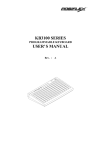
KB6600 Series
Programmable Keyboard
User’s Manual
Rev. Original
FCC Notes:
This equipment generates, uses, and can radiate radio frequency energy and, if not
installed and used in accordance with the instructions manual, may cause interference
to radio communications. It has been tested and found to comply with limits for a Class
A digital device pursuant to subpart J of Part 15 of FCC Rules, which are designed to
provide reasonable protection against interference when operated in a commercial
environment. Operation of this equipment in a residential area is like ly to cause
interference in which case the user at his own expense will be required to take whatever
measures to correct the interference.
Warranty Limits:
Warranty will terminate automatically when the machine is opened by any person other
than the author ized technicians. The user should consult his/her dealer for the problem
happened. Warranty voids if the user does not follow the instructions in application of
this merchandise. The manufacturer is by no means responsible for any damage or
hazard caused by improper application.
About This Manual:
This manual is written in an attempt with full strength to assist the user to utilize
the powerful programmable keyboard KB6600 series which consists of a 6 positioned
electronic control key and 84 press keys whic h provides excellent tactile click when
pressed, and an optional magnetic stripe reader for ISO standards. The KB6600 not
only is capable of being programmed to transmit whatever code a standard PC or PS2
keyboard can deliver, but also provides a great variety of programmability such that
contains all capabilities of the most modern programmable keyboards.
The manufacturer of this product heartily apologizes to the user for reserving the right
to change or to modify this manual without notice due to the rapid and constant
progress and improvement on science and technology.
The information in this manual contains only essential hardware concerns for general
user and is subject to change without notice. Posiflex reserves the right to alter product
designs, layouts or drivers without notification. The system integrator shall provide
applicative notices and arrangement for special options utilizing this product. The user
may find the most up to date information of the hardware from web sites:
http://www.posiflex.com or http://www.posiflex.com.tw
All rights are strictly reserved. No part of this documentation may be reproduced,
stored in a retrieval system, or transmitted in any form or by any means, electronic,
mechanical, photocopying, or otherwise, without prior express written consent from
Posiflex Inc. the publisher of this documentation.
© Copyright Posiflex Inc. 2004
All brand and product names and trademarks are the property of their
respective holders.
P/N: 19170900010
Part 1
I.
OVERVIEW
A. SCOPE
The KB6600 series is a series of powerful programmable keyboard
suitable for application in PC compatible system, programmable without TSR
under DOS, Win98/2000, Win XP embedded and Win XP Pro environment.
This series provides 84 keys (max.) of a comfortable size 19 x 19 mm in 6 x 15
matrix within which a 4 x 4 numerical keypad resides and a 6 position control
key which is capable of sending answer back codes according to the position
of the key.
B. FEATURES
1) Powerful programming ability (hot key programming,
programming under DOS, off-line programming under DOS,
programming under Windows, multiple page, multiple level,
whole range key content, time delay, position sense answer back
code, etc.)
2) True spill proof structure
3) Reliable and pleasant key click
4) Comfortable key size
5) Optional blank key, double key for alternative key group layout
6) Optional MSR (Magnetic Stripe Reader)
C. MODEL NUMBERS
MODEL #
DESCRIPTION
KB6600
Standard model (8 KB non-volatile memory)
KB6600M2
Keyboard with 2 tracks ISO7811 MSR (tracks 1 & 2)
KB6600M2/3 Keyboard with 2 tracks ISO7811 MSR (tracks 2 & 3)
KB6600M3
Keyboard with 3 tracks ISO7811 MSR (tracks 1, 2 & 3)
KB6600MJ
Keyboard with 2 tracks JIS II MSR (JIS I track 2 & JIS II)
II.
PACKAGE CONTENTS
1)
2)
3)
Programmable keyboard
Key clip x 1 (mounted at bottom of the programmable keyboard)
Accessory bag including:
Ø
Interface cable CCBLA-055-1 for PS2 KB port
x1
Ø
Legend sheet
x4
Ø
Control keys 4 pcs/set
x 1 (set)
Part 2
Ø
Ø
Ø
Posiflex product information CD
User’s manual
Key cap (for single key)
x1
x1
x 68
A. OPTION LIST
MSR (ISO track 1 & 2, ISO track 2 & 3, ISO track 1, 2 & 3, or
JIS I track 2 + JIS II) /pc
2) Double key with key cap / set
3) Blank key / pc
4) Single key top and key cap / set
1)
III.
INSTALLATION
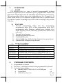
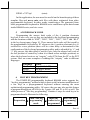
A. CABLE CONNECTION
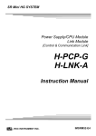
For installation in a PS2 or a compatible system with KB6600 connect
the 6 pin DIN male plug of cable CCBLA-055-1 out of the accessory bag to
the 6 pin DIN female connector at the left of the bottom of the programmable
keyboard. Connect the mini DIN 6 male plug of the cable to the PS2 or a
compatible system. Connect the PS2 keyboard or other PS2 keyboard wedged
device like a CCD scanner to the 6 pin mini DIN female connector at the
bottom of the programmable keyboard if required.
Monito r
PC
PC KB
CCBLA-055-1
KB6600
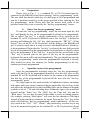
B. KEYTOP LAYOUT
The basic layout of this programmable keyboard is a matrix with 6 rows
and 15 columns to provide maximum 84 positions for push keys with a 6
position control key and LED indicators. Within these 84 positions there is
four by four matrix below the control key area configured as numerical keypad.
Part 3
This numerical keypad is a set of “numerical keys” which is composed of 12
numerical keys each is preprinted with one from the set of “0”, “00”, “.”, “1”,
“2”, “3”, “4”, “5”, “6”, “7”, “8” and “9” plus “-“, “+” and a double size
“Enter” key (ref. Fig. 3-6). However, there are means for the user to break the
monotony and to improve the efficiency in application of this programmable
keyboard.
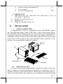
First of all, there are 4 legend sheets of different colors in the accessory
bag that the user may want to print the identification for each programmed key
into each cell of the sticker matrix and then stick each cell printed with the
identification onto the surface of the corresponding key top. A key cap from
the accessory bag can be snapped on the key top to protect the sticker (ref. Fig.
3-2). In this way the user may feel a lot easier in using the programmable
keyboard.
At the bottom of the programmable keyboard, the user may find an
adjustable key clip which can be used to pick up the key cap whenever
required (ref. Fig. 3-2). The two “feet” of the key clip should be pulled wide
for use with double key (ref. Fig. 3-3). It is advisable to use a flattop (minus
sign) screw driver to help getting the key top off when necessary (ref. Fig. 3-2
and 3-3 ).
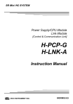
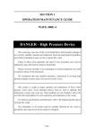
Whenever there comes the need to install a key top onto the
programmable keyboard, the user should notice that at the bottom of each key
top, one of the four walls is springy and in the hole on the keyboard to accept
the bottom of the key top there is a protuberance at the lower side. The user
should match the springy wall of key top against the protuberance in the hole
(ref. Fig. 3-4) and press the key top down till a click sound is heard. The key
cap (except the blank key) should be placed after the printed label is stuck onto
the key top.
Furthermore, there are blank keys available which the user can use to
form visible partitions or clusters of key tops on the programmable keyboard.
When the user wants to make a group of keys on the programmable keyboard
clearly separated from the rest part of the keyboard for certain specific
application, he/she can use the blank keys to replace the normal individual
keys around the area. The top surface of a blank key is at the ground level of
the key stroke for other keys (ref. Fig. 3-6). The blank key will not be pressed
down when pressed. The user may order for accessional quantity of the blank
keys as option for his/her application.
There are also double key available for the user to configure the
programmable keyboard such that the most frequently used keys may occupy
larger areas. The double key occupies two adjacent positions and uses only the
bottom position for key content (ref. Fig. 3-3). An example of using the above
mentioned alternate key tops is shown in Fig. 3-6
Part 4
protuberance
Fig. 3-2
Springy
wall
Fig. 3-3
Fig. 3-4
Single key
Fig. 3-5
Numerical keys
Double key
Fig. 3-6
IV.
APPLICATION
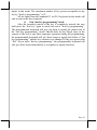
A.
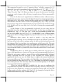
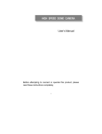
KEYBOARD CONSTRUCTION
Power-on LED
MSR indicator
6 position key
6 position key switch
15 x 6 push keys
Fig. 4-1
MSR slot
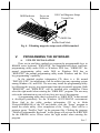
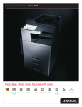
This keyboard is constructed of three parts on the top surface (ref. Fig.
4-1). A 6 position turning key switch area is at the upper right corner, a 15 x 6
matrix of push key switches occupies most of the top surface and a slot near
the right edge is designed for the Magnetic Stripe Reader of the -M2, -M2/3,
-M3, -MJ models.
In the rectangular area at upper right corner there are one 6 position
electronic key switch and two LED’s. The upper LED is for power-on
indicator and under power-on LED is the MSR indicator. The 6 position
Part 5
electronic key can be turned to one of the following 6 positions: LP, L0, L1, L2,
L3 and L4. It can only be taken out from the switch at positions L0 and L1.
The purpose of this electronic key serves 3 folds: When the key is switched to
(and extracted from) position L0, the whole keyboard output will be blocked
off by hardware to work as a security measure. A programmable answer back
code for the final position of the 6 position electronic key will be sent by the
keyboard to the host computer whenever the key is switched to a new position
for a programmable delay time or when the host computer sends a specific
code (E7h) to inquire the keyboard. The position of the electronic key
determines which page of the key content table for the 84 push keys applies,
while the definitions of the same key within different pages can be
programmed so absolutely independent to provide instant menu change over.
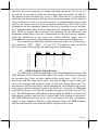
This turnable electronic key switch is delivered with a set of 4 pcs keys,
each marked as “PRG”, “REG”, “Z” and “GT”. The effective range of each of
the 4 keys can be illustrated by the following table and drawing.
LP
L0
L1
L2
L3
L4
PRG
REG
Z
GT
Y
Y
Y
Y
Y
N
N
Y
Y
Y
N
N
N
Y
Y
Y
Y
N
N
Y
Y
Y
Y
Y
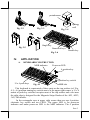
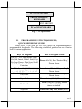
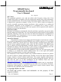
B. MSR (Magnetic Stripe Reader)
The MSR slot is near the right edge of the Programmable Keyboard. The
MSR indicator LED is located at the upper left corner of the block containing
the electronic key. There are three choices of the reader types – ISO 1,2 or 2,3
dual tracks and ISO triple tracks types. For card reading, be sure to insert the
card to the bottom with magnetic stripe of ISO card facing downward. The
movement of an ISO card can be either inserting the card from the top surface
at the upper end then sliding the card to the lower out of the slot, or sliding the
card from the lower of the slot till it reaches the upper end of the slot (ref. Fig.
4-2). The MSR indicator will light up in green when the MSR is ready to read,
blink during reading, and then give a green light if the reading is successful.
The MSR indicator will turn to be red if the reading fails due to improper
sliding or poor magnetic intensity of the magnetic stripe, the MSR indicator
will then turn back to green when the MSR is again ready to read.
Part 6
MSR Indicator
Power on
Indicator
ISO Card Magnetic Stripe
Toward User
MSR Slot
Reader Head Mark
Fig. 4 - 2 Reading magnetic stripe cards of ISO standard
V.
PROGRAMMING THE KEYBOARD
A. UTILITY INSTALLATION
There are in total three methods to program the programmable keys in
KB6600 series keyboard: “RWM.EXE” the straightforward direct read/write
programming utility under DOS or Windows DOS box; “KBM.EXE” the
normal programming utility under DOS or Windows DOS box or
“KBW.EXE” the normal programming utility under Windows and the “Hot
key programming” capability.
In the attached product information CD, there is a file named
“INSTALL.EXE” for installation of all the utilities into any operating system
among Windows 98, and DOS. The user may install the programming utility
by following the step by step instructions from this executable program. Both
“KBM.EXE” and “RWM.EXE” will be installed after completion. Please
select the right model when entering the “KBM.EXE” program. The user may
refer to the information on our web site for a preview of this program.
A programming utility that is referred to as “KBW.EXE” in this manual
is developed particularly for the Windows 98/NT/2000/XP environment.
Please find in the utility product information CD or in folder
\Drivers\KB\KB6600 of the CD and double click the “Setup” program to
install the whole utility. After completion of the “Setup”, there will be a
program group “Posiflex Tools” in the program files. Clicking the program
“Posiflex Programmable Keyboard” in this group will activate the KBW.EXE
for the KB6600 series. Please select the right model when entering the
program.
Part 7
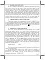
PC or PST SYSTEM
PROGRAMMABLE
KEYBOARD
EXT. KB PORT
PC or PS2 KEYBOARD
Fig. 5 - 1 Preparations
B. PROGRAMMING UTILITY (KBM.EXE)
1
QUICK REFERENCE GUIDE
Please refer to our web site for every detail in programming these
programmable keyboards. The following simplified guide severs as a concise
tool for instant application.
Keys To Program
How to Program Them
Esc, F1 - F12, Back Space, Shift,
Ctrl, Alt, Insert, Delete, End, Page
Up, Page Down, Print Scrn, Scroll
Lock, Break, and all Arrow
Functions
Press: (Alt-N), Esc, “Desired Key”,
Down Arrow
A - Z, 0 - 9, ~ ` ! @ # $ % ^ & * ( ) Press: Enter, “Desired Key or Keys”,
- _ = + } { [ ] | \ ’; ” : /. , < > ?
Down Arrow
Tab, Enter
Press: (Alt-N), “Desired Key”,
Down Arrow
Caps Lock
Press: Enter, (Alt-C), Down Arrow
Multishift
Press: (Alt-N), (Alt-M), Down
Arrow - - - - Press (Alt-M) as many
times as needed.
Seperator
In Between Any Text, Press (Alt-S)
Part 8
2
HARDWARE LIMITATION
In case of “multiple combination key” application which means pressing
three or more keys at the same time to obtain certain data output from the
keyboard, there could be some limitations inherent from the nature of
keyboard structure. The CPU of keyboard detects the contact between the
“horizontal” and “vertical” lines for each key press, recognizes which key is
pressed and sends correspondent data to the host computer. When there are
many keys pressed at the same time, and the pattern of the contacts coincides
with some special relationship, there are chances that the CPU of keyboard be
confused about exactly which keys are pressed. The user may change the
locations of the key-definition to prevent this once such confusion happens.
3
PROGRAMMING UTILITY (KBW.EXE)
This utility programs the programmable keyboard as KBM.EXE does
but using Windows application interface. Please use on - line help to program
the programmable keyboard. Use the connected PS/2 keyboard for data entry
of usual characters. Use mouse right click or the “
” key on keyboard for
data input of some special codes.
4
SHORTCUT UTILITY (RWM.EXE)
The feature of this RWM.EXE is designed mainly for the off-line
programming purpose and is very useful in quick reproduction of the
preprogrammed contents of the programmable keyboard. In such application,
the user should have either the preprogrammed keyboard or the
preprogrammed file with “.tpl” extension name which is the result of the
keyboard programming. The user may use RWM.EXE to directly transfer the
programmed result of the programmable keyboard to a “.tpl” file or directly
transfer a prestored “.tpl” file to a programmable keyboard without entering
the utility “KBM.EXE” or “KBW.EXE” which may take more keystrokes. For
instance, the user wants to transfer a file “XXX.tpl”, which was saved before,
to the programmable keyboard, he/she should type in following command in
subdirectory “POSIFLEX.D”:
RWM XXX.tpl
(enter)
This operation is quite recommended to be performed on a daily basis to
ensure the system stability.
On the other hand, when the user wants to save the contents of a
programmed keyboard, e.g. when he/she newly receives a programmable
keyboard, to a file named “YYY.tpl”, he/she should type in following
command in subdirectory “POSIFLEX.D”:
Part 9
RWM –r YYY.tpl
(enter)
In this application, the user must be careful on the housekeeping of these
template files and never mix such files with those originated from other
programmable keyboard. In other words, transferring a file generated from
other programmable keyboard to KB6600 series could mess up the data format
inside KB6600 series, and vice versa.
5
ANSWER BACK CODE
Programming the answer back codes of the 6 position electronic
key-lock is also very easy as they are included in the keyboard programming
with the locations coded as “KLP”, “KL0”, “KL1”, “KL2”, “KL3” and “KL4”
in the key-layout map of page L1. These answer back codes will be issued by
the programmable keyboard to PC whenever the 6 position electronic key is
switched to a new position (there will be a time delay as determined in the
configuration of the keyboard programming utility and is adjustable by “r” and
“t” key presses, this time delay is useful to give only the answer back code of
the last position of control key when it is turned across multiple positions) or
when the keyboard receives an “enquiry” code (E7h) from the PC or the PST
system. Here are some examples of sending this “enquiry” code in different
languages:
Language
C
BASIC
DEBUG
Syntax
outp (0x60, 0xE7)
out &H60, &H0E7
o 60 E7
6
HOT KEY PROGRAMMING
The POSIFLEX programmable keyboard KB6600 series supports the
“hot key programming” method which is most useful in instant modification of
a few keys in a preprogrammed keyboard without entering the more
sophisticated programming utility. Of course, the user may also use this feature
to program through out all 84 keys by 5 pages (LP and L1 to L4) at will. The
whole process of “Hot key programming” contains 4 steps for each key to be
programmed and is illustrated as following:
Preparation
Enter “hot key
programming”
mode
Input the
content to be
programmed
Exit “hot key
programming”
mode
Part 10
a.
Preparation
Please refer to Fig. 5 -1, a standard PC or PS-2 keyboard must be
connected to the KB6600 series before entering “hot key programming” mode.
The user shall then decide which key of which page is to be programmed and
turn the 6 position control key to the proper position before entering the “hot
key programming” mode. Please note that the answer back codes of the
position control key is not covered by the “hot key programming” feature.
b.
Enter “hot key programming” mode
To enter the “hot key programming” mode, the user must input the “hot
key” and identify the key on the programmable keyboard to be programmed.
The so called “hot key” is a special combination of keys pressed on the
standard PC or PS-2 keyboard. In KB6600 series, the “hot key” is defined as
pressing and holding the left “Alt” key while pressing the “PRT SC” (“Print
Screen”) key on the PC or PS-2 keyboard. And by doing so, the KB6600 will
give 2 beeps to notify that it is ready to receive the identification of which key
to be programmed. Right after the “hot key” is released, the user shall press the
key to be programmed on the programmable keyboard once to identify which
key to be programmed. If the “hot key” is pressed for the second time or the
“Esc” key is pressed prior to the press of the key on the programmable
keyboard, this mode will be aborted immediately. The user should not enter the
“hot key programming” mode when the programmable keyboard is already
fully loaded (no more free memory for further programming) by the key
contents previously programmed.
c.
Input the content to be programmed
Once the programmable keyboard enters the “hot key programming”
mode with the key to be programmed identified, what the user types on the
standard PC or PS-2 keyboard will be taken for the content to be programmed
into that key of the programmable keyboard till the user exits the “hot key
programming” mode.
The legal input in this mode includes all alphabetical letters (including
both upper and lower cases), numerical digits (applicable only for keys at the
area above the alphabetical keys and excluding those on the numerical keypad),
symbols (such as `!”#$ and excluding those arithmetic signs in the numerical
keypad) and the “Enter” key. The “Shift” key, the “Caps lock” key and the
“Back space” key are also accepted in this mode to serve an editing purpose
(for example, pressing “Back space” will erase the last character of the input
instead of being treated as a character for input). Pressing the “Esc” key in this
mode will abort the “hot key programming” mode immediately. All the rest
keys (such as the “Ctrl”, “Alt”, “Home”, any function key or arrow key or any
key in the numerical keypad) on the standard PC or PS-2 keyboard are illegal
Part 11
inputs in this mode. The maximum number of key presses acceptable to any
key by “hot key programming” is 32.
All the input from the standard PC or PS-2 keyboard in this mode will
also be sent to the host computer.
d.
Exit “hot key programming” mode
After the intended content of the key is completely entered, the user
shall press the “hot key” again to notify the end of “hot key programming”.
The programmable keyboard will give one beep to signify the normal exit of
the “hot key programming” mode. Should there be any illegal entry in the
content of the key or any other improper operation during the programming,
the programmable keyboard will give three beeps to signify the failure of “hot
key programming” and the key content is not changed. If the user pressed the
“Esc” key to abort “hot key programming”, the programmable keyboard will
also give three beeps immediately as a response to signify the abort.
Part 12
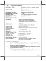
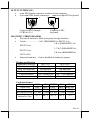
VI.
SPECIFICATIONS
CONSTRUCTION:
LED COLOR:
Spill-proof, 84 keys + 6 position control
key
Power on – Green
MSR – Green & Red
membrane plus rubber dome
3.2 mm
19 x 19 mm for normal keys (ivory)
“.”, “00”, “0” to “9”
19 x 19 mm transparent
KEY SWITCH TYPE:
KEY STROKE TRAVEL:
KEY TOP SIZE:
PREPRINTED KEYS:
KEY CAP:
PROGRAMMABILITY:
METHOD:
Software programming under DOS,
Win98, Win NT, Win 2000, Win XP
embedded or Win XP Pro without TSR
program
COVERAGE:
84 keys by 5 pages + one 6 -position
control key with answer back code
CODE TYPE:
ASCII or scan codes
LANGUAGE:
English or European, software configured
KEY-CONTENTS
LENGTH:
1 - 255 byte(s)/key
MEMORY:
Non-volatile memory, 8KB
INTERCHARACTOR
OUTPUT SPEED:
programmable 0 - 140 msec
TIME DELAY:
programmable 0 - 240 sec
MULTILEVEL:
8 levels max.
DOWN LOAD SPEED:
≤ 40 sec. For 8 KB
CONTROL KEY:
6 positions with programmable answer
back code for each position
POSITION CONTROL KEY:
l
6 positions (LP, L0, L1, L2, L3, L4), key extractable at L0 and L1
l
Hardware lock off all keyboard data output at L0 after transmitting
answer back code if programmed
l
Capable of giving programmable answer back code of each position
on position change of the key
l
Capable of giving programmable answer back code of each position
on receiving a specific code (E7h) from host computer
Part 13
OUTPUT INTERFACE:
l
6 pin DIN female connector: connect to host computer
l
6 pin mini DIN female connector: connect to input PS2 keyboard
Connects to PC through
CCBLA-055-1
Connects to PS2
keyboard
MAGNETIC STRIPE READER:
l
Decoder & interface Built in keyboard wedge interface
l
Tracks........................1 & 2 (KB6600M2 for ISO7811) or
2 & 3 (KB6600M2/3 for
ISO7811) or
1, 2 & 3 (KB6600M3 for
ISO7811) or
2 & rear (KB6600MJ for
JIS X 6302)
l
Start/end sentinels.....Can be disabled by hardware jumper
Reader specification
Applicable card type
ISO 7811
JIS X 6302
Card feed method
Manual
Manual
Card feed direction
Bi-direction
Uni-direction
Read / write function
Read only
Read only
Card feed speed
5 to 55 inches/sec. 100 ~ 1200 mm/sec.
Error rate
Less than 0.5%
Less than 0.1%
Card data format
Card standard
Track used
Recording method
Recording density
Recording capacity
characters / bits
IATA
Track 1
F2 M
210 BPI
79 / 7
ABA THRIFT JIS I
JIS II
Track 2 Track 3 Track 2 Rear side
F2 M
F2M
F2 M
F2 M
75 BPI 210 BPI 75 BPI 210 BPI
40 / 5
107 / 5
40 / 5
72 / 7
Part 14
POWER CONSUMPTION:
Voltage...................... 5VDC±10%
Current...................... 125 mA max. (Model KB6600)
150 mA max. (Models KB6600M2, KB6600M2/3,
KB6600M3, KB6600MJ)
MECHANICAL:
Dimension in mm.....… … 346 mm x 210 mm x 57 mm
Dimension in inches.… . 13.6” x 8.3” x 2.2” (W x D x H)
ENVIRONMENTAL:
Operating temperature......
Storage temperature..........
Relative humidity.............
Vibration..........................
Shock...............................
0°C to + 50°C
-20°C to + 70°C
90%, non-condensing
4G
40G
RELIABILITY INFORMATION:
Push key switch:........ 15,000,000 strokes min.
Memory:.................... 100 years min.
MSR head life: .......... 500,000 passes min.
APPLICABLE CONFORMITY:
CE, FCC CLASS A
Part 15