1
OUTDOOR SPEED BOME CAMERA
HIGH SPEED DOME CAMERA
User’s Manual
Before attempting to connect or operate this product, please
read these instructions completely
1
Contents
Important Safety Instructions………………………………………3
Caution…………………………………………………………………………4
Introduction……………………………………………………………………5
Drawing………………………………………………………………7
Mount…………………………………………………………………8
Connection……………………………………………………………9
Outdoor Installation …………………………………………………10
Indoor Installation……………………………………………………11
Main control board ……………………….…………………………12
ID code setting……………………………………………………... 13
Setting Protocol of zoom camera …..……………………………... 14
Protocol setting………………………………...…………………… 15
Setting Baud Rate…………………………………………………………….16
Operation…………………………………………………….……... 17
Camera OSD menu…..………………………………………………20
Operation of camera…………………………………….……………21
Protocol Code Funcation……………………………………….……22
General Failure Analysis Table………………………………………24
Before Installation……..……………………………………….……25
Specification…………………………………………………………26
2
Important Safety Instructions
1.
2.
3.
4.
5.
6.
7.
Read these instructions.
Keep these instructions.
Heed all warnings.
Follow all instructions.
Do not use this apparatus near water.
Clean only with dry cloth.
Do not block any ventilation openings. Install in accordance
with the manufacturer’s instructions.
8. Do not install near any heat sources such as radiators, heat
registers, or other apparatus (including amplifiers) that produce
heat.
9. Do not defeat the safety purpose of the polarized or grounding type
plug. A polarized plug has two blades with one wider than
the other. A grounding type plug has two blades and a third
grounding prong. The wide blade or the third prong are
provided for your safety. If the provided plug does not fit into
your outlet, consult an electrician for replacement of the
obsolete outlet.
10. Protect the power cord from being from being walked on or
pinched particularly at plugs, convenience receptacles, and the
point where they exit from the apparatus.
11. Only use attachments/accessories specified by the
manufacturer.
12. Use only with cart, stand, tripod, bracket, or table specified by
the manufacturer, or sold with the apparatus. When a used,
caution when moving the cart/apparatus combination to avoid
injury from tip-over.
13. Unplug this apparatus. When a cart is used, use caution when
moving the cart/apparatus combination to avoid injury from tip over.
14. Refer all servicing to qualified service personnel. Servicing is
required when the apparatus has been damaged in any way,
3
such as power-supply cord or plug is damaged, liquid has been
spilled or objects have fallen into the apparatus, the apparatus
has been exposed to rain or moisture, does not operate
normally, or been dropped.
CAUTION
To prevent damage which may result in fire or electric shock hazard,
do not expose this appliance to rain or moisture.
This device complies with part 15 of the FCC Rules. Operation is
subject to the following two conditions.
1) This device may not cause harmful interference, and
2) This device must accept any interference that may cause undesired
operation.
CAUTION:
Danger of explosion if battery is incorrectly replaced.
Replace only with the same or equivalent type recommended by the
manufacturer.
Dispose of used batteries according to the manufacturer’s instructions.
Introduction
Function Description
High Speed Dome Camera is an all-in-one high-tech monitoring
product, which integrates high-definition color video camera,
universal gear change pan-tilt and multi-function decoder, CPU
processor. This product furthest reduces the processes of connection
an installation between system reliability. Also the video camera is
very easy to install and maintain ,has many features ,such as
perfect shape, legerity and convenience ,simple operation and etc.
4
1. Integrate multi-function decoder
Built-in decoder consists of multi-protocol and communications
protocol. Communication serial baud rate is adjustable. Using the
simple finger-switch inside the Dome device, the products can be
compatible with kinds of systems and has very high commonality.。
2.Integrate full-view rotary station
Horizontal 360°unlimited continuous rotation and rotation rate can
be adjusted from 0.5 ~250 ° per second continuously. Vertical
rotation range is 0~90°and rotation rate can achieve0.5~130°/s.
3:Intelligent power-off memory operation
a. Design ideally ,Auto-flip to follow object。
b. Provides 128 preset points.
c.
Provide setting of scanning track and select scanning track
function.
d. Four groups of scanning tracks : Every group of scanning track can
set Max. 16 preset positions. If camera self support OSD menu
function. It can open completely when using .
e. Integrate multiple camera protocol. Support Max.5 different Brands
cameras.
f.
Integrate multiple protocol: Max. 20 kinds of communication
protocol. Transmission rate Selectable from 1200bps to 38400bps
g. Self-test can allow to store track that user edits arbitrarily and
information power-off memory .
h.
RS485 serial control, address of Dome device is from 1~511.
i.
Built-in 4 alarm input,2 output.
j.
k.
Outdoor speed dome camera have heater and radiator. They can
adjust temperature to delay dome camera ‘s life long.
Built-in surge and lightning strike protective equipment.
5
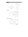
DRAWING
6
MOUNT
1.Ceiling Mount
2.Wall Mount
3.Embed In ceiling Mount
7
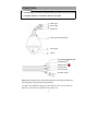
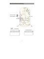
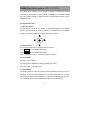
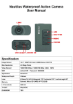
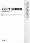
CONNECTIONS
Precautions
• The following connections should be made by qualified service personnel
or system installers in accordance with all local codes.
Power Input
Video Output
RS485 data
Aluminum Die Cast Housing
Acrylic dome
Camera
Green RS485+
RS485 data
Yellow RS485Yellow & Green
Blue AC Power
Brown AC Power
BNC Video output
Note: When powered up, the dome device performs a self-check (including one
panning, tilting, zooming and focusing operation).
If control wire of RS485 connects by the connective box, it can connect as
RS485A+ with blue wire, RS485B- with yellow wire.
8
Explanation of Alarm wire (Select)
This dome camera Built-in 4 alarm input(Red wire, Orange wire,
yellow wire, green wire ),Four wires share a black wire .2 output
(Pale wire, white wire). Two wires share a blue wire. Detail operation:
Please refer to the attached label on wire.
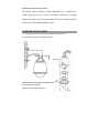
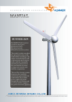
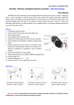
OUTDOOR INSTALLATION
1. Installing speed dome camera to the bracket using 4-M6 Screws.
2. Installing the bracket to an existing structure.
ID Code
THIS CAMERA IS SECURED FOR TRANSPORT
BY THIS RING AS SHOWN.
Please remove it before operating it.
9
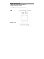
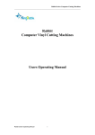
INDOOR INSTALLATION
1.Installing speed dome camera to the bracket.
2.Installing the bracket to the ceiling.
3. Installing the decorative wreath to the bracket.
Ceiling
Bracket
Decorative Wreath
10
Main Control Board (as following)
Protocol of zoom
Camera selector
11
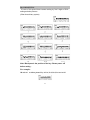
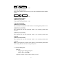
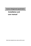
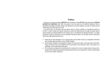
ID CODE SETTING
ID code of this speed dome camera setting by first 9 digits of SW1 ,
setting as below pictures.
(Other do as binary system)
Note: Black pane is the position of the key .Please power- off
before setting .
For example:
ID code:43 As follow picture Key of No.1,No.2,No.4,No.6 are in ON
12
NOTE: If the Control Wire parallel connection many speed dome camera the
farest dome camera ,you should connect JM1 which is in RS485 interface
of main control board .If the distance is very far ,you also should do as
above operation .Detail connect ,according to white line on the main
control board.
Connect JM1 which is in
RS485 interface of main
control board .
SETTING PROTOCOL OF ZOOM CAMERA
Note: The setting should be coincident the zoom camera
13
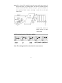
PROTOCOL SETTING
Protocol of this speed dome could transfer and freedom option by
first 5 digits of SW2, below is the detail of setting protocol :
14
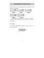
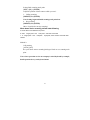
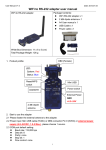
Setting Baud Rate of Dome Camera
Baud Rate setting of this speed dome camera by last 3 digits of SW2.
Setting as below pictures.
Common Baud Rate as below(bps):B01/9600;ALEC/4800;
VCL/4800 ; Pelco P/4800/9600 ; Pelco D/2400 ; A01/4800 ;
Santachi/9600。
For Example
Protcol :Pelco D, Baud Rate :2400bps,As follow picture Key of
No.3,No.6 are in ON
15
OPERATION(Default protocol
PELCO-D/2400)
The speed dome camera can be controlled remotely horizontal and vertical
movement. It is used with a system controller, separately. It is controlled remotely
from the controller through a serial connection to the RS-485 connector using a
twisted-pair cable.
Conventional Function
1. Pan / Tilt Function
The pan function will move the camera on all horizontal plane, to surveillance
position. The tilt function will move the camera on a vertical plane, to surveillance
position. The speed is variable according to the angle of joystick.
2. Zoom Function
2.1 The filming range can be set using the zoom function.
Press
TELE
the LCD displays Zoom Tele
Press
WIDE
the LCD displays Zoom Wide
Note: The bigger zoom is,the slower of joystick ‘s speed is .
2.2 Iris Function
Normally,Focus is AUTO。
Focus level can be adjusted by pressing [NEAR] and [FAR]
Move the joystick , focus will be auto .
3. Preset Memory
The preset memory function will memories camera positions and zoom, focus, etc.
Setting up to 128 preset camera positions can be memorized. Later, you can easily
recall any of the preset camera positions by entering its corresponding number, and
the camera will move the memorized position with all the preset settings.
16
3.1 To set a preset position
SET
+
N
+
ENTER
N: the number of preset position: 1~128
3.2 To call a preset position
When camera positions have been set, you can enter a memorized camera position
number.
Preset
+
N
+
ENTER
N: the number of preset position: 1~128
4. Delete a preset position
[PRESET]+[N]+[OFF]
N: the number of preset position: 1~128
5. To call cruise tracks:
[PRESET]+32+[ENTER]
This command can call the No.1cruise tracks. It can scanning preset points no.1~16.
[PRESET]+53+[ENTER]
This command can call the No.2cruise tracks. It can scanning preset points
no.17~31.
[PRESET]+49+[ENTER]
This command can call the No.3cruise tracks. It can scanning preset points
no.33~48.
[PRESET]+50+[ENTER]
This command can call the No.1cruise tracks. It can scanning preset points
no.65~80.
Note: If some points are not been set or delete, it will not scanning these points
when cruising. Resort 3 seconds in every preset points.
6.Setting scanning track
Method 1:
1. Setting begin scanning track point
[SET] + [51] + [ENTER]
Adjust the position of dome camera which you need .
17
Setting finish scanning track point:
[SET] + [52] + [ENTER]
Adjust the position of dome camera which you need .
3. Calling scanning:
[PRESET]+51+[ENTER]
Note: Setting begin and finish scanning track point first .
4. Stop scanning
[PRESET]+52+[ENTER]
(Move Joystick also can stop scanning)
When dome device scanning, default state following
a. Dome device scan between two points.
b. Scan “begin-point”and “end-point”and resort 3 seconds
c. If “begin-point”and “end-point” superpose, dome device horizontal 360°
rotation.
Method 2:
Call scanning
[AUTO]+[ON]
The speed dome camera scanning360 degree.Need not set scanning track
point .
Note: Above operation use for our company’s suited keyboard by example,
detail operation do as your keyboard menu
18
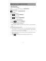
Camera OSD menu
Show Menu on display and setting other parameter of zoom
camera. Operation as follow:
Call No.57 preset position { [PRESET]+57+[ENTER]} to show the
main menu on display, and use [TELE]、[WIDE] to choose item, then
press [FAR]、[NEAR] to set and confirm .If you want to set other
items, you should come back main menu first. You can choose [EXIT]
item, then press [FAR]、[NEAR] to confirm .After these you will
come back main menu.
Note:After setting item parameter, must set No.57 preset position
{[SET]+57+[ENTER]} to set free the key of menu.If some camera
can’t be controlled by [FAR] and[NEAR].You can use [OPEN] to
come true operation
Note:Here in before operation use for our company’s suited keyboard by
example, detail operation do as keyboard menu
19
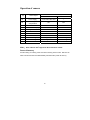
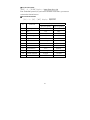
Operation of camera
(N)
Control object
The definition of key
PRESET+N+ENTER
SET+N+ENTER
Power supply
Backlight
compensation
Come back Initial value
/
ON
OFF
56
Min. illumination
ON
OFF
57
Menu/ Screen Display
ON
OFF
58
Digital Zoom
ON
OFF
59
Focus
AUTO
MANUAL
60
IRIS
AUTO
MANUAL
61
White Balance
AUTO
MANUAL
62
Static image
Image congeal
Normal image
63
Mirror image
Image mirror
Normal image
64
Color/black & white
Color
B/W
54
55
Note: Some cameras don’t support the above funcation of them.
Power-off memory
Provide setting of scanning track and select scanning track function. Self-test can
allow to store track that user edits arbitrarily and information power-off memory.
20
PROTOCOL CODE FUNCTION
1. B01 PROTOCOL
Ⅰ.To set up cruise tracks:
[SHOT] + N + [ON] The LCD displays
Input Tour No. N
N: The number of track
ON The LCD displays
Track = N1 Sum = N2
N1: track number
N2: sum of preset positions
Press TELE, the LCD displays No.N3 point
Press preset positions number
Press TELE the LCD displays No.N3 speed 3
Speed lever 1~8
1 stand fast speed
8 stand lowest speed
Then press TELE the LCD displays No.N3 time
Press first time of resorting in the cruise track
N3 the No. of current cruise track.
1. Setting 16 preset positions in this cruise track as above , repeat the steps as
above .
2. [TELE] Page up [WIDE] Page down,
3.
When setting the speed and time of No. n to 0 ,the preset position which are at
n-1 and before n-1 are all effective, but preset position No., speed and time
which are at n+1 and n change to 0 automatically .
4.
Option of speed from 1 to 8 are used for confirm the speed which move this
points to another point.
5.
Press OFF to save and exit. Move the joystick to exit without saving.
21
Ⅱ.To call cruise track
[SHOT] + N + [ENTER] Display:Input Tour No.: 01
Note: Under B01 protocol, If you want to call other cruise tracks, you must set
cruise tracks first and reserve.
Ⅲ. Accessional Function
[F1] + N + [ON] / [OFF] Display:Input No.
N.
Function
0
1
2
3
4
5
6
7
8
9
10
11
Camera power
BLC
Min. illumination
Menu/Display
Digital zoom
Reposition
FOCUS
IRIS
White Balance
Image
STATIC STATE
COLOR/BW
Explain
[F1]+N+[ON]
[F1]+N+[OFF]
ON
OFF
ON
OFF
ON
OFF
ON
OFF
ON
OFF
Enantiomorphous
Auto
Manual
Auto
Manual
Auto
Manual
Enantiomorphous
Normal
Congeal
Normal
Color
BW
22
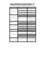
General Failure Analysis Table
Problem Description
After power on, no
motion and no image
Self test is
exceptional, there
is image but with
motor noise “wu”
Self-test is normal,
but have no image
Self-check ok but
cannot control
Vague image
Dome device is not
controllable.
Iris of the Dome device
is not
controllable.
Possible Reason
Power supply module is
damaged or power is not
enough.
Power cable is connected
improperly
Failure occurs on
engineering line.
Troubleshooting
Change
Correct
Eliminate
Mechanical failure
Examine and Repair
Video camera is slantwise
Put right
Change power that meets
requirements. It is
recommended to place
the power switch near
the Dome device.
Power supply not enough
Video line is connected
mistakenly.
Video line is poor contact.
Video camera is damaged.
Control signal line is
connected mistakenly.
Position of Dome device does
not match.
Protocol setting is wrong
Reset and on power again
Video line is poor contact.
Eliminate
Power supply not enough
Too much load or
communication distance
is too long.
Correct
Eliminate
Change
Correct
Reselect
Change
Confirm terminal
resistance Add code
distributor
Self-test is exceptional
On power again
Bad connection of control
Operation of Host has
problem.
Press to full connect
Iris is in manual status.
23
On power again
Use control command to
set iris to manual
status and iris can
be controlled.
Before Installation
Checking the contents of the package. Be sure to check if the following items
are included in the package.
1. PZT dome camera
2. Camera Holder (Mount)
3. User’s manual
4. Setscrew
What should be done during installation and use
1.
2.
Do not disassemble the camera on your own.
Be careful when handling the camera at all times. Do not strike the
camera with your fists or shake it. The camera should be stored and
treated with care to avoid any damage.
3. Do not put or operate the camera in rain or wet places.
4. Do not scrub the camera body with rough sandpaper when it is stained.
Please use a dry cloth at all times.
5. Put the camera in a cool area free from direct light. Otherwise, the
camera may be damaged.
24
SPECIFICATION
Panning range
360°endless
Pan speed
0.5~250°/sec
Tilt range
90°(180°Reversal auto-flip )
Tilt speed
0.5~130°/sec
Communication
RS485
Preset position
128
Track
4 cruising tracks and 2scanning track
Baud Rate
1200/2400/4800/9600/19200bps
Power
AC24V/DC12V
45W(Outdoor)/ 15W(Indoor)
Operating
temperature
Indoor 0 ~40
Outdoor -30 ~55
≥48dB
S/N Ratio
1.0Vp-p/75Ω
Video output
25