1
Navigation Guide
by genoQs Machines, Stuttgart, Germany ©2009
www.genoqs.net
v1.62
WARNING
To prevent fire or shock hazard,
do not expose the device to
rain or moisture.
Important Notice
The material in this document is copyright to genoQs Machines, and may not be
quoted or reproduced in any form without written permission from the company.
LIMITED SOFTWARE WARRANTY POLICY
All the software provided with, or purchased especially for, genoQs Machines products has
been tested for functionality. genoQs Machines will make its best efforts to correct
reported software defects for future releases subject to technical feasibility.
genoQs Machines makes no warranty or representation either expressed or
implied with respect to the system's performance or fitness for a particular purpose.
In no event will genoQs Machines be liable for direct or indirect damages arising
from any defect in the software or its documentation. Further, genoQs Machines
will not accept any liability for any programs, sounds, audio recording or sequences stored in
or used with genoQs Machines products, including the cost of recovery of such data.
The warranties, remedies and disclaimers above are exclusive and take precedence over all
others, oral or written, express or implied, to the extent permitted by law in the geographical
area of the product's use. No employee of genoQs Machines, agent, distributor or
employee of an agent or distributor is authorized to offer any variation from this policy.
Limited warranty
genoQs Machines units are sold with tree year full warranty.This warranty covers all malfunctions that may occur from
normal use. Damage caused by careless handling (improper voltage connected, exposure to damp, abuse etc.) is not
covered. The unit can only be returned for repair after agreement from genoQs Machines. Customer covers cost of shipping of
malfunctioning unit from customer to genoQs Machines. genoQs Machines covers shipping from genoQs Machines back to customer.
genoQs Machines agrees to offer spare parts and service for all units produced by genoQs Machines also after the warranty expires as
long as is possible. The warranty applies to the physical unit and applies also for customers buying units second hand where the warranty still is valid. The warranty is void without a readable serial number label.
FCC compliance statement
This device complies with part 15 of the FCC rules. Operation is subject to the following two conditions: (1) This device
may not cause harmful interference, and (2) this device must accept any interference received,
including interference that may cause undesired operation.
NOTE: This equipment has been tested and found to comply with the limits for a Class B digital device, pursuant to
Part 15 of the FCC Rules. These limits are designed to provide reasonable protection against harmful interference in
a residential installation. This equipment generates, uses and can radiate radio frequency energy and, if not installed
and used in accordance with the instructions, may cause harmful interference to radio communications. However,
there is no guarantee that interference will not occur in a particular installation. If this equipment does cause harmful
interference to radio or television reception, which can be determined by turning the equipment off and on, the user
is encouraged to try to correct the interference by one or more of the following measures:
• Reorient or relocate the receiving antenna.
• Increase the separation between the equipment and receiver.
• Connect the equipment into an outlet on a circuit different from that to which the receiver is connected.
• Consult the dealer or an experienced radio/TV technician for help.
European Union regulation compliance statement
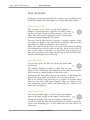
This symbol indicates that your product must be disposed of properly according to local laws and regulations.
The lightning flash with arrowhead symbol, within an equilateral triangle, is
intended to alert the user to the presence of uninsulated “dangerous voltage”
within the product’s enclosure; that may be of sufficient magnitude to
constitute a risk of electric shock to persons.
WARNING: WHEN USING ELECTRIC PRODUCTS, BASIC PRECAUTIONS SHOULD ALWAYS
BE FOLLOWED, INCLUDING THE FOLLOWING:
WARNING
Octopus is designed to be used in a standard household environment. Power requirements for
electrical equipment vary from area to area. Please ensure that your Octopus meets the power requirements in your area. If in doubt, consult a qualified electrician or genoQs Machines.
120 VAC @ 60 Hz for USA and Canada
220~240 VAC @ 50 Hz for Europe
240 VAC @ 50 Hz for Australia
IMPORTANT SAFETY INSTRUCTIONS
1.
2.
3.
4.
5.
6.
7.
8.
Read these instructions.
Keep these instructions.
Heed all warnings.
Follow all instructions.
Do not use this apparatus near water.
Clean only with dry cloth.
Install in accordance with the manufacture's instructions.
Do not install near any heat sources such as radiators, heat register, stoves, or other apparatus
(including amplifiers) that produce heat.
9. Do not defeat the safety purpose of the polarized or grounding-type plug. A polarized plug has
two blades with one wider than the other. A grounding type plug has two blades and a third
grounding prong. The wide blade or the third prong are provided for your safety. If the provided
plug does not fit into your outlet, consult an electrician for replacement of the obsolete outlet.
10. Protect the power cord from being walked on or pinched particularly at plugs, convenience
receptacles, and the point where they exit from the apparatus.
11. Only use attachments/accessories specified by the manufacturer.
12. Use only with the cart, stand, tripod, bracket, or table specified by the manufacturer, or sold
with the apparatus. When a cart is used, use caution when moving the cart/apparatus combination to avoid injury from tip-over.
13. Unplug this apparatus during lightning storms or when unused for long periods of time.
14. Refer all servicing to qualified service personnel. Servicing is required when the apparatus has
been damaged in any way, such as power-supply cord or plug is damaged, liquid has been
spilled or objects have fallen into the apparatus, the apparatus has been exposed to rain or
moisture, does not operate normally, or has been dropped.
15. Do not expose this apparatus to dripping or splashing and ensure that no objects filled with
liquids, such as vases, are placed on the apparatus.
WARNING
THIS APPARATUS MUST BE EARTHED
IMPORTANT
Ensure that all the terminals are securely tightened and no loose strands of wire exist.
Before replacing the plug cover, make certain the cord grip is clamped over the outer sheath of the
lead and not simply over the wires.
AVIS POUR LES ACHETEURS CANADIENS DU OCTOPUS
Le présent appareil numérique nʼément pas de bruits radioélectriques dépassant les limites
applicables aux appareils numériques de la Class B prescrites dans le Règlement sur le
brouillage radioélectrique édicté par le ministère des Communications du Canada.
This digital apparatus does not exceed the Class B limits for radio noise emissions from digital
apparatus set out in the Radio Interference Regulations of the Canadian Department of Communications.
VENTILATION
Do not prevent the unitʼs ventilation, especially by placing the unit on soft carpet, in a narrow
space, or by placing objects on the unitʼs chassis—top, side, or rear panels. Always keep the
unitʼs chassis at least 10 centimeters from any other objects.
CHANGES OR MODIFICATIONS NOT EXPRESSLY APPROVED BY THE MANUFACTURER
FOR COMPLIANCE COULD VOID THE USERʼS AUTHORITY TO OPERATE THE EQUIPMENT.
COPYRIGHT NOTICE
genoQs Machines Octopus is a computer-based device, and as such contains and uses software in ROMs.
This software, and all related documentation, including this Operatorʼs Manual, contain proprietary information which is protected by copyright laws. All rights are reserved.
The software and its documentation is open source, and therefore may be copied, adapted, transferred or
modified to the extent permitted by the GPL - GNU Public License.
octopus - MIDI Control Sequencer
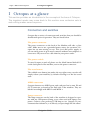
Introduction
Welcome, and sincere congratulations to the purchase of your new sequencer, a
genuine genoQs Machines Octopus!
You now own one of the definitely finest MIDI instruments ever built. We
proudly put in your hands a device built to drive your creativity and provide you
joy for years to come.
Octopus is conceived as a living instrument with long-lasting value, to help you
search and discover new sonic territory, rewarding you with an unequalled haptics
experience.
We invite you to explore the capabilities of Octopus as you like and provide this
manual as a start-up guide. Herein, you will recognize many known terms and
concepts. However, others may be used slightly differently from what you would
expect and some may be entirely puzzling.
This is why we recommend that once you are over the first wave of pushing buttons, flashing lights and turning knobs you read this guide end-to-end carefully –
and we are aware that no-one likes to read the manual..
Taking a step back, we do appreciate the complexity that Octopus is able to provide. Don’t get intimidated! You will soon discover fast ways of operation to best
suit your style and preference, the comfort zone where you are most productive.
But remember that only few clicks away await things that you had never thought
of doing or achieving. This is what Octopus is about – at every stage and no matter what - you are encouraged to experiment, explore and push the boundaries!
Gabriel Seher and Marcel Achim
Stuttgart, Germany 2009
Please check our web site regularly for latest news, software and documentation
http://www.genoqs.net
Navigation Guide
octopus - MIDI Control Sequencer
Navigation Guide
octopus - MIDI Control Sequencer
Table of contents
I Octopus at a glance
1
Connectors and switches........................................................................................... 1
The Octopus world...................................................................................................... 3
Navigation basics........................................................................................................ 4
Grid.................................................................................................................................. 5
Pages................................................................................................................................ 6
Tracks.............................................................................................................................. 7
Steps................................................................................................................................ 7
Mutators......................................................................................................................... 7
Attributes....................................................................................................................... 7
Attribute Maps............................................................................................................. 8
MIDI Control (CC) Maps.........................................................................................8
The front panel............................................................................................................ 9
II First steps
11
Connect and power-on.............................................................................................. 11
General controls......................................................................................................... 13
Interface conventions............................................................................................... 15
Step - basic operations.............................................................................................16
Basic track operations.............................................................................................. 18
Track chaining............................................................................................................. 21
Step real-time entr y.................................................................................................. 23
The MODE block...................................................................................................... 24
III Step mode
25
Basic operation........................................................................................................... 25
Step attributes............................................................................................................ 26
Step mutators............................................................................................................. 29
Step selections.............................................................................................................31
Navigation Guide
octopus - MIDI Control Sequencer
IV Track mode
33
Basic operation............................................................................................................33
Track attributes.......................................................................................................... 34
Track mutators............................................................................................................ 38
Track selections.......................................................................................................... 41
Track chaining............................................................................................................ 42
Track program changes............................................................................................ 44
Track tempo multipliers.......................................................................................... 46
Track auxiliaries......................................................................................................... 48
V Page mode
51
Basic operation............................................................................................................51
The Mixer block......................................................................................................... 52
Working with Mix maps........................................................................................... 53
Mix map targets......................................................................................................... 54
EDIT state................................................................................................................... 56
EDIT PERFORM state............................................................................................ 57
Editor MCC state...................................................................................................... 59
Page mutator functions........................................................................................... 60
Bank view..................................................................................................................... 61
Play mode.....................................................................................................................62
VI Grid mode
65
Basic operation........................................................................................................... 65
Page operations......................................................................................................... 66
Page clusters................................................................................................................68
Page play parameters............................................................................................... 69
Page follow................................................................................................................... 71
VII Performance tools
73
Working with pages................................................................................................... 73
Working with step selections................................................................................. 77
MIDI Control Maps................................................................................................. 78
Navigation Guide
octopus - MIDI Control Sequencer
Page sets....................................................................................................................... 79
Grid-Track mode........................................................................................................80
VIII Musical tools
83
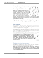
Step chords.................................................................................................................. 83
Chord ground rules
83
Playing chords
83
Step polyphony
84
Random note picks from chord pool
84
Step phrases.................................................................................................................86
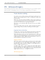
IX Advanced topics
91
Track direction editing............................................................................................ 91
A general view on directions
91
Playing direction maps
92
Track attribute maps................................................................................................. 95
Working with attribute maps
96
Map factors
98
Step events................................................................................................................ 100
The Effector.............................................................................................................. 102
The EFF mechanism
103
Playing the Effector
104
Editing step phrases............................................................................................... 106
Hypersteps.................................................................................................................109
Note attribute computation................................................................................. 110
X MIDI IN
113
Note stream recording............................................................................................ 113
Step note recording..................................................................................................117
Advanced recording................................................................................................. 119
MIDI Control Map learning................................................................................. 121
External force-to-scale........................................................................................... 122
External scale editing.............................................................................................. 123
External program change....................................................................................... 124
XI General tools
127
Navigation Guide
octopus - MIDI Control Sequencer
Utility functions....................................................................................................... 127
MIDI clock synchronization................................................................................ 128
System load handling.............................................................................................. 130
Saving the instrument state.................................................................................. 132
Exporting memor y content to MIDI.................................................................134
Contact
137
Navigation Guide
octopus - MIDI Control Sequencer
I Octopus at a glance
I Octopus at a glance
This section provides an introduction to the concepts at the base of Octopus.
The impatient reader may come back to this section once confusion sets in
and nothing makes sense anymore.
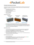
Connectors and switches
Octopus has a variety of connectors and switches that you should be
familiar with prior to operation. They are listed below.
The power connector
The power connector on the back of the Machine will take a 3-line
cable. Make sure to use a grounded power source for operation. Octopus has an auto-sensing 110-240 Volt (50-60Hz) power supply so
you can safely power it up in most countries without extra adapters or
converters. All you need is a cable that fits your power outlet.
The power switch
To turn Octopus on and off, please use the black button labeled I/O
on the back panel of the machine, next to the power connector.
The reset button
The reddish reset button just under the top right rotary encoder will
simply reboot your machine, by default resetting it to the last saved
state.
MIDI connectors
Octopus features two MIDI ports, and each port has its own IN and
OUT connector, as found on the back side of the machine. They are
labeled accordingly with MIDI 1 and MIDI 2.
Lamp connector
The lamp connector on the back of the machine is designed to operate with any USB-powered lamp, as are often used with laptop computers. Connect your preferred USB lamp to use Octopus in environments that demand it, or if (like us) you just simply like the effect!
1
Navigation Guide
octopus - MIDI Control Sequencer
I Octopus at a glance
USB connector
The USB connector on the back of Octopus does currently not carry
and function related to musical applications and should be seen as
something you should be only concerned with if you are interested in
development or change of the Octopus software.
Navigation Guide
2
octopus - MIDI Control Sequencer
I Octopus at a glance
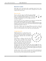
The Octopus world
In brief, the Octopus world consists of
• entities or objects
• attributes that are associated with them, and
• functions that modify those objects or their attributes.
This model allows for modifications of the objects in the most flexible manner and all in real time, with the sequencer running!
It is all done using an admittedly intimidating, but reportedly highly
intuitive and accessible user interface.
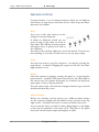
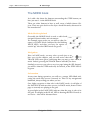
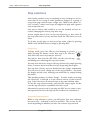
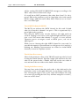
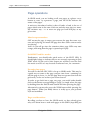
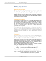
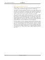
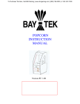
The Octopus object model
The master Octopus object is the GRID, which contains PAGES,
each of them containing TRACKS, which are made up of STEPS.
Each object is associated with attributes and functions that can be
operated upon. The diagram depicts at a high level the Octopus hierarchy of objects and their related attributes.
3
Navigation Guide
octopus - MIDI Control Sequencer
I Octopus at a glance
Navigation basics
The Grid contains all Page objects and each Page is made up of
Tracks and Steps. Moving around this hierarchy tree is trivial: to jump
between leaves you can always go up a level and down again.
Additionally, in most situations direct paths are also provided, allowing you to jump directly from one leaf to another.
Just as an example, assuming you are in the GRID mode, you would
hold the PAGE button and select the page you would like to jump
into, by pressing its button. Or you would double-click on the corresponding page button.
You would do the same to get further down into a specific track and
from there into a specific step. You may also choose to go from a page
into a step directly, as we will see later.
Navigating back up the tree is only one click away, and will take you
directly to the selected level. Or simply use the ESC key to always get
to the PAGE level of your current page, arriving at a known starting
point.
Similarly, in Track mode, press TRACK and the selector corresponding to the track you would like to jump to. This works in MAP mode
as well. In Step mode, press and hold STEP and press a grid button to
jump to the step corresponding to the pressed button.
Navigation Guide
4
octopus - MIDI Control Sequencer
I Octopus at a glance
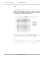
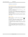
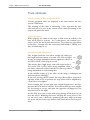
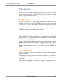
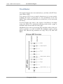
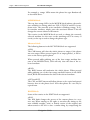
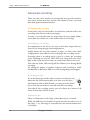
Grid
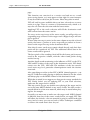
Octopus provides a total of 144 pages grouped in 9 banks of 16 pages
each, making up the GRID.
Visually a bank corresponds to one row of the matrix; hence a page
corresponds to one button of the matrix. This accounts for 9 rows
(row 1-9), with row 0 serving as a grid set selector.
Each bank can be activated for current play by selecting one of its
(non-empty) pages. This means that up to 9 pages may be played concurrently. For an overview please take a look at the diagram.
MIDI data output
Depending on the number of concurrently active tracks and the density of the produced MIDI data, it is possible to overload the MIDI
stream. A more complete discussion of various system and MIDI
loading is found in the section on System Load Handling.
5
Navigation Guide
octopus - MIDI Control Sequencer
I Octopus at a glance
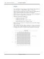
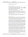
Pages
One can think of Octopus' pages as track containers. The number of
tracks in a page is 10, with a default length of 16 steps each.
Musical structures longer than 16 steps are built by chaining tracks in
a page, such that chained tracks are played consecutively.
Musical structures shorter than 16 steps can be built by using skipped
steps in tracks, for example. More on this later.
The preset chain modes available are:
• 10 tracks of 1 row each (default)
• 5 tracks of 2 rows each
• 2 tracks of 4 rows each + a track of 2 rows
• 1 track made up of 8 rows + a track of 2 rows.
However, the user is also free to build any other track chain configuration, as desired.
This, combined with the ability to play up to 9 pages concurrently
and each of the 9 pages being part of a cluster of at most 16 consecutive pages gives you a lot of room for both composition and live play.
Navigation Guide
6
octopus - MIDI Control Sequencer
I Octopus at a glance
Tracks
If pages are Octopus' track containers, then tracks are the step containers. Apart from other attributes, each track has a locator associated with it which can be controlled independently from locators of
other tracks.
Steps
In Octopus steps are the smallest meaningful entities, for example
notes in a musical context. In track mode the individual steps of a selected track can be modified across their available range of attributes.
Mutators
Entities or attributes of entities can be operated upon using mutators
(or functions), for example clear, randomize, modify, copy, paste, and
others.
While the modify function is mapped directly to the knobs as described in the operation mode section, the others are invoked by
pressing the appropriate mutator buttons.
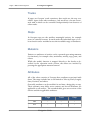
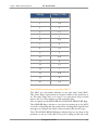
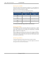
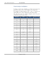
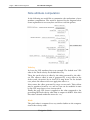
Attributes
All of the above entities of Octopus have attributes associated with
them. The range includes but is not limited to Velocity, Pitch, Length,
Start, Position, and others.
Generally, attributes can be modified in real time, during play or stop.
Their semantics may differ across entities and not all attributes are
applicable to all entities. The attached table gives an overview of the
entities and their applicable attributes.
7
Page
Track
Step
VEL
+
+
+
PIT
+
+
+
Navigation Guide
octopus - MIDI Control Sequencer
I Octopus at a glance
Page
Track
Step
LEN
+
+
+
STA
+
+
+
POS
+
+
+
DIR
+
AMT
+
+
GRV
+
+
MCC
+
+
MCH
+
Attribute Maps
The attribute maps are basically views associated with Track objects
which will allow you to view and edit directly the values of all steps in
a track, for a specific attribute.
For example, the velocity map of a track will show you at a glance all
step velocities, allowing you to change them directly by the press of a
button.
MIDI Control (CC) Maps
The MIDI Control Maps are simply assignments of CC functionality
to the Mixer knobs of Octopus.
You may use Controller Maps to freely assign MIDI Controllers and
their appropriate channels to the Mixer knobs, independently of
what is going on in the current page.
Navigation Guide
8
octopus - MIDI Control Sequencer
I Octopus at a glance
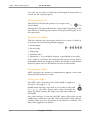
The front panel
The Octopus front panel consists of visual groups which we will name
here and to which we will refer in the course of this document. They
are explained in a left to right order.
MIX encoders
Each row has a dedicated left rotary encoder – in the MIX (Mixer)
group.
SEL buttons
Each row has a dedicated button in the SEL (Selector)
group.
MATRIX
The MATRIX refers to the field of 16x10 buttons.
The buttons take on various functions, depending on the operating
mode of the sequencer. The most obvious one is probably, when matrix rows represent tracks of 16 steps each.
Right below the matrix is the MIX TARGET field which determines
the functionality of the MIX rotary knobs.
MUT buttons
Each row has a dedicated button in the MUT (Mutator)
group.
EDIT encoders
Each row has a dedicated left rotary encoder – in the EDIT (Editor)
group.
Circle
The circle is made of buttons that provide a range of functionality
that applies across modes and objects.
Among other controls, the circle includes the SCALE, MODE,
TRANSPORT, and CHORD fields and the MAIN knob.
Each of the listed building blocks of the front panel takes on specific
functions according to the active mode at any point in time.
9
Navigation Guide
octopus - MIDI Control Sequencer
I Octopus at a glance
Navigation Guide
10
octopus - MIDI Control Sequencer
II First steps
II First steps
This section is intended to get you up and running with your first sequence,
and teach you the basics of Octopus operation in the process. You are encouraged to use the learned material and experiment further.
Connect and power-on
Connecting MIDI and a sound source
Start simply by connecting just one sound source to the MIDI OUT 1
port and then use the provided power cord to connect Octopus to a
power outlet.
Set your sound source to receive on channel 1 and also choose a
pitched sound with a medium release time. Something like piano may
be suitable, but don’t feel constrained in any way.
Power-on
Power on the unit by flipping the power switch.
If you have connected a USB lamp in the port labeled “Lamp”, you
should see it turn on immediately, and about two seconds later you
should see some of the front panel LEDs turn on.
The LED labeled PAGE should be blinking orange. Congratulations –
you are now ready to engage on a long and rewarding journey with
your Octopus sequencer!
Upon power-on (or reset), Octopus starts in the state that was last
saved to its internal FLASH (non-volatile) memory.
When you power up the machine for the first time, or after a memory
refresh, the machine is starting up with its “factory default” values.
Bypassing memory reload
By the same token, if you hold the CLR button down while powering
up the machine, Octopus will not load the FLASH memory contents,
but will simply start with the factory defaults.
Start-up defaults
The defaults include having the master tempo at 120 b.p.m., all tracks
running on direction 1, all tracks set to send on MIDI channel 1 of
11
Navigation Guide
octopus - MIDI Control Sequencer
II First steps
port 1, and a particular pitch assignment for tracks 0-9 as follows: C3,
D3, E3, G3, A3, C5, D5, E5, G5, and A5. Octopus may be reset to this
default condition at any time during operation.
Resetting to start-up defaults
Please note that doing this will erase any changes you have made and
possibly want to keep, so use this with extreme caution!
Press and hold the GRID mode button, while pressing the CLR button. Again, this only clears the RAM (volatile) memory contents and
leaves the content of the FLASH (non-volatile) memory untouched.
Navigation Guide
12
octopus - MIDI Control Sequencer
II First steps
General controls
Octopus features a set of transport buttons, which are no different
from what you may know from other devices. Start, Stop and Pause
functions are available.
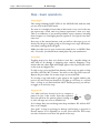
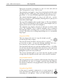
Play
Press any of the play buttons in the
transport section as depicted.
It makes no difference which one you
press as long as they show an arrow in
their label. The difference between them
will appear later, so please bear with us
for a moment.
You will see the red chase light move across the matrix. If you do not
hear anything, it is because you have not yet set any steps to play.
Stop
You may now want to stop the sequencer – do that by pressing the
stop button – as labeled. Stopping the sequencer will reset the chase
light position to zero.
Pause
Once the sequencer is playing, you may also pause it – by pressing the
pause button – as labeled. The pause button freezes the chase light at
the current step. To continue from pause (to continue) you may press
pause again, or any of the play buttons.
You may want to play a bit with the transport buttons to get yourself
familiar with how they work.
Master Tempo
Before you continue, you may want to set a different master tempo
for the sequencer. Simply turn the MAIN rotary encoder in the top
right corner – clockwise (increase) or counter-clockwise (decrease).
As you turn the knob, you will see funny things happen to the lights
of the top left quadrant of the outer circle. This part of the panel
shows the current master tempo and displays its value.
13
Navigation Guide
octopus - MIDI Control Sequencer
II First steps
Two other things to notice here: the LED of the button labeled
Tempo is orange – this indicates that the encoder is regulating the
tempo.
Navigation Guide
14
octopus - MIDI Control Sequencer
II First steps
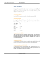
Interface conventions
Number display convention
The red dots have to be understood as multiple of tens, the green dot
represents the value of ones in the number on display. Plus there is
another red light potentially lighting up, labeled 100. That adds 100
to the number.
For example, 143 would be represented by the LEDs 100, 1, 2 and 4
lighting red, and 3 lighting green.
One exception to the rule is numbers where the tens and the one are
the same digit - in that case the digit in question will light orange. For
example 77 will be displayed as 7 LEDs with LED 1-6 lighting red and
LED 7 lighting orange.
Experiment a bit with this and you will get a good feel for this representation quickly. You will re-encounter it at many other occasions as
we move along.
Click convention
While we are here, we can introduce another convention:
the click convention.
You can directly select a value by pressing the buttons in
the tempo area. Double click on a number to set the ten’s
(red) value and single click to set the one’s (green) value.
For example double click on 7 and single click on 2 to set a tempo of
72. Note that by just double clicking on a number, the ones value is
set to zero.
This makes it very quick and easy to select round values like 60, 80,
or 120. Selecting non-round values is just one more click away.
As with the number display convention, the click convention is used
all across the instrument’s interface, so we will run into it over and
over again.
15
Navigation Guide
octopus - MIDI Control Sequencer
II First steps
Step - basic operations
Step toggle
The orange blinking PAGE LED in the MODE field indicates that
you are now in the PAGE mode.
For now it is enough to know that in this mode every row in the matrix represents a track, and every button represents a note or a step.
This is no different as you would probably expect anyways, knowing
that Octopus is a chase-light pattern sequencer. Let’s press some buttons now.
Press any of the matrix buttons, and you will see the steps go on, indicated by the green lights going on. Pressing active steps will deactivate them, turning them off again.
Make sure that you set your connected sound device to MIDI Channel 1. If you do, you should hear sound played by your synthesizer.
Step skip
Toggling steps as we have seen before is sure fine – another thing you
may want to do though, is skipping steps entirely. Skipping a step
means that the chase-light will simply ignore the step and just move
to the next un-skipped one.
To skip a step, press and hold the button of the step you want to skip
and then click the MUT button. You will see the step LED turn red.
Repeat the procedure for as many steps as you would like.
To un-skip a step and make it play again in the regular fashion, just
press it by itself and you should see its light go off. Press it a second
time - as long as you don’t hold the MUT button pressed, you will see
it toggle on as an active step.
Step tweak
Use what you have learned so far to compose a
pattern in one of the tracks. Start the sequencer
and you will hear the pattern played, boring as it
is, since all steps are set to a default level.
Let’s change that, but tweaking some Step attributes. We will use PIT
here as an example.
Just “grab” a Step by pressing its button and keeping it pressed (it
doesn’t matter if it’s originally on or off). Now turn the PIT rotary
encoder clockwise to increase the pitch of the step.
Navigation Guide
16
octopus - MIDI Control Sequencer
II First steps
Turning PIT counter-clockwise will decrease the pitch – one halftone per encoder click. The PIT rotary is the second one from the
top of the EDIT block.
You will now hear that the pitch of the step has changed every time
the chase-light passes it.
Feel free to experiment as you wish, with other attributes and refer to
the section on STEP mode for details.
Grab other steps and play around until you shape your pattern into
something you like before moving on.
Ghost toggle
Press and hold pressed two or more step buttons placed in separate
rows but in the same column. Let’s use for instance the rows 3 and 4.
Press a step in row 3 and at the same time a step in row 4 – and make
sure you do not release the buttons yet.
Now toggle steps in row 3 – and you will see that the steps in the
same column of row 4 will be toggled as well. Or you may press steps
in row 4 and see the steps in row 3 toggle as well. We call this behavior “ghost toggle”.
17
Navigation Guide
octopus - MIDI Control Sequencer
II First steps
Basic track operations
Since you now have a pattern you like, but still want
to explore, let’s make an identical copy of your track
pattern first and then modify the copy while keeping
the original safe.
On the left side of the Octopus panel you see a
block called SEL, to the right of the MIX rotary encoder block. These are the Selector buttons.
Symmetrically to the right you see another block
called MUT, to the left of the EDIT rotary encoder
block. These are the Mutator buttons. For now we
will use the selector button corresponding to our
track to “grab” it, and do something – in this case copy it.
Copying tracks
Go ahead and press the track selector button of the corresponding
TRACK and keep it pressed. You will see some changes in the LED
pattern of the panel; don’t worry about it for now. You will see that
once you have grabbed a track, the mutator block becomes active and
you see that the CPY mutator is now lit orange.
Press the CPY mutator and release the track (move your finger off
the selector). You have just copied the track you have grabbed to an
internal buffer*.
* You have not copied the fu# track data, but only a reference to it. This means
that at the time of the paste operation you wi# get the most recent data of the
just copied track and not the data at the time of the copy operation. Therefore,
any changes between the copy and the paste operation are permanent and not
recoverable.
Pasting copied tracks
Now grab an empty track as described above by pressing its selector
and keeping it pressed. You will notice that paste is now available, indicated by the lit PST mutator.
Press the PST mutator to paste the contents of your source track into
the destination.
Navigation Guide
18
octopus - MIDI Control Sequencer
II First steps
Muting tracks
The result of the previous copy and paste operation is that you now
have two identical tracks in the same page.
So all you got is just an annoying double-trigger of your pattern (audible depending on your sound choice)?
Well, for now yes – unless you put one of the tracks on mute.
We will now do just that. To mute one of the tracks, first decide
which track you want to mute.
Now simply press its mutator on the right and see what happens: the
first press will color the mutator red and the track will not be heard.
Done, the track is muted!
Pressing the mutator again will simply un-mute the track, turning the
red mutator light off and letting the track play again.
Recalling mute patterns
There is also a way of handling mutes and un-mutes very quickly.
Simply select a mute pattern as you normally would – i.e. mute some
of the tracks in the page.
As you mute tracks in the page mode observe that the MUT button
turns green. Pressing the MUT button will immediately un-mute all
muted tracks and you will see it turn red. Pressing it again will recall
your mute previous mute pattern.
This functionality is provided to allow for quick mute and un-mute
operations during live play, for instance, and the last selected mute
pattern is stored. Therefore, removing all mutes in a page manually,
i.e. using the mute buttons directly, will also remove the stored mute
pattern and make the MUT LED go off.
Transposing tracks
Remember, we wanted to experiment a bit with a track – let’s transpose it. By now you probably know how this works anyway.
Grab the track, turn the PIT knob clockwise, and hear how the track
is being transposed up. Shown above is how you would transpose
track 3.
Shifting tracks
Now un-mute both tracks – you should hear them play at the same
time, on different pitches. You may want to tune them as you learned
until you get an acceptable result.
19
Navigation Guide
octopus - MIDI Control Sequencer
II First steps
Now grab one of the tracks, and turn the POS knob. This shifts the
track forward or backward, depending on your turning direction.
Changing velocity.. and other attributes
To make things a bit more interesting, take one of the
two playing tracks and increase its velocity (do we still
really need to explain how this works?
You grab the track and turn its velocity encoder clockwise.
If your sound source is velocity sensitive you will hear the
change instantly.
At this point we encourage you to use what you have learned so far to
play and experiment, projecting your knowledge on the other things
we haven’t describe yet. Why don’t you start modifying the Track
DIR or GRV and see what happens...
Pausing tracks and step-forwarding
A track may be paused by grabbing the track (holding the appropriate
track selector pressed) and pressing the Pause transport button. The
procedure applies also to a selection of more than one track.
When a selected track is paused and the Pause button is clicked
again, all paused tracks will advance one step but still remain paused.
To un-pause all paused tracks in a page, select one of the paused
tracks and press the Play button.
Re-triggering tracks
Tracks may also be re-triggered such as to start playing on the first
non-skipped step they contain.
To re-trigger a track simply hold it selected in PAGE mode and press
the ALN key. The track will re-trigger immediately and will not be
aligned to the master clock.
To do a full realignment press ALN again.
Navigation Guide
20
octopus - MIDI Control Sequencer
II First steps
Track chaining
Let’s assume for a moment that we are back to having two tracks,
with the second one originating from the first, but modified to your
taste in the meantime.
If this is not the case, let’s reset and reconstruct that scenario. You
already know all moves it takes to do that!
Now use the copy and paste functionality to get the “original” pattern
on row 9 and the altered pattern on row 8. Clear everything else.
How to do that? Grab the track to be cleared and press the CLR mutator and the track will clear. Alternatively, just for this exercise you
may simply mute it, too. Use whatever method you prefer.
So now you should only have two non-empty tracks with no other
steps set in the page. For now take a look at the section of the front
panel we refer to as the chain selector. You will see that the bottom
LED is lit orange, all others are off.
Chain mode selection
Press now the button labeled XXX. The corresponding LED will
light orange indicating that this chain mode is selected.
If the sequencer is already running you notice immediately what this
means – if the sequencer is not running, you may want to start it now.
Preset chain modes
Basically in this new chain mode you now have pairs of tracks playing
sequentially. In our example, you will now first hear Track 9 play, then
Track 8. The other tracks will follow this pattern.
Try the other chain options as well – sets of four tracks being played
(XXXI) and one long chain of eight tracks being played (XXXII) –
for a total of 128 steps in your current page.
User-defined chaining
Finally, you may create any chained track configuration that you like.
For example, you can chain the top 4 tracks to build a structure of a
total of 64 steps, while leaving the other tracks 16 steps each.
The way to accomplish this is to select the tracks you want to chain
and then use the XXVIII button to chain them. We will dig into this
a bit deeper as we move along.
21
Navigation Guide
octopus - MIDI Control Sequencer
II First steps
Under the hood
For now, take some time to experiment some more, for example
change pitch or direction of the tracks.
You will notice that for now chaining is just a matter of playing individual tracks sequentially in a defined order, and does not influence in
any way the parameters you have set for the individual tracks.
However, if you are looking to build a continuous structure that spans
more than one track, you have to ensure that the parameters of the
chained tracks match up as needed.
Details on how to achieve this are described in the corresponding
section in the chapter on the Track mode.
Navigation Guide
22
octopus - MIDI Control Sequencer
II First steps
Step real-time entry
There is a simple way to tap steps into a track in real time.
Simply grab the track you would like to tap into – you will notice that
the STEP LED in the MODE block turns red.
Step tapping
While the sequencer is playing, tap the STEP key as you go
and you will see that the steps under the chase-light get
toggled on as you tap.
In fact they are placed into the track at the precise position of
the tap, within a 1/192 resolution, trying to reflect to the greatest extent possible what you have entered.
If you are less than satisfied with the results of your play, you may
clean up the mess by simply clearing the track as we have already seen
before.
Quantization
Sometimes you may want to quantize the entered data. A quick way
to do so is available as well, but we would have to jump way ahead of
the flow.
If you really want to know, and can’t wait, just remember for later that
all it takes is to clear the STA map of the track in question.
Or, you may want to set the STA attribute map factor to the lowest
possible value, where it will not have any effect on played output and
therefore play everything „on the beat“.
23
Navigation Guide
octopus - MIDI Control Sequencer
II First steps
The MODE block
Let’s talk a bit about the buttons surrounding the STEP button you
have just used – in the MODE block.
There are other buttons in here as well, most of which denote Objects. Their use goes back to the object model hierarchy discussed in
the introduction.
Mode block explained
Generally, the MODE block is used to offer both
navigation functionality and orientation.
For example, upon power on you will see that Octopus is in PAGE mode (indicated by the blinking
PAGE LED), and that you have an option to
switch “up” into the GRID mode (lit green).
Navigation
Here in PAGE mode, you may select a track just as we
have seen in this chapter, and you will notice that the
TRACK LED turns green, indicating that you may go into TRACK
mode. Indeed, pressing the TRACK button will take you there.
Similarly, as soon as you select a step in a page (using the SEL button),
you will see that the STEP mode may be entered, as the STEP LED is
lit green.
Orientation
At any time during operation, you will see a orange LED blink indicating the mode that you are currently in. This is a key navigational
landmark, always telling you where you are.
One slight exception to that rule is the PAGE mode. A red light of
the PAGE LED indicates that you are in PAGE mode; however that
page is currently not playing in the grid.
A green light in the PAGE LED indicates that the page is solo-ed in
the grid. A red light in the PLAY LED is showing that PLAY mode is
not active – this will be discussed later.
Navigation Guide
24
octopus - MIDI Control Sequencer
III Step mode
III Step mode
Step mode is the level at which you can inspect and tweak directly step parameters: the Matrix field is dedicated to information about just one step.
Basic operation
Zooming in
Double-click a step. You will see the display in the MODE field
switch to STEP mode, shown by the blinking STEP mode LED. It is
helpful to think of this as a zoom into the step you double clicked on.
Some explanation is needed for what you now see being displayed.
The various rows indicate the current values for the step attributes.
Finding your position
To see which step is being edited, hold the STEP object button down.
You will see exactly one blinking matrix LED, in red or in green.
This blinking LED shows the step you have zoomed into. If it is red,
it means it is not toggled on, if it is green, it is toggled on.
Gaining control
You may use the TGL key to toggle its status as you like.
As you toggle the step status you see that another LED changes color
as well – the LED in row 0 is on when the step is turned on, and off
otherwise. The reason is that row 0 is showing the pattern of the
track to which the zoomed step belongs.
Moving on
Holding the Step Mode button and pressing any key in the matrix selects the corresponding step into the zoom focus and adapts the display of the POS row according to the track’s contents.
Alternatively, if you want to edit a step in the same track, you may
press its corresponding button in row 0 (the MCH row) to switch
view to that particular step.
This is an easy and fast way to jump from Step to Step directly, without ever leaving the Step mode.
25
Navigation Guide
octopus - MIDI Control Sequencer
III Step mode
Step attributes
Going over the front panel from left to right, you see all LEDs lit up
in the SEL column. We shall explain in a second what this is about.
Step velocity (VEL)
The contents of the VEL row may look familiar – a
number is represented here, with the red LEDs counting the tens and the green LED pointing to the ones
value. This value may be changed in a more conventional
fashion by simply turning the VEL knob.
The step velocity offset may be a positive or negative number. Negative offsets are shown in the same manner as positive offsets, but additionally the 3 LEDs in columns 14-16 are lit green.
Please note that the total velocity of a step is determined by adding
the individual step velocity offset to the base Track velocity. This allows a wide range of velocities in a track while still giving you one
place (the track velocity) to adjust them all up or down and still maintain the relationships set for each step.
Step pitch (PIT)
As you may expect, the PIT row shows the pitch value
for the step.
The number displayed is really an offset that the step
applies to the track pitch. The combined pitch of the track and the
step is shown in a musical fashion in the inner circle.
Turning the PIT knob will now cause the obvious – it will change the
pitch for the step, which you will hear once the step is played.
Just as for velocity, step pitch may be a positive or negative offset
relative to the base track pitch. Negative offsets are shown in the
same manner as positive offsets, but additionally the 3 LEDs in columns 14-16 are lit green.
Step length (LEN)
The same principles apply to all the other step attribute
values in the page, except for the display of their values.
Change the length on the step by turning its LEN knob.
As you increment the value (turning the knob clock-wise) you will see
a green dot advancing up to 11 after which the red value will be incremented.
Navigation Guide
26
octopus - MIDI Control Sequencer
III Step mode
Each green increment corresponds to 1/192 of a note and each red
value corresponds to 12/192 = 1/16 of a note.
The minimum step length is 1/192. Decrementing beyond that point
will light the last 4 LEDs green. This means that the step is set to legato mode – i.e. no note off MIDI signal will be played for this step.
The natural maximum length of a step is one full note – 192/192.
However, Steps have a LEN multiplier, allowing them to play up to 8
times their actual length.
The step LEN multiplier value is in the range 1-8. The step multiplier
value is shown (and editable) in STEP mode in the transport area, using the pattern used for track clock multipliers.
The maximum step length is therefore 8 full notes at master clock
speed. The multiplier can be adjusted manually, and is computed
automatically when recording notes in a track (described in a later
section). This allows for recording long-holding notes to a remarkably
large degree.
Step start (STA)
This row denotes the start of a step. By default you will
see that the STA line is empty.
Turn the STA knob clockwise and you will see a red bar
go from left to right – you are just delaying (“pushing”) the step –
every time by 1/192 of a note. The maximum push is 5/192.
Turn the knob back until you reach the default position, i.e. all LEDs
are off. Now turn the knob further back and you see now a green bar
growing from right to left starting on position 16 of the row – you are
pulling the step to the front of the beat.
The current maximum pull is 5/192. Note that the real effect of this
setting is directly dependent on the value of the track STA attribute.
Step amount (AMT)
The next parameter in line would be AMT (amount). We will get into
the details later, for now it is enough to mention that this indicates
the amount to which an event programmed on this step will affect the
current track.
Step phrasing (GRV)
A Step may be enriched at playtime by a certain amount of
notes determined by phrases that are pre-programmed into
something we call phrases. There are three banks of 16
27
Navigation Guide
octopus - MIDI Control Sequencer
III Step mode
phrases, for a total of 48. They are roughly covering delays, rhythmic
delays and note intervals respectively.
As you turn the GRV encoder to the right you will see the phrase
number increase from 1 to 16 (0 means no phrase is selected). Once 16
is reached in a bank, the color of the pointer LED will switch to the
next bank, as you can tell from the color.
Step phrase time compression (POS)
The POS value will become visible as soon as a phrase is selected
from the pool for the respective step and represents the time compression value for the particular step phrase. A value of 8 is neutral.
Values lower than 8 will speedup the playback of the phrase, while
values greater than 8 will slow down the playback.
Step MIDI continuous controller (MCC)
The MCC value represents the amount of MIDI CC
sent at this particular step position. This of course only
applies when the track is told to do so. More on this in
the TRACK view.
The display uses a decimal representation similar to that used for
VEL, with the exception that is has a “void” value, indicated by 4
green LEDs in the last positions of the track. This means that no
value is sent out on that track – since 0 would be a valid value for a
MIDI continuous controller.
Navigation Guide
28
octopus - MIDI Control Sequencer
III Step mode
Step mutators
You may have noticed that the mutator column has several LEDs lit
up. They are labeled according to the mutator functions that they
trigger. A lit up mutator indicates that it is available. Below a quick
description of what they do:
Step toggle (TGL)
Press the TGL mutator to turn the selected step on and off.
Step clear (CLR)
Pressing this will recall the preset values for the attributes of the selected step and will also turn the step off, if it was turned on before.
The default Step attribute values are:
VEL offset =0
PIT offset =0
LEN = 1/16
STA offset =0
AMT =0
MCC = none
Step randomize (RND)
This will assign most step attributes random values. The randomization takes place based on the actual Step value and using 50 as randomization amount. The GRV and POS attributes that are not affected by this function.
Step zoom (ZOM)
In STEP mode the LED is lit up in red. Pressing the ZOM key will
exit the STEP mode and return you back into the PAGE mode.
Step copy and paste (CPY/PST)
A selected step may be copied using the CPY mutator. To paste it to a
different position, you may select the step at the target position and
use the PST mutator for the paste operation.
29
Navigation Guide
octopus - MIDI Control Sequencer
III Step mode
Exiting STEP mode
If you want to exit the STEP mode, you may press ESC anytime to
find yourself back in the PAGE mode. Another option is to go back
to the PAGE mode by pressing the PAGE mode button in the
MODE selector section of the front panel.
Navigation Guide
30
octopus - MIDI Control Sequencer
III Step mode
Step selections
After having tweaked a step to anything we were looking for, let’s assume that we are trying to make parameter changes to a group of
steps in the page instead of just a single step. Think of the classic “accent” scenario – where some steps are supposed to play with a greater
velocity than the rest.
One way to achieve that would be to use the method we have described, changing the velocity, step after step.
A more elegant way to do it is to use step selections, i.e. first select all
the steps you want to accent, and then tweak the VEL knob to accent
them.
To do this we first have to switch to Page mode, either by pressing
PAGE in the MODE block or simply by pressing ESC.
Step select
In Page mode, press the SEL key and keeping it pressed
while pressing the button of the first step to be selected.
Note that only active steps may be selected.
You will see that both the SEL LED and the selected step
will blink green, indicating the step select status.
You may now add active steps to the step selection by simply pressing
them, or remove them from the selection by pressing them again.
Turn up their velocity and you should hear the change immediately.
You can now of course change any of the step attributes – the pitch,
the length, and the start, anything you would like, by simply turning
the knobs.
This method produces a relative change. In other words, increasing
the velocity by 10 will add 10 to the current velocity of each selected
step. It does not force all selected steps to the same absolute value.
To exit the step selection mode, press the SEL button again. In this
case the step selection is remembered for later recall.
Alternatively you may exit by pressing the ESC key to return to normal operation, but here the step selection will not be remembered.
Step selection mutators
When a step selection is active you will notice that some mutators
become active – indicated by their lit up LEDs. The set may be different depending on whether you have one or more steps selected.
31
Navigation Guide
octopus - MIDI Control Sequencer
III Step mode
Single step selection
If a single step is selected using the SEL button, you may notice that
the circles are showing the step’s velocity and pitch values. This is
useful as a reference when you edit the steps velocity and pitch.
Navigation Guide
32
octopus - MIDI Control Sequencer
IV Track mode
IV Track mode
Track mode is the level at which you can inspect and tweak directly track parameters: the Matrix field is dedicated to information about just one track.
Basic operation
The TRACK mode provides similar functionality to the STEP mode
for any track and its attributes.
Please note that all the functionality described in the TRACK mode
is also reachable from the PAGE mode, as long as a track is selected.
The difference is that TRACK mode provides the finer visual feedback necessary for some of the edit features.
Zooming in
Entering TRACK mode, i.e. zooming into a track from PAGE mode
is easy and predictable by now: decide which track you want to zoom
into and double click its selector button.
In our example, by double clicking selector number 5 we would zoom
into Track number 5. You can get back to PAGE mode by pressing
ESC or PAGE.
The display changes to showing some values, using the same convention you have already encountered in the step mode.
Some things are new though. Let’s fly briefly over what we see in the
case of the default values for Track 5.
33
Navigation Guide
octopus - MIDI Control Sequencer
IV Track mode
Track attributes
Track velocity (VEL) and pitch (PIT)
Velocity and pitch values are displayed in the same manner we have
seen in STEP mode.
The meaning of the values is interesting – they represent the base
value and are to be seen in the context of the values pertaining to the
steps in the particular track.
Under the hood
When playing, the values of the steps in that track are added to the
base track pitch or velocity. As a consequence, the baseline for a
track is set by the track pitch and velocity. Step values are just offsets
to this base. Octopus uses the convention that middle C (MIDI note
#60 decimal) maps to c5.
Track LEN and STA factors
The Length and Start rows show visually the values for
the length and start factors of a track. The STA and LEN
factors are simply multipliers that are applied to the STA
and LEN offsets of the steps in a track.
This means, that a high factor value will result in the effect of the STA or LEN offsets being amplified, while a
low factor value will result in the effect of the step offsets
being diminished or voided altogether.
In the middle setting of 8, the effect of the map is unchanged and
therefore played “through”.
In the zero setting, the STA and LEN step offsets will be ignored altogether, while in the 16 position the step offsets will be amplified by
a total factor of roughly 2.
As an example, have a track play some default length notes, and simply turn the LEN knob to the left. You will hear that the note lengths
are decreasing as you go, and quite the opposite will happen as you
turn the knob to the right.
For the STA factor, use a track with notes playing off the beat (so you
hear the effect). Reducing the factor will play the notes closer to the
“on the beat” time, effectively quantizing the play, while increasing
the factor will move the steps further away from the on the beat position.
Navigation Guide
34
octopus - MIDI Control Sequencer
IV Track mode
On a side not, in order to modify the actual length and start point of
a track, use the step skip option.
Track position (POS)
The POS line will show the pattern of set steps in the
track at hand.
Turning the POS knob will shift the steps around, depending on the
turn direction, modifying the contents of the play window, just to use
the same terms.
Track direction (DIR)
This line indicates the chosen play direction for a track. Consider it
as an index into the following default mapping:
1 – Forward play
2 – Reverse play
3 – Ping pong
4 – Random order
5 – Brownian, i.e. 2/3 probability forward, 1/3 probability reverse play
6-16 – Same as 1, however: the track play directions 6-16 may also be
individually edited and changed as needed. For details on user-defined
directions please refer to the dedicated section in this manual.
Track amount (AMT)
AMT represents the amount of randomization applied to the track
when the RND function is called.
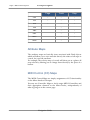
Track groove (GRV)
The GRV value determines how much shuffle is applied to
the track – the range is 0 - 16.
Shuffle means that the steps with an even index in the track
(i.e. 2, 4, 6 … 16) will be played with a delay. Generally, the
larger the GRV amount, the longer the delay that makes up
the shuffle.
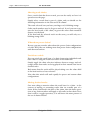
One other intricacy is that the odd GRV values will produce steady
shuffle delays, while the even GRV values will produce delays that are
variable within one 1/192 and which are determined at runtime. The
delay values applied are as follows:
35
Navigation Guide
octopus - MIDI Control Sequencer
IV Track mode
Setting
Delay (1/192)
1
1
2
0-2
3
2
4
1-3
5
3
6
2-4
7
4
8
3-5
9
5
10
4-6
11
6
12
5-7
13
7
14
6-8
15
8
16
7-9
Track MIDI continuous controller (MCC)
The MCC row determines whether or not this track sends MCC.
The “none” flag is represented as four green LEDs in the positions 1316. The value range here is of course 0-127 and please keep in mind
that a value of 0 does indicate a valid controller value.
Two exception are the BENDER and CHANNEL PRESSURE flags.
The BENDER flag is shown as a red dot in position 16 of the MCC
row and is indicating that the track will be sending MIDI pitch bend
messages according to the MCC values stored in that track’s steps.
The CHANNEL PRESSURE flag is indicated by two red dots in the
positions 15 and 16 of the MCC row, and is telling us that the track
Navigation Guide
36
octopus - MIDI Control Sequencer
IV Track mode
will be sending CHANNEL PRESSURE messages according to the
MCC values stored in that track’s steps.
If a track has an MCC parameter value other than “none” (i.e. the 4
green LEDs in the positions 13-16), its chase light color in the matrix
will be orange, while the tracks whose MCC values are set to “none”
have a red chase light.
Track MIDI channel (MCH)
The MCH row indicates the MIDI channel for this track. Default
value for all tracks is channel 1 on port 1. This is represented by a
green light in the 1 position.
Now turn the MCH rotary encoder slowly to the right until you
reach 16. Turning it once more to the right will light the LED in position 1 red. This means that channel 1 on port 2 is now selected.
Therefore green 1-16 assigns a track to MIDI port 1, red 1-16 to
MIDI port 2.
While you are choosing the right MIDI channel for your track, be
sure that the numeric representation is a solid green or red, and not a
blinking one. Blinking representations are related to virtual MIDI
channels, covered in a separate section.
Track data direct entry
Most of the parameter values in the TRACK mode may also be keyed
in using the matrix buttons. Typically a single click will move the ones
value to the pressed value, a double click will set the ones value to
zero and move the tens value to the double clicked value.
Track pitch direct entry
You may have noticed that the pitch value is also indicated in the
pitch inner circle on the right hand side, as you change it and otherwise. Pressing the upper C key in the circle will transpose the track
one octave up; pressing the low C key will first transpose it to the C,
then one octave down.
37
Navigation Guide
octopus - MIDI Control Sequencer
IV Track mode
Track mutators
You may have noticed that the mutator column has several LEDs lit up. They are labeled according to the mutator functions that they trigger.
Signaling
A lit up mutator indicates that it is available. Please
note that all mutator functions described here are also
available from the PAGE mode, as soon as a track is selected.
Track toggle (TGL)
This simply toggles the track on or off. It is equivalent
to muting or un-muting the track when in PAGE mode.
Track solo (SOL)
Pressing the SOL button solo’s the track within its page.
Note that no other pages playing concurrently will be
affected. Pressing it again will un-solo the track in the
page.
Track clear (CLR)
CLR will recall the preset values for the selected track.
Only the MIDI Channel assignment (MCH) will remain unchanged.
The pitch is set to the default value of 60. Note that the
factory pitch assignment can be recalled by calling the
CLR mutator upon a PAGE. If you are at the PAGE
level and grab a Track and clear it, everything is reset.
Track randomize (RND)
This will create a random step pattern in the track, not
affecting the other parameters in the track.
Track FLAT (FLT)
The FLT function is used mainly to combine the pitch
content of several tracks into just one track in the same
Navigation Guide
38
octopus - MIDI Control Sequencer
IV Track mode
page.
This function was conceived as a creative tool and not as a track
space-saving feature, as it may appear at first sight. In some instances
it may be useful as such, but just in some. Please keep this in mind!
FLT will only become available when you have selected two or more
tracks in a page. There is a notion of a destination track, which is always the one from the selection with the lowest index.
Applying FLT to the track selection will fill the destination track
with content from the source tracks.
For every active step in any of the source tracks, you will get the corresponding step activated in the target track. Skipped steps will simply be ignored.
If more than one step is active in the same column across the selected
tracks, the lowest 7 pitches of active steps will get stacked to form a
chord on the respective step in the destination track.
Note that if source track steps contain chords already, only their base
pitch will be considered for FLT. The additional chord data in the
source tracks will be ignored.
The base pitch of the resulting chord will be the lowest pitch encountered in the respective column, with the other found pitches being
stacked on top.
Another detail worth mentioning is the influence of FLT on the VEL,
LEN and STA values of the steps in the destination track. FLT always
carries over the VEL, LEN and STA attributes of the last encountered active step for a particular column/position inside the destination track.
Also something to realize is that FLT is MIDI channel agnostic – you
may FLT different tracks playing on different channels, but the result
will always play on the MIDI channel of the destination track.
With that in mind, let us suggest two best practice usage methods for
FLT. Firstly, before you are applying FLT to your track selection,
make sure the target track is muted.
This way you do not get any double notes playing if the target track is
set to the same MIDI channel as any source tracks. You then can do a
smooth blend-in of the new material, which may be useful when playing live for example.
Secondly, you may want to make sure the target track MIDI channel
is different from any of the source tracks before you apply FLT. This
will effect the obvious – the new material is going to sound fresh right
away. And of course you can use both of these techniques combined
to achieve the result that is best for you!
39
Navigation Guide
octopus - MIDI Control Sequencer
IV Track mode
Track remixes (RMX)
The track remix is used to generate variations of a track without altering it too much. It does have some random elements which are influenced by the value indicated in AMT.
Below is an overview of what the RMX function does:
Influenced map*
Random map
shift
Random step
offset
VEL
+
+
PIT
+
LEN
+
+
STA
+
+
POS
+
*see section on track attribute maps for details on what this means.
Track zoom (ZOM)
The ZOM key is used to zoom into and out of certain views – in this
case it would zoom out of the Track mode and back into the Page
mode. The fact that you are zooming out is indicated by a red LED
light, as opposed to a orange one.
When in page mode, hold one track selector down and press ZOM to
zoom into the track – this has the same effect as a double click on the
track selector. We will talk a bit more about the ZOM mutator when
we describe the MAP mode.
Track Copy and Paste
Copying and pasting tracks has already been described earlier.
A track is selected and copied into an internal clipboard and from
there pasted into the chosen destination.
Navigation Guide
40
octopus - MIDI Control Sequencer
IV Track mode
Track selections
Sometimes it may be convenient to make a change to more than one
track at once. This can be done easily using the same method you
have already seen in the STEP chapter.
Creating track selections
Make sure you are in PAGE mode. Hold down SEL and then press
the selectors of the tracks you would like to add to your selection.
The track selection you have just created will stay active for EDIT
operations until you press the SEL button again.
Also, while the selection is active, you may toggle tracks into and out
of the selection.
Track selection recall
With a track selection active, once you press the SEL button the selection will be de-activated and the SEL button turns red, indicating
that there is a selection that may be recalled.
Generally, SEL will store the last track selection you have made.
Pressing SEL again will bring back your previous selection.
Shortcuts
There is also a quick way to select all tracks in a page at once – simply
double click on the SEL key – you will see the full column of SEL
LEDs light up.
41
Navigation Guide
octopus - MIDI Control Sequencer
IV Track mode
Track chaining
Track chains explained
A track chain is simply a defined sequence of playing tracks from a
page, in a given consecutive order. Track chains are always configured
in PAGE mode and are useful in creating structures longer than 16
steps per page.
Playing considerations
Chain configurations may or may not influence the set track parameters. Each track can be played as it is, or each track’s steps may be
played using the same set of track parameters as its base.
While the preset chain modes were covered in the start-up section,
we shall now look closer at flexible track chain configurations.
Selecting chain members
While in PAGE mode, define first the group of tracks that you would
like to chain by creating an appropriate selection.
Creating a track chain
While the selection is active (blinking orange), press the XXVIII
button to build the chain made up by these tracks.
You will now see that they start playing in sequence. The play sequence is per default top to bottom (i.e. row 9 to row 0).
There are cases when you will see this order changed as a result of
some more interaction with the chain structures inside a page. This
has to do with the way a chain is defined internally.
Under the hood
Every chain has a head and a tail. The head is a track, while the tail
may be made of none, one or more other tracks.
When you create a selection, the top track of a selection will be defined as the head of the new chain, and the other selected tracks will
make up the tail.
Should any of the newly chained tracks have been part of a chain before (regardless if head or tail); they will be removed from their original chain(s) and added to the new one. The original chains will simply
get reduced by the tracks re-allocated to the new chain.
Navigation Guide
42
octopus - MIDI Control Sequencer
IV Track mode
Showing track chains
Once a track chain has been created, you can also easily see how it is
spread across the page.
Simply select a track that is part of a chain, and you should see the
following information in the selector LED column.
The track selected (one you have your finger on) is blinking orange.
Other track members may be lit green and red. In red you can recognize the head track of the chain, in green the other chain members
that are not the head.
If the head and the selected track are the same, you will only see a
blinking orange LED.
What about preset chains?
By now you may wonder, what about the preset chain configurations
on offer? Well, they are nothing more that preset chain configurations
with shortcut buttons.
Track base switch
You can switch the track base of a chain from using individual track
base values to using the track base values of the head track.
Simply toggle the chain selection indicator between orange and red.
orange means that tracks are being played in their natural state but in
chained order.
Red means that the tracks will be played taking over the values held
in the head track as a base reference.
Note that this switch will work equally for preset and custom chain
configurations.
Muting chained tracks
One more thing to mention about the track base for a chain - in the
context of muting or un-muting tracks that are actually part of a
chain. If the chain head is the base of the chain, then the mute operation of any chain members will apply to all tracks in that chain. Note
that it will be a toggle operation, so it will invert the mute pattern of
the set of chained tracks.
43
Navigation Guide
octopus - MIDI Control Sequencer
IV Track mode
Track program changes
MIDI program change
In Track mode, you may have noticed that the Program LED is lit in
orange and the Select LED next to it is lit in green. Also, the numeric
field is not showing the global tempo value anymore, as it does in the
PAGE mode.
We are using that area to edit and send MIDI program changes to
the channel of the selected track.
First, select the MIDI channel you would like to send the program
change on as the track MIDI channel.
Next, dial in a program number, using the rotary encoder
on the top right. Alternatively, you may want to key in the
number of the program you want to select. Once selected,
press Program and you should hear / see the program
change occur.
A couple of side notes are necessary here. First, consider that not all
synthesizer manufacturers use the same numbering scheme for their
programs, i.e. some start counting at 1, some at 0. However, the underlying values are always in the range 0-127.
The Octopus convention is to display values in the range 0-128, where
a value of 0 means that no program change message is sent. Therefore, the program changes are numbered in the range 1-128.
Secondly, a program change message will be sent every time the Program key is pressed in TRACK mode, regardless of all other circumstances.
However, if you keep the Program key pressed while turning the
knob, the program change messages will get sent as you increase or
decrease the PC number via the main knob.
Furthermore, all program changes contained in the tracks of a page
will be sent (once) as soon as that page is enabled for play – either as
part of a cluster, or by manual intervention.
MIDI bank changes
You can also issue bank change messages. This is done simply by
pressing the Select button and turning it orange.
In that case the number displayed will correspond to the bank number, and the bank change message will get sent as soon as you press
the Select button again.
Navigation Guide
44
octopus - MIDI Control Sequencer
IV Track mode
Bank change messages will be sent also when a page is activated for
play, but not when you send program change messages from Track
mode.
45
Navigation Guide
octopus - MIDI Control Sequencer
IV Track mode
Track tempo multipliers
To change a track’s tempo multiplier, go to Track mode, and use the
play buttons with one, two or four triangles in the transport bar.
For example, by double clicking on the >> and >>>> buttons, the
tempo will be set to ½ and ¼ respectively of the master tempo.
The table below shows the available multipliers and the key press
combinations needed to get to them.
Multiplier
Hold
1
1,5
>>
>
>>
>
4
>>
>>>>
5
>
>>>>
6
>>
>>>>
7
> >>
>>>>
8
>>>>
>>
16
>> >>>>
>
1 / 1,5
>>
1/2
1/3
Double-click
>
2
3
Click
>
>>
>
1/4
>>
>>>>
1/5
>
>>>>
1/6
>>
>>>>
1/7
>
>>>>
1/8
>>>>
>>
1/16
>> >>>>
>
Navigation Guide
46
octopus - MIDI Control Sequencer
IV Track mode
The values selected for a track are indicated as follows: In general, red
dots denote multipliers and green dots denote divisors of the cardinality.
For example, having the LEDs of and lit green at the same time denotes a divisor of 5, meaning a track multiplier of 1/5.
Exceptions to the rule include the 1.5, 1/1.5, 8, 1/8, 16 and 1/16 multipliers, covered below.
The 1.5 multiplier is, as it may be obvious already, essential for easy
triplet creation - a triplet being three notes played instead of two.
It is shown as a orange 2 and a red 1. Its inverse, the 1/1.5 multiplier, is
shown as a orange 2 and a green 1.
The 8 multiplier is shown as a orange 4 and a red 2 LED. 1/8 is shown
as a orange 4 and a green 2.
The 16 multiplier is shown as orange 4 and 2 plus a red 1, and 1/16 is
indicated as a orange 4 and 2 and a green one.
Please note that during play, switching the clock multiplier is effective
immediately with no quantization with regard to the master tempo.
Realignment of the tracks may always be done by using the ALN
functionality available.
Note that when the sequencer is playing, the changes of the track
clock multiplier are effective on the next 1/16th beat of the master
clock and not immediately.
This provides better track alignment and improves the general feel of
the sequence without the need to explicitly align after a track clock
switch.
47
Navigation Guide
octopus - MIDI Control Sequencer
IV Track mode
Track auxiliaries
Track chase-light
If you are in Track mode while the sequencer is playing, you will notice a chase-light in the row belonging to the track that you are editing. This is just to help your orientation.
Track view switch
Let’s assume you have now edited a track’s parameters and now would
like to adapt another track’s parameters to some change you have
made. One way is to use ESC or PAGE to exit the track mode and
zoom into the new track as you have seen it before.
A much quicker way is to click in any direction the MIX knob corresponding to the new track, in our example track 6. The display will
instantly switch to showing parameters of track 6.
This function is particularly useful when you are dealing with chained
tracks, where some change in a track may directly imply that the next
track in chain will have to change as well.
Track follow
There is also an automated way of switching the track in the
view – that is the FOLLOW mode.
When Follow is active and you are zoomed into a track that
is part of a chain, the view will always follow the chase light in
the respective track chain, in the sense that it will always
show the track that is currently played by the chase-light.
Activate Follow by pressing the green follow button to turn it red.
Deactivate Follow by toggling it back to green.
Track chord stacks
The steps of a track may be stacked with pitches from a selected scale. To select a scale please follow the instruction in
the section describing the scale mode.
The CHORD stack indicator shows how many notes the
stack will contain. Using the example of a three note chord on a track
containing steps all in C and a selected scale of C major, we would
now have the track play on each set step a chord of C-E-G. This assignment is fixed for all notes on the track.
Navigation Guide
48
octopus - MIDI Control Sequencer
IV Track mode
However, a step that is set to play a chord (see section on step chords)
will not be influenced by the track chord stack. In other words, the
track chord stack will be overruled by step chord settings.
49
Navigation Guide
octopus - MIDI Control Sequencer
V Page mode
V Page mode
Page mode is the level at which you play Octopus in the step sequencer traditional way: the Matrix field is now a field of 10 tracks and 160 steps, waiting
to be played!
Basic operation
We have all along used the page mode as a starting point, from where
we have been zooming into the other elements, notably tracks and
steps so far. It is time to take a closer look at what else is going on in
the PAGE mode itself.
By holding down the PAGE button in the Mode block, generally all
pages that contain data will be displayed with either green or red
LEDs in the matrix.
Exactly one of them will blink orange, pointing out to you the grid
position of the page you are currently in. Please refer to the introductory chapter on general concepts to get an overall view of what the
grid is.
This function is a useful navigation tool, showing you not only what
else is going on in the grid, but also where you are currently with regard to some other content in the grid.
51
Navigation Guide
octopus - MIDI Control Sequencer
V Page mode
The Mixer block
In the previous sections we have talked to a large extent
about what the EDITOR block does – in short, it is used to
change the attributes of a selected entity, where applicable.
The main task of the MIXER block, on the other hand, is
to change a particular parameter of the tracks corresponding to each of the knobs. The parameter that is changed can
be selected directly, using the MIX TARGET button set –
right below the matrix field.
While in PAGE mode, you will see that one of the MIX
target LEDs at the bottom of the matrix is lit - possibly
ATR, since this is the default setting and you probably have
not changed it until now.
Viewing the MIX map
Double click the ATR button. This brings you to the MIX TARGET
assignment, where a parameter can be assigned to the MIX encoder
group.
The Mix Target LEDs light all up, indicating the selected target in
blinking orange. Also, the matrix is showing in every row the value
respective to the corresponding track for the chosen attribute.
This type of display is called a MIX map, showing the behavior of the
tracks with respect to a particular attribute, which can be adjusted
using the MIX encoder block.
As a matter of fact, clicking on any of the MIX target buttons will
open a MIX map view, with the respective values showing, and ready
to edit. We will describe this in the next sections in more detail.
Mix attribute quick assign
A very quick way to assign an attribute to the MIXER BLOCK is to
select the attribute (i.e. to select GRV, press and hold the selector of
row 2), while pressing the MIX button. Or vice versa – hold the MIX
button pressed and press the track selector corresponding to the
wanted attribute.
By pressing the MIX button you will notice that the selected attribute has been changed – the current selected mix attribute is blinking
orange in the selector column.
Navigation Guide
52
octopus - MIDI Control Sequencer
V Page mode
Working with Mix maps
While viewing MIX maps, you can work with a particular track attribute value directly, for all tracks at once. You may tweak the value
of any one track, or apply some functions to all tracks in the page.
Clear
Clear the MIX map using the CLR button – this will reset the MIX
map to default values for each track in the page, all at once.
Randomize
You may randomize the displayed values using the RND button. This
will assign random values to all tracks at once – for the selected attribute of course.
Align
Using the ALN function you may re-order the tracks in the page,
sorting them in the page by the values of the selected MIX MAP attribute. The sorting will be done such that the track with the highest
value will be placed on the top row. Try it out!
Copy / Paste
Finally, if you have composed a page whose MIX map you would like
to replicate, you may use the CPY / PST functionality to replicate
that attribute assignment across the tracks.
For example, assuming you have a page whose pitch structure creates
a certain mood or harmony; you can apply the same mood to an entirely unrelated page or pattern, by simply copying the PIT map from
one page to the other.
53
Navigation Guide
octopus - MIDI Control Sequencer
V Page mode
Mix map targets
Going back to editing, there are three classes of targets: attributes
(ATR), preset MIDI CC’s (any of VOL, PAN, MOD, EXP), and
MIDI Control Maps (MAP 0-5). Some explaining is due here.
Attributes
If the ATR type is selected by a double click, the SEL buttons will
light up green, indicating that any of them may be selected. The already selected attribute will blink orange.
The matrix will show the value relevant for the respective rows.
All rotary knobs act upon the same attribute on their respective
track. For example if PIT (pitch) is selected, every rotary will change
the pitch of its assigned row.
Preset MIDI CC’s
The MIDI CC’s behave the same as the ATR targets. The CC’s used
are: VOL (7), PAN (10), MOD (1), EXP (11).
MIDI Control Maps
Using a MIDI Controller Map, any MIX knob can be assigned an individual CC on a chosen MIDI channel.
As an example, double click on MAP 0 to select MIDI Controller
Map 0. You will notice that the AMT button will blink orange indicated that AMT is selected. The matrix shows the per-track AMT
values, which is really the CC amount set on each of the tracks.
Press the MCC button. Here the Matrix shows the actual Midi Continuous Controller assigned to each of the tracks.
You can modify the CC for every individual track using the MIX
knobs. Remember that four green LEDs in positions 13, 14, 15, and 16
indicate that no CC has been assigned.
Now press the MCH button. This view allows you to assign the
MIDI channel on which the CC signal is sent.
Note that this is not the MIDI channel of the Track – the track’s
MIDI channel is an entirely independent parameter.
Finally, the settings that you have just made are stored as a MIDI
Controller Map. There is a total of 6 MIDI Controller Maps, and
Navigation Guide
54
octopus - MIDI Control Sequencer
V Page mode
they are global. This is useful because you can have MIDI map operate beyond the context of a page, as they fulfill a global function.
Playing MIDI Controller Maps
MIDI Controller Maps may be edited and operated directly from
both the GRID and the PAGE level.
Select one of the MIDI Controller Maps, 0-5. You will see that the
LED for the corresponding map is lit orange to show that it is currently active.
Timeout
The MIXER block may be used at any time during PAGE mode operation. In order to make the effects visible, once you operate any of
the MIX encoders in PAGE mode you will see its value displayed
briefly in the corresponding matrix row.
The value will disappear shortly after you have performed the last
click, to clear the view for the regular contents of the track.
55
Navigation Guide
octopus - MIDI Control Sequencer
V Page mode
EDIT state
Octopus provides a quick way of previewing steps, in the
sense that you can immediately hear what they contain, and
how they would play under the chase-light.
This is particularly interesting of course when you are tweaking something to sound just right.
By default, in PAGE mode the EDIT LED button lights steady
green. Click on it once to toggle it to blinking orange.
When the EDIT LED is lit steady green, everything behaves as you
know it: the step buttons toggle the step states. When turned to
blinking orange you are in the EDIT state.
To return to the default state (steady green), press the EDIT button
twice (again - twice, and not double-click!).
Editing Steps
First make sure the EDIT LED is orange.
Now press some buttons in the matrix. You will notice that no steps
will be set (as we have done it before), but that the MIDI data of the
steps is played out of the MIDI port as it is.
Grab a step and now tweak its attributes, for example pitch, to take
the most obvious one: you will hear that with every click of the encoder the steps is re-triggered and played such that you can hear the
change in real time.
The step velocity is shown and editable in the numeric quadrant of
the outer circle, the pitch in the inner circle.
The step length may also be adjusted in the matrix, by pressing another button at a distance to denote the length in 1/16th intervals.
Editing Tracks
Pressing the track selectors in preview mode will produce a result
similar to the steps buttons.
The note played will basically reveal the tracks velocity and pitch settings, producing a result equivalent to having a non-modified step
playing in that track.
Navigation Guide
56
octopus - MIDI Control Sequencer
V Page mode
EDIT PERFORM state
An alternative and quite rewarding mode of working with a step sequence (depending on your style and preference) is that of tweaking a
set sequence of steps in realtime, while the sequence keeps playing.
You can also do this to some degree without a special mode, but
EDIT PERFORM takes this to perfection.
EDIT PERFORM is actually similar to the EDIT state, with the exception that no MIDI data is transmitted when you operate on the
matrix. This is particularly interesting for the Berlin School type of
performances.
By default, in PAGE mode the EDIT LED button lights
green. Click on it once to toggle it to blinking orange, and
once more to make it blink green.
Again, when the EDIT LED lights steady green, everything
behaves as you know it: the step buttons toggle the step states. When
EDIT blinks orange you are in EDIT mode, and when EDIT blinks
green you are in EDIT PERFORM mode.
57
Navigation Guide
octopus - MIDI Control Sequencer
V Page mode
Editor ATR state
In Page mode, an ATR may be temporarily assigned to the EDIT
knob group.
Engage
This is done by holding the selector of the respective attribute to select the attribute, and at the same time pressing the
EDIT master button to make the actual assignment. The
indicator for the Knob group will light orange, indicating
activity.
In this mode the EDIT knobs will behave just like another group of
MIX knobs for the just selected attribute.
Disengage
Pressing the EDIT master button once will cancel the assignment
and return to the legacy mode of operation.
Navigation Guide
58
octopus - MIDI Control Sequencer
V Page mode
Editor MCC state
The EDIT button has one more state – that is the MCC send state.
This is used to make the editor knobs send MCC data.
Sending MCC data
The MCC amounts sent will be on the MIDI channel and controller
chosen in their corresponding tracks. See section on Track Attributes
if you don’t remember the details for setting up Track MIDI CCs.
Engage
To activate the MCC state, double-click on the EDIT button turning
it red.
Disengage
To deactivate the MCC state, just press the EDIT button once.
59
Navigation Guide
octopus - MIDI Control Sequencer
V Page mode
Page mutator functions
When in PAGE mode, holding the PAGE key pressed will make
some mutator functions available for the page itself – the expected
results should be quite obvious. Applying them is a matter of pressing
the appropriate mutator button.
TGL
Pressing TGL will toggle the page play status in the grid.
SOL
Page will be solo-ed and un-solo-ed. When solo-ed, the Page LED in
the circle will blink green as opposed to orange
CLR
Using CLR on a page will reset the page to the default page values,
including resetting the tracks to their forward moving direction.
RND
This will fill the page with random step patterns on all tracks. Note
that the track attributes are not affected, just the step patterns.
RMX
All tracks in the page will be applied the RMX function. See track
mode for details.
CPY
Page can be copied to the copy buffer. The copy operation will include the chain configuration local to the page at the time of copy.
PST
Copy buffer will be pasted into the present page position.
Page POSITION in GRID
Another function available is jumping to another page of the grid. As
you press the PAGE key you will notice a orange LED blink in the
Matrix. This indicates the position of the current page in the grid.
Switching pages
Holding PAGE pressed and pressing a matrix key other than the one
blinking and in any row other than row 0 will take you directly to the
page associated with that key in the grid.
This is especially useful when you are working on musical structures
spanning several pages.
Navigation Guide
60
octopus - MIDI Control Sequencer
V Page mode
Bank view
When in PAGE mode, by default you see a green lit Select LED in
the top right quadrant of the circle, along with the orange Tempo
LED.
They indicate the two available modes for the main knob and the
numeric field: one of them (default one) is to show master tempo in
the numeric filed of the circle, the other one is what we call the bank
view.
A bank is the set of 16 pages that live on the same Grid row, and
which are mutually exclusive at playtime, meaning that only one page
may play per bank, at any time.
Entering bank view
Pressing Select will allow you to see in the numeric field the banks
that are currently playing (i.e. contain a playing page) as green lit buttons.
The orange blinking one is the bank currently in your matrix editor.
Note that this says nothing about which column in the bank is currently playing, as a bank only says something about the Grid row that
a page resides on.
Pressing any of the green lit buttons will take you directly to the currently playing page in that bank.
Turning the main knob will incrementally take you through the playing pages.
Exiting bank view
Press the Tempo button to return to the standard Tempo display.
61
Navigation Guide
octopus - MIDI Control Sequencer
V Page mode
Play mode
The PLAY mode provides the capability to try new things in a page,
in a non-destructive manner.
Activating the PLAY mode is equivalent to taking a snapshot of the
currently playing page in a bank for later recall, in case the results of
your editing do not live up to your expectations. Notably, the play
mode snapshots include track mute patterns of the respective pages.
Also note that engaging the PLAY mode may be done from both
page mode and from grid mode.
Engaging play mode
To activate the PLAY mode press the green PLAY button
in the MODE block and you should see it blink orange.
Also you will notice that the Program button will be lit
red.
Now make all the changes and editing that you need to make to your
page until you reach a point of satisfaction, or possibly slight regret.
Make changes permanent
To keep the page, simply press Program to make the changes permanent.
Discard changes
To discard the changes, press PLAY again, exiting the PLAY mode
and recalling the state of the page from just before you started.
Note that upon stopping the sequencer you will also lose any changes
made during PLAY mode.
Navigation Guide
62
octopus - MIDI Control Sequencer
63
V Page mode
Navigation Guide
octopus - MIDI Control Sequencer
VI Grid mode
VI Grid mode
Grid mode is the level at which you control at large amount of MIDI data at
once: the Matrix field now gives you instant access to 144 pages!
Basic operation
The GRID mode will typically be the mode used for controlling a
large amount of sequence data at once.
For example, sets of active pages can be stored and recalled using the
page set snapshot feature, together with the function of saving the
full instrument state for recall even after a power off or reset cycle.
Entering Grid mode
To enter the GRID mode simply press the green
lit GRID button in the MODE selector section
of the front panel.
Now start the sequencer. You should see the note
inner circle being filled up with a progress bar.
Global master clock
This progress bar really indicates the position of something you may
think of as the global master clock of Octopus.
This clock runs through a cycle of 16 steps after which it starts over.
This is the lowest-level Octopus clock and the only interaction you
have with it is when you change the master tempo.
Where are you from?
As a simple reference and reminder as to which page you came from
into the GRID, you may press the PAGE button in the MODE block
and you should see a orange blinking light at the respective position.
Note that this shows something you can think of as the “page in focus”, which changes however as soon as you start operating on pages
from the GRID mode, as we shall see described in this chapter.
65
Navigation Guide
octopus - MIDI Control Sequencer
VI Grid mode
Page operations
In GRID mode, you are looking at all your pages at a glance: every
button in rows 1-9 represents a page, and the LEDs indicate the
status of the pages.
A notion we introduced earlier is that of banks: a bank is the set of
pages which exist in the same Grid row, and who may play in a mutually exclusive way - i.e. at most one page per bank will play at any
given time.
Matrix representation
OFF means the page is empty, green means the page has some content and is playing, red means the page does have some content and is
not playing.
Later on you will get into the situation where page LEDs may turn
orange, indicating that the page is queued up for play.
Grid EDIT and live modes
Furthermore, you should take quick notice of the EDIT LED. It
should light orange to indicate that we are currently operating in Grid
EDIT mode. By the end of this chapter we will have seen the Grid
live mode as well. Let’s stay focused on what we have, for a moment..
Zooming into pages
You will see that the ESC LED is lit up in GRID mode. This may be
a quick way to return to the page you just came from – assuming it is
still the page in focus, i.e. the last page that was operated on from the
grid mode, or the one we have just zoomed out of.
In order to get back into a page, any page, you would either double
click on the button corresponding to a page, or simply select the page
by holding down the PAGE mode button and then pressing the page.
Alternatively you may also press the ZOM button while pressing the
page button. What you finally choose is really up to your personal
style and workflow.
Page considerations
By telling you how to leave the GRID mode, we have already given
away a lot about how to work with pages in the GRID; hopefully just
Navigation Guide
66
octopus - MIDI Control Sequencer
VI Grid mode
as you would expect. The key principle here is to grab and operate,
but this should be no surprise this far.
After zooming into the page as indicated above, you enter Page
mode. If the PAGE mode LED is flashing red, the selected page is
not active, i.e. it is not playing in the Grid. To make it play, hold the
PAGE button and press TGL to make it active.
67
Navigation Guide
octopus - MIDI Control Sequencer
VI Grid mode
Page clusters
So far we have only played pages one by one. There is a way to make
pages play consecutively; this allows you to create structures longer
than one page alone has to offer.
Building clusters
In order to play two or more pages consecutively they have to be
situated next to each other in the GRID. You can achieve this easily
by using CPY / PST / CLR mutator functions in order to create what
we shall call page clusters.
A page cluster is therefore a group of two or more adjacent pages surrounded by either empty pages or grid margins.
Cluster activation
Create a page cluster consisting of three pages in a row of your
choice. Once the cluster is built, make sure the sequencer is playing
and toggle one of the pages in the cluster to green (i.e. make it play).
The page will keep on playing.
Activate cluster play for the row in which the cluster exists by pressing the SEL button of that row once – toggling it from red to green.
When green, you will notice that once the currently playing page is
finished playing the next page in the cluster starts to play and so
forth.
Clustering side notes
In total you may set up to 16 pages for consecutive play (maximum
size of a cluster).
Assuming that all pages have all their tracks chained up (10 tracks per
page) this means we get a total of 160 x 16 = 2560 steps playing consecutively.
Add to that the capability of allowing any page to be repeated up to
16 times – let’s look at that next.
Navigation Guide
68
octopus - MIDI Control Sequencer
VI Grid mode
Page play parameters
Page repeats (STA)
Page clustering can become even more fun, as
you can set the number of repetitions individually for each page. For example, page A can play
4 times, page B 2 times and page C 1 time. The
number of repetitions can be any value between
1 and 16, where 1 is the default value.
In order to set the repetition value for a page,
simply keep it pressed and select the number of repetitions in row 0 –
for any number between 1 and 16. You may press on a page’s key and
you will see the repetitions value along with the currently left number
of repetitions for play.
Another way of modifying a page’s number of repeats is to hold the
page in the grid, while turning the STA knob in the edit block.
Page length (LEN)
When pages play, they are set per default to play 16 step positions,
after which they play another 16 steps and so on. These rather natural
sixteen 16th positions make up what we call the length of the page,
i.e. how many positions until the track “wraps around”.
However this value may be changed to a number higher or lower than
the natural 16. For example, assuming length 12 for a modified page
playing along with a reference page with length 16, the modified page
will play its first 12 positions, after which it will play once more its
first 4 positions. After that it will start over from position 1 and so on.
Let’s see briefly how this may be used: As we have seen, clustering
pages is a way to create structures spanning more than one page. If
you have worked with pages that contain tracks of different lengths
and had these be part of clusters, you may have wondered what determines the moment of switching from one page to the next.
To set the page length of a page, make sure you are in GRID mode,
and from there press and hold the button of the page whose length
you want to read or modify. When pressing the page button, notice
that the SEL LED in row 0 will be lit and can be pressed to change
colors between red and green. Make sure to set it to green.
The default is a red LED in the first position of row zero. This indicates that the page is playing a full 16-step cycle. In order to change
that, use the row zero buttons and click / double-click them to
achieve the desired result. Note that the maximum length of a page
can be set up to be 8 cycles, or 128 step lengths.
69
Navigation Guide
octopus - MIDI Control Sequencer
VI Grid mode
Note that to create a page length of less than 16, you need to doubleclick the 1 LED to turn it off, then single click on the keys 1 to 15.
Another way of modifying a page’s length is to hold the page while
turning the LEN knob in the edit block. Simple as that!
One final remark on page length: a value less than 16 (a full note cycle) will re-trigger the page after every time the page has finished
playing its designated length. LEN values of 16 positions and higher
will not re-trigger the page, allowing you to create longer-evolving
structures.
Navigation Guide
70
octopus - MIDI Control Sequencer
VI Grid mode
Page follow
At any time during play in GRID mode you may zoom into any page
you would like by the methods described already.
If the page is part of a cluster and some page in the cluster other than
the zoomed one is playing, you may want to see the position of the
chase-light in the cluster.
Press the green Follow key to enable the follow page function, turn ing it red. You will notice that the matrix display
will always switch to the page that is currently playing, essentially following the chase-light as it moves forward through
the pages of the current bank.
This is particularly useful when you are working on structures longer
than one page. Pressing the Follow button again will freeze the view
on the page currently showing.
An easy way to remember the color coding could be:
Red: stick to the red chase-light, green: stick to the green steps.
71
Navigation Guide
octopus - MIDI Control Sequencer
VI Grid mode
Navigation Guide
72
octopus - MIDI Control Sequencer
VII Performance tools
VII Performance tools
This section presents some tools that are especially useful in performance
situations, allowing for unmatched freedom in your workflow!
Working with pages
This section is assuming we are working in the GRID mode, where
we have control over the behavior of individual pages. Please switch
to GRID mode if you are not there already.
The Matrix field keys in rows 1-9 represent pages. At any given time,
only one page in every row (bank) can be playing. So there may be up
to 90 tracks playing concurrently.
Page activation
In order to activate a page for play you just hold it pressed and press
TGL. Repeat the procedure to make it not play any longer.
TGL will have an effect on a page only if the page is not empty (i.e.
lights red or green).
When you grab a page, you will also see that there is a set of mutators
available for the page. Their semantics is very similar to that of
tracks. You may want to experiment a bit without knowing too much
about the details of their implementation. For the time being just
make sure the page you are working on is also playing.
Page mutators
SOL
Will solo the page in the entire grid – pressing SOL again will un-solo
it. Only one page can be in solo mode at any one time.
Groups of pages playing concurrently are handled by the page sets
feature described below.
CLR
Will rest the page to default, so make sure you are not calling CLR on
a page whose contents you would rather keep.
RND
Will randomize the contents of the selected page, giving a good playground to inspire you.
73
Navigation Guide
octopus - MIDI Control Sequencer
VII Performance tools
RMX
Will call the Remix mutator function on each of the page’s tracks.
ZOM
We have looked at already – it takes you into the page in question.
CPY
This will copy the page to an internal buffer for later PST operations.
Once a CPY operation has taken place you will see that the PST operation becomes available.
For convenience (explicitly and consciously against consistency),
holding the PAGE MODE button in GRID mode and pressing the
button of a page in the grid will zoom into that page.
Page transposition
When a page is selected in the grid, you may notice that the pitch
circle lights up. It indicates the page’s pitch offset and lets you modify
it, in order to transpose the entire page content in one place. Alternatively you may use the PIT encoder to adjust it as well.
To transpose the page by one full octave respectively, you may use the
High C and Low C keys in the circle.
Page velocity (VEL) factor
Similar to the factors we see in conjunction with the track attribute
maps, there is a page velocity factor that may be adjusted from the
grid mode. The page velocity factor is a master determinant of the
velocity produced by note content in a particular page. Assuming the
patch on your sound source is velocity sensitive, you should be able to
easily create fade-ins and fade-outs using this functionality.
Select a page in the grid, and while selected, turn the VEL encoder.
The numeric quadrant of the outer circle will display the factor value.
Page switch modes
When switching pages in and out of the grid you will usually want
them to start playing right on the beat – and they will (provided the
progress bar of the master clock is lit red).
Immediate switching
You may also choose to have toggled pages start and stop immediately as you operate the TGL button. For that you have to make sure
that the master clock progress bar is lit green.
Navigation Guide
74
octopus - MIDI Control Sequencer
VII Performance tools
To toggle between red and green you just press the Tempo button at
the top right of the outer circle and you should see the color of the
master clock progress bar change accordingly.
In summary, there are two page switch modes, which we call “o’clock”
and “immediate”. To toggle between them simply press the Tempo
button. O’clock is denoted by a red master clock indicator, immediate
by a green one.
Realigning pages
When operating in the direct toggle mode (green progress bar) it is
easy to get pages to play out of sync. In order to get them all aligned
back to the master clock you can press the ALN button, like you did
for tracks inside a page, earlier on.
Grid mode page mutes
In GRID mode, when no page is grabbed (i.e. held down), the mutator buttons take on a similar role to the one that the main MUT button has in PAGE mode - that is, toggle between a stored track mute
pattern and back, in the page that is momentarily playing in the
GRID.
As such, the colors of the LEDs should become clear: an unlit LED
means there is no page playing, or the page does not have a mute pattern - neither stored nor active.
A green LED means there is a stored mute pattern that may be activated, and a red LED means that there is a mute pattern active in the
page.
Finally, pressing the main MUT button will toggle all mutators, i.e. all
green ones will be turned red, and vice versa, with the implications
already described above.
Grid live mode
As mentioned earlier in the Page operations section, the page operations you have learned so far were part of the EDIT mode. As the
name suggests, this mode is suited for applications where you work
with the material in an editing sense.
The Grid live mode is more suited in the cases where you are playing
your material live, hence the name. In Grid live mode the matrix buttons will act as toggles for the respective pages. This provides more
immediate and intuitive handling of material in live situations.
Switching to Grid live mode is quite easy: make sure the EDIT LED
is off. If it is lit orange (default state) press it once to turn it off.
75
Navigation Guide
octopus - MIDI Control Sequencer
VII Performance tools
Operating in Grid live mode is easily explained. In principle, the page
buttons now act as page toggles, much similar to the way things work
in page mode, where buttons act as step toggles. Confused?
Pressing a page button that is red (page is not playing), will turn that
page on. Pressing the button of a playing page (green) will turn that
page off.
Bank mute toggles
In GRID mode, the buttons in the MUT column act as bank mute
toggles. Pages in muted banks will continue playing in sync with all
active ones, but their output will not be sent out to MIDI.
This provides more immediate and intuitive handling of material in
live situations.
Navigation Guide
76
octopus - MIDI Control Sequencer
VII Performance tools
Working with step selections
Inverse step selection editing
In PAGE mode, active step selections are edited using the EDIT encoders for the respective attribute.
Additionally, when a step selection is active, the steps that are not selected, in the tracks that contain selected steps, may be edited as well,
using the MIX encoders of the respective attribute.
For example, assuming a step selection is active with steps selected in
tracks 2 and 4, the EDIT encoder PIT modifies all steps in the step
selection, while the MIX encoder 8 will modify the pitch of all steps
that are not currently selected in the tracks 2 and 4.
Step selection stores
In PAGE mode, active step selections are stored for later recall in one
of 5 stores available per page. This allows to group steps and modify
them at once beyond track boundaries.
The stores 1-5 are accessible while a step selection is active via the
buttons labeled 1,2,3,4,5 in the MIX TARGET row below the matrix.
Just to give you an example..
To make a step selection hold the SEL button pressed and click on at
least one active step (green) in the page. You should see the selected
step blink green and the current selection indicated by the blinking
light in the MIX TARGET row. By default it should be 1.
Now press the 2 key in the MIX TARGET area and the selection will
disappear. This is because step selection 2 is empty. Let’s fill it. Press
and hold the SEL button and select another step or more and watch
them blink.
Press the 1 in the MIX target area and you should see your previous
selection blink active. You can toggle between your selections at will
using the MIX TARGET buttons, and use the encoders to really bend
your material.
77
Navigation Guide
octopus - MIDI Control Sequencer
VII Performance tools
MIDI Control Maps
As already introduced in the section on PAGE mode, you may assign
MIDI Control (CC) functionality to the MIX encoders.
This is useful when you are looking to control some parameters of a
more global nature, such as certain instrument volumes, or other
things that are not specifically bound to a particular page.
There are 6 MIDI Control Maps. You may switch between them directly by pushing their corresponding buttons in the MIX target section of the panel.
Note that unlike in PAGE mode, when you use MIDI Control Maps
in GRID mode, the modified values are not shown.
Navigation Guide
78
octopus - MIDI Control Sequencer
VII Performance tools
Page sets
When you have a certain number of pages in the GRID, which you
are tweaking and playing in various combinations, you will eventually
find combinations that you would like to recall quickly.
Concurrent page activation
Octopus can store the pointers of all active pages at a given time in
what we term a Page Set. Activating or switching between Page Sets
can then be done by the press of a button at playtime.
The operation is equivalent to and a shortcut to toggling a set of
pages on – with all the rules that apply: only one page per bank will
play, banks determine cluster behavior, page length is determined in
the pages.
Working with Page Sets
Simply activate in the matrix the set of pages that you would like to
store for recall.
Once they are all playing, press and hold the green SEL button, while
you press any of the 16 buttons in row 0. The buttons in row zero
represent memory slots for storing your page sets.
You will notice that once you have stored a set, into a slot, its corresponding LED turns green – indicating that the set of that slot is now
playing in the grid.
Now press the button of an empty slot – you will see that all pages
stop playing, the slot LED lights orange (it is empty), and the previously saved slot is lit red – because it is not playing.
Pressing the red slot button will recall the page combination you had
defined before for this particular slot.
79
Navigation Guide
octopus - MIDI Control Sequencer
VII Performance tools
Grid-Track mode
The GRID-TRACK mode may be imagined as a sub-mode of the
GRID Mode. The GRID-TRACK mode provides most of the GRID
functionality described above, allowing a different view on your
MIDI data.
Here, matrix buttons represent tracks (as opposed to pages) and have
the functionality of track selectors, as described for the PAGE Mode.
We may refer to them as virtual track selectors.
Entering the Grid-Track mode
To enter the GRID-TRACK mode, enter the GRID mode first (by
pressing GRID) and then press the green-lit TRACK button.
The TRACK button will blink orange, and the GRID button will
stay lit in orange. This indicates that you are in the GRID-TRACK
mode.
Virtual track selectors
The Matrix will slightly change its contents and some explanation is
necessary to what it now conveys.
For each page playing in the GRID, you will see a lit bar of 10 LEDs,
from position 4 to position 13, leaving three blank columns of buttons
on each side.
Each lit button acts as virtual track selectors and the LEDs indicate
the toggle state of the corresponding track.
Hands-on
As an example, let’s assume there is only one page playing in the
GRID in bank 1 of the grid and no tracks are muted in that page. You
should see a bar of 10 green LEDs in row 1, positioned in the centre
of the row (3 unlit LED’s to each side of the 10-LED bar).
Working with tracks
Moving from here is easy: press and hold any of the virtual track selectors and you will see that two mutator functions become available:
TGL and SOL.
Also, the EDIT block indicator blinks orange, as you may use the encoders to modify the track selected via the virtual selectors. This
should come pretty naturally (or so we think).
Navigation Guide
80
octopus - MIDI Control Sequencer
VII Performance tools
When exactly one track is selected in GRID-TRACK mode, the
pitch of that track becomes visible and editable in the inner circle,
just as we have seen it in PAGE mode.
Quick track toggle
Sometimes all you want to do in GRID-TRACK mode is to toggle
tracks on the fly. There is a quick way to do that by holding any button that belongs to columns 1-3 or 14-16 while pressing a virtual track
selector. The virtual track selector now directly toggles the mute
status of the respective track.
Zooming into tracks
You may do much lower-level editing of tracks, simply by doubleclicking a virtual selector to enter TRACK mode for that track, i.e.
zooming into that track. And you know your way around there already.
To return from TRACK mode to GRID-TRACK mode simply press
the GRID and TRACK mode buttons at the same time – this proved
to work well.
Grid-Track live mode
The GRID-TRACK live mode is much similar to the live mode in
Grid mode. It is activated by pressing the EDIT button LED such
that it is lit green.
When in live mode, the matrix buttons will act as toggles for the respective tracks. This provides more immediate and intuitive handling
of material in live situations.
Leaving Grid-Track mode
In order to exit the GRID-TRACK mode, press either the GRID or
the TRACK button. Both of them will simply take you back to
GRID mode.
81
Navigation Guide
octopus - MIDI Control Sequencer
VII Performance tools
Navigation Guide
82
octopus - MIDI Control Sequencer
VIII Musical tools
VIII Musical tools
The section provides descriptions for tools that are of value on the musical
side of things, such as chords and scales.
Step chords
Steps may play more than one pitch at a time, effectively forming
chords. Chords can be directly programmed in, or directly recorded
from, a MIDI keyboard (see the section on MIDI IN Recording)
into a step.
The next section will assume we are working in STEP mode. To follow along, please make sure to enter STEP mode before we move on.
To set the stage, while in STEP mode, notice the CHORD button
block at the bottom right of the front panel. By default the single
note chord button should be lit orange.
Chord ground rules
Step chords are formed of up to 7 notes which may range over up to
three octaves. The chord is made up of the step pitch as the base and
additional notes that are stacked “on top” and which are always
higher than the base pitch. This means of course that changing the
PIT offset of the step will also transpose the chord.
The chord display should be read as follows: the base pitch of the
step blinks orange. Notes within one octave (12 semitones) of the
base pitch light orange. Notes in the second octave up light green,
and notes in the third octave up light red.
A note may not be part of the chord at the same time in several octaves. To toggle the notes manually in and out of the chord following
toggle sequence applies: off > orange > green > red > off.
Playing chords
To build a chord on a step proceed as follows:
Press and hold down the CHORD button that corresponds to the size of the chord you will build. Assuming
you want to build the chord C-E-G you would hold
down the three-note chord button.
83
Navigation Guide
octopus - MIDI Control Sequencer
VIII Musical tools
Next, use the octave circle to enter notes
into the chord up to a cardinality of
seven. Entry and display corresponds to
the chord ground rules above.
When you are done entering the chord,
release the chord button. You should see
that the cardinality of the step chord is
now indicated by the appropriate chord
LED - in this case the three-note chord.
Every time the step is played, you should
hear the chord that you have programmed in. To remove the chord
from a step, simply remove all “extra notes” from the chord. The base
pitch will not be removable.
Steps that are set to play chords will be displayed by a orange dot
while in PAGE mode. Steps that play only single notes are green.
Step polyphony
Step polyphony offers an exciting playground for experimentation
and variation, especially with regard to dynamic pitch variation, as in
random note picks from the chord pool.
Assuming you have built the C-E-G chord as described earlier, let’s
think about polyphony. The natural polyphony of the step is of course
3, since it is playing 3 notes at the same time.
However, polyphony may be adjusted independently of step chord
contents, i.e. without changing the number of notes in the chord.
The step chord size, i.e. the number of notes in a step,
is indicated by a red LED in the chord block. The step
polyphony is indicated by a green LED in the chord
block, When chord size and polyphony are the same
you see an orange LED in the chord block at the respective position.
Random note picks from chord pool
A step whose polyphony and chord size are the same, will play a
chord in the traditional sense, as you would expect it.
When step polyphony and chord size are different, the number of
played chord notes is always the smaller of the two values (i.e. chord
size or polyphony). Here the actual notes are chosen at random from
a pool composed as follows:
Navigation Guide
84
octopus - MIDI Control Sequencer
VIII Musical tools
- When chord size is greater than polyphony, the note pool is made
up by all notes that make up the chord.
- When polyphony is greater than the chord size, the note pool is
made up by the chord notes plus a number of rests (“empty” notes).
The number of rests is given by the difference between the polyphony and the chord size.
Example:
Chord is C-E-G, therefore chord size is 3:.
- A polyphony of 3 will consistently play the chord C-E-G.
- A polyphony of 2 will play two elements picked at random from the
pool {C, E, G}.
- A polyphony of 5 will play 3 elements picked at random from the
pool {C, E, G, rest, rest}
Strumming chords
To strum a chord, zoom into the step containing the chord,
hold any of the chord buttons pressed and turn the main
rotary clock-wise. You will be able to set a strum level between 0 and 9 shown as green values. This also means that
the chord will be strummed up.
Turning the main rotary counter-clockwise will show the
red values -9 to 0, which are indicating that you are now
strumming the chord down.
Octopus comes with a preset strum configuration which affects the
note start values. The strum effect increases exponentially with the
strum level chosen.
85
Navigation Guide
octopus - MIDI Control Sequencer
VIII Musical tools
Step phrases
Step phrases are a tool to quickly and greatly enrich a step. A step
phrase is a group of notes that are triggered as an “avalanche” by a
step, based on the pitch of that step.
Assigning a phrase to a step is very simple: from Page mode, double
click the step to enter Step mode, select GRV as the attribute to edit,
and dial in the phrase index using the main encoder.
You may browse through the preset phrases one by one first, before
deciding what would suit your mood or material. Once you are happy
with a particular phrase, you can switch view to the POS attribute,
which determines the time compression factor of the step’s phrase. A
low POS value means high time compression, and vice versa.
There are three banks of preset phrases available: green, red and orange banks with 16 phrases each. They are grouped as follows:
Green: note delays, simple and rhythmic ones
Red: arpeggios and intervals triggered by the note
Orange: combinations of non-deterministic values for STA, VEL, and
PIT. For example, to delay a step by an undetermined number of
ticks, select one of the first 4 phrases in the orange bank.
So far we have only talked about preset phrases. In case you were
wondering - yes, you may edit the phrases yourself too, in any way you
like. How that is done is explained in a separate section.
Having some fun with phrases..
Select a phrase for a step and its appropriate time compression (POS)
value. While still in Step mode, press the Copy key to copy the step
to the copy buffer. In the bottom row select another step from the
track by pressing its key. If the step is empty you will see it blink red.
Now press the Paste button, and you have made a copy of the original
step, including the phrase.
Move on and set a pitch offset for this new step (PIT encoder), and
maybe even a different time compression. Repeat the procedure as
you see fit.
Within a few clicks you may end up with a fairly complex structure,
which you probably wouldn’t have come up with that quickly otherwise.. Enjoy!
Navigation Guide
86
octopus - MIDI Control Sequencer
VIII Musical tools
Musical scales
Each page can be associated with a particular musical scale. Once
that association is done and a scale is active, all page notes are forced
to play in the chosen scale.
Force to scale
Force to scale for a page is enabled by going to PAGE
mode and simply pressing the green lit SCALE SEL
button. Coming from the default state, you will see
its LED turn red and all scale notes light up, with the
exception of upper C.
Conversely, force to scale is disabled by pressing the red SCALE SEL
button, which indicates that force to scale is engaged.
So, in general, the red LED of SCALE SEL is indicating that the page
pitches are forced into the scale, a green LED indicates that the page
is playing the pitches as they are.
The lower C LED is also lit orange. What you see here is that all
notes are selected in the scale, and that C is the base tone of this
scale. Let’s now modify the scale to get more interesting effects:
Composing scales
While having force to scale active as described above, press the Select button (in
the outer circle, button XIV) and it should
blink orange, while the Chr. scale LED is
lit orange.
This picture is telling us that the chromatic C scale is currently active, but that
we may select any notes in our current
scale. The Select button you have just
pressed is used to let you select the notes
that you would like to add to your scale.
Now press any of the note keys in the scale circle to toggle the corresponding notes into and out of the scale, putting together any scale
you like. Once you are done selecting the scale notes, you may press
SCALE MOD again, and now you can modify (again) the base pitch
of the scale you have just selected.
Another way to select a scale is to press any of the scale buttons in
the outer circle, to get the scale structure associated with their label,
always on the base tone indicated by the orange LED.
87
Navigation Guide
octopus - MIDI Control Sequencer
VIII Musical tools
Changing the scale base
In order to change the base tone, press the SCALE MOD button to
enter the scale modulation mode. Here you may select any of the current scales tones as the new scale base.
As you change the scale base you will see the scale signature carry
over to the new base as well.
Scale cadence mode
Another way of operating the Scale data is to combine it with the
CAD functionality. What this means is that any changes done to the
scale will translate into immediate mappings onto the track pitches in
the page at hand.
To activate the SCALE CAD, please activate force-to-scale if not already active, and then press CAD (so it blinks red indicating operation).
In order to make the effect clearly visible (on top of audible) you may
also want to select the MIX mode for the track pitches (double click
on the ATR key in the MIX TARGET field, then select PIT).
Now modify the scale as described and you should see the changes to
the track pitches as they materialize in the matrix.
Disabling the page scale
You may want to have your page notes forced to the selected scale,
but not see the details behind that and also prevent any unintended
changes to the scale, essentially locking it.
In that case, while in SCALE mode, press ESC to leave the page
forced to the scale, but to exit the SCALE mode. You will notice that
the SCALE SEL LED will blink orange, indicating that the page is
forced to scale. To go back into the scale edit mode, simply press the
orange blinking SCALE SEL LED.
The grid scale
The GRID may be assigned a scale, in the same manner that a scale is
assigned to a page, except the GRID scale will act globally.
To operate the GRID scale, switch first to GRID mode. Use the
SCALE SEL button and proceed as already described in the section
describing the PAGE Scale operation.
Exempting pages from the grid scale
Navigation Guide
88
octopus - MIDI Control Sequencer
VIII Musical tools
Note that by definition, the GRID scale is overruled by any other
scales active in particular pages.
Therefore, an easy way to exempt a page from the grid scale is to
force that page to a chromatic scale. This may be particularly useful
in the case of percussive material for example.
89
Navigation Guide
octopus - MIDI Control Sequencer
IX Advanced topics
IX Advanced topics
The following describes topics and features that will put to your hands a great
deal of power, leveraging some of the unique capabilities of Octopus.
Track direction editing
As we have seen in earlier sections, each Octopus track may be assigned its own running direction. This is exciting, but neither new,
nor spectacular.
What may catch your attention though, is that on the Octopus you
can not only specify what direction a track should play, but in most
cases also edit that direction to your particular gusto.
Directions 1-5 are read-only, while directions 6-16 are user editable.
Interested?
To see how all this works, let’s take a quick step back and realize a
couple of things. Then you will see how the pieces fall into place.
A general view on directions
To begin, have a track run at the default forward direction (Direction
1). Let it run for a few cycles in the forward direction, then stop.
Think about what you just saw: the forward direction is really “the
sequence of chaser light positions in each of 16 slices of time it takes
to play all steps in a track”. Makes sense? Realizing this is the key to
understanding how editing directions works.
Triggers and slices
Each of the 16 slices needed to play a track from end to end (no skips
for now) specifies its own chaser light position trigger. For the forward direction, in slice 1 we have a trigger for chaser light position 1,
in slice 2 a trigger for position 2, etc.
In simple terms, when a track is played, the chaser light will be
moved according to the triggers specified by the slices that make up
that particular direction. For example, the reverse direction has the
trigger sequence [16, 15, 14... 1] assigned to its slices.
Full and empty slices
91
Navigation Guide
octopus - MIDI Control Sequencer
IX Advanced topics
To take it one level further, a slice is not restricted to holding only
one trigger, but may hold up to nine triggers.
These nine triggers will be played in sequence every time the respective slice is being played. This implies that a slice may take as long as
nine times to play completely, because it fires up to nine triggers.
So what do we get from empty slices, i.e. where no trigger is specified? Well, every time Octopus gets an empty slice, it will pick a trigger for you at random, and play it normally.
Certainty_next
The sequence of slices is per default set to be a solid 1, 2, 3 ...16. But
you can change that. Each slice has an associated „certainty_next“ parameter, which is expressed as a percentage.
A setting of 100% means that the next slice will be the one following
naturally (i.e. slice 3 will be followed by slice 4, etc.).
A setting of 0% will specify that the next slice will be the naturally
previous one (i.e. slice 3 will be followed by slice 2).
Any value in-between will produce the obvious: for example, a setting
of 50% will mean that there is a 50/50 chance by which the next or
the previous slice will be called – and then its triggers played.
Note that the certainty_next parameter applies to the switch between
slices, but does not apply to the trigger set and sequence inside a particular slice.
Example
For example, let’s assume slice 4 has a certainty_next of 50% and a
trigger set of 2, 5, and 8. Once started, the slice will first fire up its
triggers (2, 5, 8) and then decide which slice to call next – slice 3 (previous one) or slice 5 (next one).
Playing direction maps
So now, how do you work with all of this? The answer is „Direction
Maps“. From Track Mode (of any track), select for that track the direction you would like to program.
Make sure to choose a direction between 6 and 16, since directions 1-5
are read-only and cannot be modified.
After choosing the direction, double-click on the DIR attribute button to enter the direction map. In this view, you will see in row 0 a
Navigation Guide
92
octopus - MIDI Control Sequencer
IX Advanced topics
orange light, reminding you of the index of the position you are just
about to edit.
Press some of the keys in row 0 and you will see a green blinking light
following your presses – the green blinking light is showing you the
index of the slice that you are just editing. When the blinking green
and the orange light overlap, you will get a blinking orange light.
Editing trigger sets
The area above row 0 (i.e. rows 1-9), will show none, one, or more red
lights, which specify the triggers contained in the selected slice.
You may select triggers at will by simply toggling them in the Matrix,
but there can be only one per row: the trigger sequence is naturally
given by the rows you select them in. Therefore, a row will only hold
one trigger.
Rows holding no trigger will simply be ignored at runtime. But remember, if all rows are empty, you will get a random trigger to play in
that slice before the next slice is called.
Editing Certainty_next
While editing, you may jump between trigger sets using the key of
row 0 as you like. Last thing to mention is the certainty_next probability.
This is simply the number shown in the numeric field of the circle, in
the top left quadrant. The number is edited as expected, using the top
right rotary encoder, in addition to the buttons in the numeric quadrant.
Here, some key combinations may be of interest: double clicking 5
will produce a 50, clicking (simple) 100 will produce 100, and double
clicking 100 will produce a 0.
For the rest, it is left as an exercise to the reader to look at how the
five default directions are programmed, in order to get the final clarification or confirmation on having understood how the Octopus direction model works.
Please also refer to the dedicated tutorial in the back section of this
manual or available as a separate document on our web site.
Remarks
The direction map is no different to the other maps we have seen so
far: press ESC at any time to return to the page mode, but be aware
that any change you make to the direction will be permanent, like any
93
Navigation Guide
octopus - MIDI Control Sequencer
IX Advanced topics
other change on the Octopus. However, unlike with regular MIDI
data, there is no „PLAY“ capability for the directions.
You may however use CLR to restore the default directions in the
slots 1-5 and the forward direction in the other slots. In fact, remember that directions 1-5 are read-only and not editable.
Finally, when you need an inspiration boost, go into a direction map
and start using RND. That one may get you going.
Navigation Guide
94
octopus - MIDI Control Sequencer
IX Advanced topics
Track attribute maps
Now that we have looked in some detail at the mutators while in
TRACK mode, you may wonder what is going on to the left of the
matrix – in the selector column.
The selector column
You see that some of the LEDs are lit up, and some aren’t. Each lit
button represents something we call an attribute map for the track.
There are attribute maps for the following attributes: VEL, PIT,
LEN, STA, AMT, GRV, and MCC.
What is an attribute map?
Glad you asked. Simply put, an attribute map is a view of a particular
step attribute for the entire track.
Confusing? Let’s look at an example: the VEL map would be the view
that shows you the velocity offset of all steps of a track at once.
This is true with one exception – that is the DIR line. In the case of
DIR we do not have a map per se, but rather the capability to edit
the direction configuration for the sequencer. The details are explained in the chapter dealing with directions and we will disregard it
in this section.
Example
Press VEL and you will notice that keeping it pressed will make it
blink orange and the mutator column will make CLR, RND and
ZOM available. Briefly – CLR and RND will affect the track VEL
map and either clear it to default value or pick a random value. Now
the interesting one:
Showing attribute maps
With the VEL selector still pressed, press the ZOM mutator to get to
the MAP mode. What you now see is the VEL map of the track you
are working on.
You can also enter MAP mode by double-clicking the attribute button (VEL in this example).
95
Navigation Guide
octopus - MIDI Control Sequencer
IX Advanced topics
Working with attribute maps
The matrix display is built up starting at row 0 with the pattern of
the track under consideration.
Here you may toggle, select and skip steps as you would in PAGE
mode, as already described in the introductory section – also holding
them and tweaking their parameters will work – but leave that for a
moment to avoid confusion.
If the sequencer is playing, you also see a red chase-light in the row of
the track currently being worked on.
Reading attribute maps
You may think of the area made up by rows 1-9 as divided into 16 columns, one for each step represented in row 0.
For each step, the column will display a bar corresponding to the
value of the attribute whose map we are seeing. Remember that this
is the attribute value of the steps, before the steps are affected by any
sort of track offset.
Representation
For values that can be negative or positive (VEL, PIT, STA), a zero
value is represented by a line of LEDs on row 5. Positive values are
above the line and negative values are below.
Now press any button in row 6 – as an example. You will see that the
bar for the step in the column of your press will jump to the position
of the button you have pressed.
Reading the real values
The real value of the step attribute offsets can be read out easily by
holding the respective step pressed in row 0.
For this purpose, you may also want to (temporarily?) use the preview
mode (toggle the EDIT LED to red), such as to not affect the toggle
state of the steps you are viewing.
The value is displayed in the numeric quadrant of the circle, and is
always shown as a sum of the track and step value for that particular
attribute.
Also note that while the meaning of the large circle value is changing,
the pitch circle is always dedicated to showing the pitch.
This is just a quick but very powerful way of entering data for the
steps of a particular track.
Navigation Guide
96
octopus - MIDI Control Sequencer
IX Advanced topics
Values may also be entered using the keys of the circle fields. I.e. entering a velocity value for a step is similar to entering a tempo value.
You will see the new value reflected in the matrix display.
Reading the pitch display
The way to read the display is the following: the red dots will indicate
the octave and the green dot will indicate the note in that octave.
For example three red dots starting at C and a green dot at G mean
the pitch is G in octave 3. Exception: two red dots starting at C and a
orange dot at D mean that the pitch is D in octave 3.
Entering pitches
Entering pitches is done by pressing the appropriate note. In order to
transpose octaves use the left and right keys labeled “C”.
Finding your way around the maps
The selector column allows you to jump directly between the available track maps. The mutator column allows you to use some functions on the map.
CLR will restore default values, RND will choose random values for
each column, and RMX allows you to call and actually observe what
the RMX operation is doing to your track parameters.
ZOM, which is now lit red, will take you back to the track mode
without un-selecting VEL, and pressing ZOM again from there will
bring you again into the map mode.
Shifting maps
The POS knob in the Editor block is also assigned a function – turn it
and you will see your attribute map just shift around the track, without affecting the step toggle states or the other attribute maps, but
having certainly surprising effects on your sequence.
Switching tracks
You may fetch any track into the map view by simply ticking (to the
left or right – it doesn’t matter) the mix encoder corresponding to the
map you want to fetch into the display.
Track CC map resolution
97
Navigation Guide
octopus - MIDI Control Sequencer
IX Advanced topics
Track CC maps have a specific property associated with them, and
that is resolution.
Per default, Track CC messages are sent on each step, according to
the respective track and step MCC values. In addition, intermediate
CC messages may be sent between CC steps. This effectively increases resolution of the CC stream, resulting in smoother controller
flows.
In MAP mode, with MCC as the selected attribute, the resolution for
the current track may be selected by using the chord button block.
The minimum (and default) value is 1, meaning that one Track CC
message is sent per step.
A value of 5 for example, denotes that 5 messages will be sent for this
step. The first one right on the step, the other 4 distributed evenly
across the interval of time until the next step is triggered. The intermediate values automatically create a linear slope to the next value.
Map factors
Maps are useful in the sense that we can see and edit a particular step
attribute for all steps at once.
Step attribute scaling
There is another advantage we get from maps – and that is the easy
factoring or scaling of step attribute effect on the play result.
Using a scaling factor for each map of a track, we can now determine
to what degree a map is applied to the play data.
In fact, the track attributes LEN and STA themselves are really scaling factors for the corresponding attribute maps.
Map factor setting
In all cases, the middle setting of the scaling factor will play the steps
unaffected, while tighter settings (lower values) will reduce the effect
of the played map values. Looser settings will amplify the effect of a
map on the played result.
The value range for the map factors is numerically between 1...17, with
9 being the neutral setting. Note that due to the way the display is set
up, the values for LEN and STA shown in the TRACK mode are depicted as 0…16, with 8 being the neutral value.
Navigation Guide
98
octopus - MIDI Control Sequencer
IX Advanced topics
Lower than neutral values have a reducing effect, higher than neutral
values have an amplifying effect.
The neutral value is displayed as a orange 1, reducing values shown
using a green bar, and amplifying values shown using a red bar.
Working with map factors
In order to view the scaling factor of a particular map, go to track
mode, and press and hold the corresponding attribute selector. The
numeric quadrant in the outer circle will display the scaling factor.
An orange dot at the 1 position indicates the middle setting. Turning
the main rotary will either render a red bar up, or a green bar down,
depending on the turn direction.
Note that the map factors may also be accessed directly from the
MAP mode. Use the main rotary encoder to modify the respective
value.
99
Navigation Guide
octopus - MIDI Control Sequencer
IX Advanced topics
Step events
Steps may be used to generate so called events. Events are simply
automated changes that happen at runtime. In general terms, an
event is a programmed change of the attributes of a track and is attached to a step. All track attributes may be modulated by events.
The finer definition is however, that for the DIR, POS, and MCH
events the track attribute value changes, while in the case of the
other attributes, (VEL, PIT, LEN, STA, AMT, GRV, and MCC) what
changes is really the attribute map factor.
Please refer to the section on attribute maps for details.
Creating events
To create an event, double click on a step to zoom into it, and select
one of the attributes in the SEL column. As discussed earlier, initially
these are all lit, waiting to be selected. Once selected as an event, they
will blink.
You will notice that some are colored orange, some green. The orange
attributes indicate that their events will influence the attribute map
factor, while the events for the green ones will change the attribute
value directly.
Set event values
The amount (AMT) value of the step determines the change in the
track attribute every time the step is played.
In the case where the set amount is larger than the possible value
range of the target, a modulo operation will be carried out to bring it
into the range. Note that the changes can be positive or negative, according to the amount value.
Random event values
A non-zero value of the GRV attribute for the step generating an
event will result in a random value between 0 and the value set in the
amount (AMT) attribute.
Event range settings
Sometimes it makes sense to limit the range in which the event
change occurs to a value below the size of its natural range. Those
Navigation Guide
100
octopus - MIDI Control Sequencer
IX Advanced topics
values are 17 for each of the attribute map factors, 16 for DIR and
POS, and 32 for MCH.
To change the size of the interval used by events, proceed as follows:
go into STEP mode, i.e. zoom into your respective step. Activate an
event and you should see the current size of the event interval for the
selected attribute displayed numerically in the numeric field of the
outer circle. Use the main rotary to adjust it to your desire.
What you should notice is that the changes produced by the events
will be bound between the base value of the track for that attribute
and the sum of the base and the interval size.
Event execution
Another detail that may be of interest is that events will always execute exactly on the beat and not be influenced by the step’s STA value
to be pulled or pushed against the time line.
Clearing events
Events may be cleared from a track by zooming into the step and
pressing the flashing SEL attribute button so it is solid orange or
green again.
AMT events
You may have noticed that while the AMT value of a step determines
the effect an event has on its respective attribute, the AMT map factor may be modified by events as well.
By creating AMT events, you are effectively able to have dynamic
changes in the actual amount of change that is being applied to an
attribute map factor, so we will be seeing changes to the change rate!
This is a powerful instrument to create evolving and to a large degree
unpredictable sequences.
Step event offset reset
Finally, a step AMT of 0 (zero) will discard the offset that was produced by a step event.
101
Navigation Guide
octopus - MIDI Control Sequencer
IX Advanced topics
The Effector
One mutator button was not mentioned yet, and that is the EFF mutator. What is EFF?
To be precise, EFF is not as much a function as it is a state switch,
enabling the track to participate in cross modulation across the
PAGE. Some additional explanation is needed here, so let’s start with
the theory.
In each Octopus page there is the notion of an Effector. In simple
terms, the effector is a mechanism allowing tracks inside a page to
modulate other tracks inside the same page.
Modulation here refers to projecting Step attribute offsets from one
track to another at a time at which the modulator track is being
played. The affected Step attributes are Step VEL, PIT, LEN and
MCC.
Navigation Guide
102
octopus - MIDI Control Sequencer
IX Advanced topics
The EFF mechanism
The modulation is always happening “top-down”, i.e. upper tracks
may modulate lower tracks, but not vice-versa.
Here “upper” and “lower” refers to the respective track index. For example, track 9 may modulate all other tracks but track 0 cannot
modulate any other track.
Feeders, Listeners and Listening Feeders
Modulator tracks are called “feeders” and modulated tracks “listeners”, for a better distinction of terms.
Because the effect of the feeder tracks is additive down the track indexes, you may picture the feeder tracks as feeding the effector and
listener tracks listening to whatever is in the effector at their particular index slot.
A track may also be both a listeners and a feeder, which we call a listening feeder. This means that if that track itself is playing notes,
then the attributes of those notes are modulated, while the resulting
values will modulate the corresponding listeners below it.
Effector dry-run
In the example below, Track 9 is feeding its Step offsets for VEL, PIT
and LEN into the effector.
This means that all listeners in the page may be modulated by those
offsets. In this example we have set tracks 8, 4 and 0 as listeners, and
therefore to be modulated by track 9’s offsets.
Assuming that Track 9 is currently at a Step whose PIT offset is +3,
and assuming no other feeders exist, the notes played in the tracks 8,
4, and 0 will be played 3 semitones higher than defined in those
tracks for the current position.
But: track 6 is also a feeder, and modulates all listeners below it, i.e.
Tracks 4 and 0. Assuming that the current Step in track 6 has a PIT
offset of -1, listener tracks below will see a total PIT modulation effect of +3 -1 = +2.
Similarly, Tracks 3 and 2 are set as further feeders, which means that
the last listener, Track 0, is being modulated by four feeders: Tracks 9,
6, 3, and 2.
Assuming Tracks 3 and 2 each have a Step PIT offset of -2, this means
that the net PIT offset for row 0 is: +3 -1 -2 -2 = -2.
103
Navigation Guide
octopus - MIDI Control Sequencer
IX Advanced topics
Remarks
The values fed into the effector are really the deltas between the actual step offset for a given attribute and the default value of that attribute. In the above example the default step offset was always 0.
The first remark here is that the offsets fed into the effector may obviously be both positive and negative.
The second remark to make is that the attribute values fed into the
effector by both feeders and listening feeders will be influenced by
the factor set for that particular track.
Using EFF with events
The effector may be used in conjunction with using events to modulate the track attribute map factors.
We will not elaborate further on the possible results, and leave it as
an exercise to the reader, but this does open quite new ways of cross
modulation among the page tracks.
Playing the Effector
Feeders
On to the operation of the Effector. Just as a reminder, the Effector
is a track specific attribute and as such it must be toggled either in
TRACK mode, or from PAGE mode by grabbing the track and pressing the TGL button in the MUT column.
Setting a track to be a feeder is done by pressing its EFF mutator and
toggling its EFF state to green.
It is important to note that a Feeder track need not contain any active Steps, i.e. need not play any notes in order to act as a modulator
for other tracks.
Listeners
In order to set a track to be a listener, click its EFF mutator to toggle
it red. Pressing a red EFF button will toggle it orange, making the
track a listening feeder.
Listening feeders
A listening feeder gets modulated first and then amplifies the incoming modulation with its own effector feed.
Navigation Guide
104
octopus - MIDI Control Sequencer
IX Advanced topics
Pressing the EFF button will toggle it off, with the track not participating in Effector modulation.
Playing
For the Effector to work, it is merely the offsets of its Steps that
count, and it is completely irrelevant whether those steps are generating MIDI notes or not.
However, if an effector feeder does contain active steps, these will be
played regularly, as they would independent of the effector.
Muting
If a feeder track is muted, it will not have any effect on listener
tracks. Toggling feeder tracks is a quick way to introduce changes to a
track and then to go back to the original sound.
The Effector at work
Designate a feeder track. Set step 1 in the feeder track and pitch it up
or down.
Now select a track with an index smaller than the effector feeder (this
is essential) and build a pattern into it involving lots (if not all) steps.
Make sure that step 1 is set as part of the pattern and play the pattern.
Now make this track listen to the effector by toggling its EFF mutator to red by double clicking on the EFF button.
You should now hear that the step in column 1 of the listening track
is now played differently, with the PIT offset from the Feeder track
applied to it.
The popular thing to do now is to start changing the track lengths for
feeder and listener to get long-running modulation results.
105
Navigation Guide
octopus - MIDI Control Sequencer
IX Advanced topics
Editing step phrases
Enter The Phrase Editor
To enter the phrase editor, double click a step, and then double click
the GRV button in the SEL column. The phrase editor mode is easily
recognized, since all of the 7 chord note LEDs on the right are lit.
Equally, you may access the phrase editor by entering track mode
(double click one of the track selectors), and then double click the
GRV button on the SEL column.
The bottom row (Row 0)
The bottom row of the matrix (row 0) shows the index number of the
phrase currently being edited, by a blinking LED of the corresponding color. If you see nothing shown there, you're looking at phrase
#0, the default setting for a step, and which has no effect, i.e. plays
the step as is. Turn the main- or GRV rotary to change phrases and
switch the view accordingly.
The 7 green note LEDs are mostly there to tell you that they may be
pressed: to set the optional phrase polyphony, press one of the note
buttons to make it blink orange. To restore the phrase to normal, full
polyphony, press the blinking note button again, and the blink will
disappear.
The Matrix
The matrix shows one of the four main attributes (VEL, PIT, LEN,
STA) of all 8 phrase notes together, one note per row. Row #1 shows
the data for phrase note #1, row #2 shows note #2, etc.
A green LED lit at the end of the row means that the phrase has a
note defined for that line. If you don't see any green LEDs lit on
those lines, you know the phrase has a zero note count. A red LED is
shown there only for phrase #0, which is read-only.
Top row always shows the phrase type coded as a number of orange
LEDs. The available phrase types are as follows:
Type 1:
Forward: notes are played in the order 1,2,3..
Type 2:
Reverse: notes are played in the order 8,7,6..
Ty p e 3 : Ra n d o m p i t c h : p r o g r a m m e d n o te s p i t c h e s a r e
played in random order, determined at playtime.
Type 4: Random all: programmed note attributes played in random combinations, determined at playtime.
Navigation Guide
106
octopus - MIDI Control Sequencer
IX Advanced topics
For example, 4 orange LEDs means the phrase has type Random all,
as described above.
MIXER Block
The top four orange LEDs in the MIXER block indicate the attributes available for editing, which are VEL, PIT, LEN and STA in topdown order. The currently active attribute is blinking orange. To select another attribute, simply press the associated button. This will
change the content shown in the matrix.
The rotaries in the MIXER block are used to change the currently
selected attribute for the note on the matching row. The rotary of
row #9 at the top is used to change the phrase type.
Mutator block
The following buttons in the MUTATOR block are supported:
▪ CLR
The CLR button will clear the whole phrase to empty, if the phrase
was non empty. When pressed again (in an empty phrase), it will restore to the factory preset phrase.
When pressed while grabbing one of the four orange attribute buttons in the MIXER block, CLR will only clear the data of the selected attribute.
▪ RND
The RND button will randomize the whole phrase. When pressed
while grabbing one of the four orange attribute buttons in the MIX
block, RND will randomize the data of the selected attribute.
▪ CPY and PST
The CPY and PST buttons will allow phrases to be copied and pasted
between slots in the phrase bool. Note that phrase #0 can only be
copied from.
EDIT Block
Some of the rotaries in the EDIT block are supported:
▪ POS
The POS knob changes the groove of the current phrase in a very
nice way. When turning to the right, it stretches the timing to the
next available straight-, triad- or dotted version of the original, and
when turned to the left it does a similar thing by compressing the
107
Navigation Guide
octopus - MIDI Control Sequencer
IX Advanced topics
phrase tempo. This allows one to try a triad or dotted version of the
phrase just by experimenting with the GRV knob.
Note that if POS doesn't understand the timing of the current
phrase, it uses a simple factor two multiply or division for the new
groove. POS uses the STA offset of the first non-zero phrase note to
analyze the timing.
▪ GRV
The GRV knob (like the main knob) selects another phrase from the
pool for editing.
Save Your Work
The phrase pool is saved as part of the global Grid object, along with
other global data. The grid object is saved when the full machine state
is saved. To save the full machine state do this:
1.
Go to GRID mode.
2.
Stop the machine.
3.
Press GRID + Program.
4.
Wait for the progress lights to complete the circle.
Note that the saved Grid data will survive OS updates from OS version v1.6x and newer.
Navigation Guide
108
octopus - MIDI Control Sequencer
IX Advanced topics
Hypersteps
Let’s start with a short background, to help explain the idea of hypersteps. Normally steps trigger notes in the following sense: they provide the start, the velocity, and the length (playtime) of the played
note.
Now imagine that the played note is not “only” a note but rather a
note sequence. And imagine the step is now providing the start, velocity and playtime of the note sequence, such that the note sequence
always plays to its end, always time-adjusted to the given playtime.
The final bit of the picture here is that our presumed note sequence
may be a track which is controlled by a step in the manner described.
We call such a step a hyper step. In short, hypersteps are steps that
do not trigger notes, but trigger tracks in their respective page.
Therefore, if a track is linked to a hyperstep, once the hyperstep is
played, the track is being triggered to play at a speed corresponding
to the step absolute length (in 1/192), and taking over the hyperstep's
velocity and pitch offset.
Engaging hypersteps
To use hypersteps, go to PAGE mode, hold a track selector down,
and at the same time designate the hyperstep in the matrix, in a row
other than the track's (by pressing it down as well). You will see that
both the track selector and the hyperstep start "shining" green.
A track can only have one associated hyperstep.
Destroying hypersteps
To disengage or destroy the hyperstep of a hyped track, hold the respective track selector pressed and then press a step button in the
matrix row of the track. The association between the step and the
track will be removed.
109
Navigation Guide
octopus - MIDI Control Sequencer
IX Advanced topics
Note attribute computation
In the following we would like to summarize the mechanism of note
attribute computation. The model is depicted by the diagram below.
Some explanation is necessary here on how to read the picture.
Velocity
Let’s use the VEL attribute first as an example. The default note VEL
value is the Track velocity. Per default this is 64.
Then, the track velocity is offset by the value generated by the effector. The effector offset in turn is generated by a step offset in the
feeder track, factorized by its local VEL map factor. In the default
case, where the effector does not apply, this offset is 0.
Next comes the offset generated by steps on our track. Their offsets
may be anywhere between -127 and +127 but can be modified in turn
by the VEL map factor of our current track.
Finally, the page VEL factor is applied to the value computed so far,
generating the final velocity value that is output via MIDI. Note that
this value is bound within the interval 0...127.
Pitch
The pitch value is computed in a very similar fashion to the computation of the velocity value.
Navigation Guide
110
octopus - MIDI Control Sequencer
IX Advanced topics
The only difference is in the application of the page PIT offset, which
is an actual numeric offset, as opposed to a factor in the case of velocity. The pitch value is also bound within the 0...127 interval.
Start
The note start value represents the trigger position of the note with
respect to the “beat bar”, which would be a “0”.
The step start offset is first applied, and it is influenced in turn by the
STA map factor in the respective track.
Further, the step GRV offset is applied, and this one is also influenced
by the GRV map factor of the track.
Finally, the track GRV offset is applied to get the final start value of
the note.
Length
The default length of a played note is 1/16th.
The length is influenced by the effector in ways similar to velocity
and pitch: the effector contributes a length offset to the default, before the local step length offset is applied.
The local step length offset is in turn influenced by the track’s LEN
map factor, which is the same and the track's LEN attribute.
With the length value computed, we now have all the information
needed to play a note on a sound generator.
Amount
While AMT is not needed to play a note, it is mentioned here, since
it is a key influencer, and may be influenced itself by its track AMT
map factor.
111
Navigation Guide
octopus - MIDI Control Sequencer
X MIDI IN
X MIDI IN
Octopus is capable of both recording and reacting to MIDI IN data in a multitude of ways. This is yet another power tool in your hands. The following section digs into the details.
Note stream recording
Octopus is capable of recording incoming MIDI note, MIDI controller, pitch bend and channel pressure data onto its tracks, at (sequencer) runtime.
Note recording is polyphonic, meaning that chords may be recorded
in from an external keyboard onto a track. Not only that, but you
may also record on more than one track at a time.
Moreover, Octopus is capable of forcing MIDI input into its scale
without actually recording the output, and a few tricks more.
Arm recording
To record a track, got to PAGE mode, press the REC key to
activate the Recording mode, and then simply hold a Track
SEL button while pressing the REC key again, to arm that
track for recording.
Press Play to start the sequencer if it was not playing, and you
are ready to start MIDI recording.
Use any external MIDI controller to record MIDI data on the selected track. Note that with one track armed for recording the MIDI
input is automatically re-channeled to the channel of the armed track.
While in stop mode this provides for a comfortable way to pre-listen
to what the tracks will output, or to trigger their connected MIDI
destination. This is especially convenient as all data, including notes,
pressure, pitch bend and CCs are being routed through.
You can browse through the tracks in a page by selecting them one by
one and have the record selection state move along. Together with
the noted re-channeling behavior you can use a single MIDI keyboard to play and hear all tracks, in both Stop and Record mode.
Record rehearsing
Sometimes you may just want the re-channel capability described
above but without the actual recording being done. This is useful
113
Navigation Guide
octopus - MIDI Control Sequencer
X MIDI IN
when you want to play along an instrument of a given track but do
not want to record straight away.
To enter record rehearsing, make sure all record activity is off (no
track SEL blinking red, the REC key is not blinking red). Now hold a
track SEL button pressed and click on the REC button.
The Track SEL LED will blink red, indicating rehearse mode. Pressing the REC key again will finally enable recording for the armed
track.
Multitrack recording
In order to record on more than one channel at a time, you may make
a multi-track selection and press the REC, just as above.
However, note that in multitrack recording the MIDI source to be
recorded needs to send on the same MIDI channel as that of the destination tracks – i.e. the one you have just armed for recording. Also,
make sure to send the MIDI data into the correct MIDI IN port on
the Octopus, i.e. the one that the track is set to send on (IN 1 or 2).
To cancel multitrack recording press a track selector in combination
with the Stop key to disable track record selection for all tracks in all
pages. This basically allows for record re-channelling the next time a
track is armed for recording.
Recording chords
A track will stack the note data input such that you can make up
chords by simply playing one note on top of another. Of course, you
will need to be good on timing with this one. Playing chords directly
on your keyboard will also generate a chord on the Octopus step under the chase-light, making it very easy.
When stacking notes up to make up a chord, you will notice that the
length, velocity and start value of the step will use the values of the
last played note for all notes in the chord.
Note that chord recording is subject to the same restrictions that apply to building chords into steps – a chord cannot span more than
three octaves.
Disable recording
To disable recording for the track in question, simply press the blinking REC button, to return to rehearse mode. From there press REC
again to return to normal operation.
Navigation Guide
114
octopus - MIDI Control Sequencer
X MIDI IN
Reflections on MIDI recording
While MIDI recording is one of the most exciting and useful features
in Nemo, some restrictions do apply, as we have seen already.
The MIDI recording capability of Nemo and Octopus, while extensive and clearly unmatched in hardware step sequencers, should not
be viewed as “what goes in, necessarily will come out” functionality,
which you may experience on software packages for example.
The reason for this is quite simple: step sequencers underly a certain
granularity constraint that is given by the interface, such as the number of steps in a track, which again give you advantages which other
sequencer paradigms do not. Therefore, on Nemo, steps, while polyphonic, will force certain input into certain start positions which may
sound different to your ears than what you have played in.
In other words, if you are looking to input material naturally, which
you then work and interact with further inside the sequencer, you are
spot on. If you are about to record your piano sonata as a MIDI
stream for later identical replay, you may not be using the right tool.
One of the many simple and possibly free software package for MIDI
recording may be a better choice than a highly sophisticated hardware tool.
115
Navigation Guide
octopus - MIDI Control Sequencer
X MIDI IN
MIDI Controller stream recording
Generally, MIDI controller data is recorded as it is coming in, similar
to a note stream. Arming and disabling tracks for recording works in
exactly the same way.
Once you have set a track for recording, your controller movements
will be recorded onto the recording track. Also, the description below
applies equally to recording pitch bend and channel pressure data.
Auto-sensing
The track’s MIDI CC parameters are auto-sensing the controller and
the associated data and will perform the recording of the controller
accordingly.
A fun exercise may be to enter MAP mode and observe the MCC
values while turning a knob on your controller and watch the MIDI
CC input being recorded as it comes in.
Please note that tracks whose MCC value is other than “none” (i.e. 4
green LEDs in the positions 13-16) will have an orange chase light in
PAGE mode.
Considerations
Remember that a track may only play one controller at once.
Therefore, if you have created a controller map for some controller
and then operate some other controller, the map will play the controller data for the last auto-sensed controller.
This includes pitch bend and channel pressure, which are handled by
Octopus in a similar fashion to a controller.
Note that pitch bend data is recorded using two value bytes (as specified in the MIDI protocol), essentially with an available resolution of
14 bits.
However, when editing the MCC data you will currently only operate
on the most significant 7 bits of the value. This allows working with
bender data to fit the model of working with MIDI CC data.
When clearing the Track CC map (CLR) note that also the least significant 7 bits will be cleared.
Navigation Guide
116
octopus - MIDI Control Sequencer
X MIDI IN
Step note recording
Octopus offers an alternative to note stream recording, and that what
we term step-note recording. Note that this is not the same as step
recording in other sequencers, therefore the slightly different name.
The idea is simple. Once a page is armed for recording, you hold
down a step button, play a note on your keyboard (or whatever MIDI
controller you’re using), and voila! The step is entered. This only requires the page to be armed for recording. Simple!
Arming a page for recording
With no track selected, hold down the PAGE button and then press
the REC key, and you should see the REC LED blink orange. You
have now armed the page for recording, allowing you to perform stepnote recording and more.
Step-note recording
Holding a step on the matrix, and playing a key on your keyboard will
assign the note data (including velocity) to the selected step.
To record more than just one step in a take, simply keep playing on
your keyboard and you should see the played notes fill in one after
another. They will default to length 1/16 and will simply follow the
flow of the respective track.
Also note that the recording of MIDI data will follow the pattern described in the following.
Fresh recording
If you step-note record on a step that is turned off (i.e. you pressed it
once on, then off again and did not release the button yet), the step
will be freshly assigned the value of the incoming note.
Stacked recording
Step-note recording on a step that is turned on will stack the incoming pitch on top of the already existing data, letting you effectively
create chords.
Chord recording
117
Navigation Guide
octopus - MIDI Control Sequencer
X MIDI IN
You may record chords directly, in the same manner as simple notes.
You can record chords stacking on top of what’s there already, or
starting from scratch.
Track live transposition
Finally, if a track is selected while a page is armed for recording (a
track selection may also be locked in using the SEL button), you will
dynamically and directly change the pitch assignment for that particular track effectively transposing it a playtime.
With only one track selected, and holding the track selector pressed,
you may observe the change in pitch assignment directly in the pitch
circle.
Navigation Guide
118
octopus - MIDI Control Sequencer
X MIDI IN
Advanced recording
There are some more details to recording that need special consideration. Some of them may have already come natural to you, so you may
find them again documented below.
Chained track recording
At any time, only one track will be recorded into, and that will be the
recording armed track of the current page.
In order to record takes that are longer than 16 steps, simply build a
track chain and enable one of the chain tracks for recording.
Chained page recording
In complement to the above, you may record takes longer than 160
steps too, by using the page clustering function.
Simply cluster the necessary number of pages, set their track chain
configurations, and enable in each of the pages the recording tracks.
Generally, when a recording track is part of a chain, the recording
„lock“ (blinking red selector LED) will carry along with the chaselight in that track and move from one track of the chain to the next.
Note that the Track DIR setting will be followed even during MIDI
recording.
Try taking the output of another sequencer and recording it, while
the Random or Brownian DIR is set. Interesting things may happen.
Recording re-take
If you absolutely do not like what you have recorded you can
always use the CLR functionality, as we have seen it before.
Alternatively, while in PAGE mode, you may press the PLAY
key to clear the track that is currently armed for recording.
Note that if the recording track is part of a chain, the content of all
tracks in that chain will be cleared.
Data intervals
There is a limitation on the range of data that may be recorded.
While the MIDI protocol allows for pitch and velocity values to be in
the range 0...127, this range is constrained by the internal architecture
of Octopus.
119
Navigation Guide
octopus - MIDI Control Sequencer
X MIDI IN
We will explain what this means using the example of PIT – the one
you are most likely to first encounter in practice.
As you have seen in previous chapters, the pitch of a note played by
Octopus is computed as the sum of the track base pitch and the PIT
offset of the particular step.
The track PIT value can be anywhere between 0 and 127, however the
step PIT offset may be anywhere between -127 and +127, always taking
the track PIT value as the reference point.
Quantized recording
In the section on attribute map factors, we have described the workings of the factoring mechanism. One application is non-destructive
quantization of track content, including recorded material as you record it during a live session.
In order to get quantized output, you may want to set the STA factor
for the track to the lowest possible value, case in which the map is
not in effect.
Note that you may always increase the factor for the STA map in order to gradually increase the amount by which steps are pulled or delayed during play.
Navigation Guide
120
octopus - MIDI Control Sequencer
X MIDI IN
MIDI Control Map learning
While somewhat unrelated to what we have discussed so far, another
aspect of MIDI recording is the ability to have a MIDI Control Map
learn from the MIDI input.
Entering MIDI Control Map mode
Enter the MIDI Control Map mode by first disabling any recording
mode (if necessary), and double clicking on one of the MIDI Control
Map selectors (0-5) at the bottom of the matrix field.
Arm MIDI Control Map learning
While in MIDI Control Map edit mode, press the REC key to arm
the learn mode. As soon as you press the REC key you will see that a
red blinking light will appear in the selector column of the page.
Select target
Pressing across the selector buttons will move the position of the red
light, and effectively select the encoder for which we want to make
the assignment.
Per default you will see the amounts of the map displayed, and this is
the most spectacular place to be: if you are turning knobs on an external controller you will see the amounts of the learning encoder go
up and down immediately.
However, note that the MIDI channel and the controller number are
recorded as well.
Disable MIDI Control Map learning
Simply press the REC key again to exit MIDI Control Map learning
mode, and you may switch the view of the MIDI Control Map accordingly, to verify your results.
121
Navigation Guide
octopus - MIDI Control Sequencer
X MIDI IN
External force-to-scale
Forcing MIDI notes to an Octopus scale
While in page mode, with the page armed for recording (press and
hold PAGE while clicking REC), your external MIDI input will be
forced to the scale of the current page. Of course, this is assuming
you have a scale enabled for the respective page.
This is especially interesting in performance situations, obviously.
MIDI merge
By selecting a chromatic scale for your page you can effectively implement a MIDI merger functionality of the data your Octopus is
producing and the data that you provide on the MIDI in port.
Note that this is only applying to note data, and not to other MIDI
data, such as controllers.
Navigation Guide
122
octopus - MIDI Control Sequencer
X MIDI IN
External scale editing
In the chapter on scales we have explained how to build and modify a
scale. We have used the Octopus pitch circle to select the notes of
the scale, or the base bitch of the scale accordingly.
However, you may do the same changes using MIDI notes on the Octopus MIDI in port. These could be generated by a MIDI keyboard
for example,or even another sequencer - or the other Octopus MIDI
port!
Arming external scale edit
To do that, arm the page for recording (hold PAGE and press REC),
then simply enter scale mode by pressing SCALE SEL.
All notes received on the MIDI IN will be interpreted in the same
way that key presses in the pitch circle will be interpreted.
Disabling external scale edit
Press the REC button again to disable this mode. Or simply disable
the scale by pressing SCALE SEL again.
123
Navigation Guide
octopus - MIDI Control Sequencer
X MIDI IN
External program change
Octopus allows external control of page toggle states via program
change messages. The program change messages received will be interpreted according to the channel they arrive on. The MIDI port
however does not matter.
Arming program change listening
To activate program change listening, you need to go to grid mode,
hold the GRID key pressed and then click the REC key. You will see
the REC LED blink orange. Pressing REC once again will switch the
listening off again.
Grid set selection
Program change messages received on channel 10 will trigger grid set
selections in the GRID. It is equivalent to pressing a grid set selection key in the matrix.
The grid set index will be computed as a modulo function of the incoming program change message.
For example, MIDI program changes 0-15 will select grid sets 1-16
respectively. A MIDI program change message of 33 will select grid
set 2, which is computed as follows:
(33 % 16) + 1 = 1 + 1 = 2.
Page toggles
Program change messages received on MIDI channels 1-9 will act as
toggle signals for pages in the respective banks.
Let’s take an example: a program change of 33 on MIDI channel 7 will
toggle page 2 of bank 7.
If some page other than page 2 was playing in bank 7, page 2 will be
activated for play and the previously playing page will be muted.
Similarly, if page 2 was indeed playing, it will get turned off and no
other page in bank 7 will be playing.
Navigation Guide
124
octopus - MIDI Control Sequencer
125
X MIDI IN
Navigation Guide
octopus - MIDI Control Sequencer
XI General tools
XI General tools
The following section presents the more infrastructure oriented features and
functions.
Utility functions
Chase-light align
There are many reasons why your chase-light in a page may become
misaligned in a visual sense. Sometimes that’s what you want, but
sometimes not.
In order to line up all tracks in a page, simply press the ALN button.
This will re-synchronize all tracks to the Octopus global masterclock, as explained in the section on the GRID mode.
As a side comment, the chase-light will also be realigned whenever
you Stop and then play a sequence. Pause and Resume (pressing pause
again) will not realign the chase-light
Interface locking
Sometimes you may want to hide the Octopus from preying eyes or
even unauthorized button pressers.
At any time, regardless of the playing status of the machine, you can
engage the interface lock by holding GRID and pressing ESC at the
same time.
The result will be that only the tempo LED will remain lit and blink
at the rate of the internal clock. All other LEDs will be turned off,
and seemingly all keys will be disabled. The only operating knob will
be the tempo knob.
In order to unlock the machine you may double click on the GRID
mode button to return to normal operation in GRID mode.
127
Navigation Guide
octopus - MIDI Control Sequencer
XI General tools
MIDI clock synchronization
MIDI clock selection
Per default, Octopus does not send or react to MIDI Clock information. However, Octopus may act as a MIDI clock source in your
setup, or will synchronize to some other source.
The MIDI clock state is selected and indicated by the button / LED
numbered “200” in the top part of the outer circle.
When Octopus is MIDI clock master, MIDI Clock signal will be
sent out of both MIDI ports.
When Octopus acts as MIDI clock slave, MIDI clock will be received on a single port. The MIDI port that receives MIDI Clock
will be automatically detected and requires no explicit selection by
the user.
The MIDI Clock state is remembered as part of the machine state,
when the machine state is saved. See the “Instrument State Save” section on saving the Octopus state.
Master
An unlit clock indicator LED means that Octopus is not sending and
not receiving MIDI clock information.
Pressing the clock selector turns it orange – indicating that Octopus
is sending MIDI Clock as well as associated transport commands out
both MIDI ports. Another press toggles it back to off (default mode).
Slave
A double click turns it green or red (more on that below), meaning
that Octopus is now listening to the MIDI clock and that is is acting
as a MIDI slave.
Change of clock selection (switching between master and slave mode)
is possible only in GRID and PAGE mode.
MIDI Clock echo (in slave mode)
MIDI clock that is received while the machine is in MIDI slave
mode can be sent out to the MIDI out, so other devices can be slaved
along the same chain.
When switching to slave mode using the 200 key, the default color of
the 200LED is green. Pressing it once toggles it to red, with a red setting meaning that the clock information is passed through.
Navigation Guide
128
octopus - MIDI Control Sequencer
XI General tools
ALL NOTES OFF message
When the sequencer is not running but is defined as MIDI master or
slave (the 200 LED is lit either orange or green), pressing the Stop
button will send out an ALL NOTES OFF message (controller 123)
on each of the 32 MIDI channels.
129
Navigation Guide
octopus - MIDI Control Sequencer
XI General tools
System load handling
Natural bottlenecks
The flexibility for composition offered by Octopus translates into
possibly huge amounts of data being generated at a given time.
This makes two natural bottlenecks visible: the bandwidth of the
MIDI pipe and the capacity of the Octopus central processing unit
(CPU).
Load monitoring and dropping
Octopus is built with timing stability in mind. However, too high
loads of data would result in potentially massive glitches. To prevent
that Octopus constantly monitors its load.
Should any of the two bottlenecks be full, load will start to get ignored. This is indicated to the user, which may choose to reduce load
in general – or not, being aware of what is going on.
Overload signaling and overload protection
The CHORD block of the panel is used to indicate overload or potential overload as follows:
Overload on the MIDI1 port is indicated by a red lit CHORD1 LED.
Overload of the MIDI2 port is indicated by a red lit CHORD2 LED.
What the lights really tell you is that the respective MIDI port pipe
is too full to carry additional load, and some MIDI data was potentially dropped.
One way to work around this is to make sure you use both MIDI
ports and distribute the load accordingly between the two.
CPU load is a bit trickier, since the CPU has many tasks to complete.
For all practical purposes, CPU overload means that not all data may
have been processed by the CPU in a timeframe that would allow
timing to stay relatively stable (our subjective impression).
CPU (over-) load is indicated in the CHORD3 to CHORD7 LEDs in
two stages: stage one indicates that CPU is at about 80% load. This is
shown by the CHORD3-CHORD5 LEDs being orange. Stage two
indicates that the CPU is overloaded, indicated by CHORD6 and
CHORD7 LEDs lit up red.
All data that was not processed was obviously ignored.
Additional notes
Navigation Guide
130
octopus - MIDI Control Sequencer
XI General tools
You may observe at times that the CPU is overloaded while the
MIDI pipes are not. This means that the CPU is busy doing stuff
other than sending MIDI. One probable explanation is that you are
probably making extensive use of the track speed multipliers.
For your understanding, a track playing at 4x speed uses roughly 3
times more CPU cycles than a track playing at 1x speed.
Under respective circumstances it is possible to achieve CPU overload even at very low tempo values, i.e. if a big enough data stack
awaits to be processed, but as a general rule, lower tempo values allow
for more load to be handled.
Final remarks
Note that the two bottlenecks are serially connected, CPU first,
MIDI second. They also know of each other in the sense that if a
MIDI pipe is full, the CPU will not process for it more data (it gets
dropped anyways) until it sees that the data really gets sent out of the
MIDI pipe.
This is to save resources for other tasks such as executing key presses,
rotary turns, or display updates.
When Octopus is under very high load, you may possibly see slight
glitches of the display.
For example, it may seem that the chaser light is not being moved
correctly. This is just a visual issue and may occur because sequencer
operations have higher priority than processing visual data.
System design flaw?
This leads us to our final remark, since this topic did raise some questions in the past: we are confident, and time has proven us right, that
the amount of resources available under the “clip” level of the overload protection mechanism is in no way representing a constraint to
the user’s work, and we do not see an issue.
To translate into an analogy from the synthesizer world, we rarely see
an issue if the number of voices available does not correspond to the
number of keys on the keyboard.
By the same token, a synthesizer with a 61 key keyboard and polyphony below 61 is surely not subject to a flawed design.
131
Navigation Guide
octopus - MIDI Control Sequencer
XI General tools
Saving the instrument state
Octopus can save the full instrument state for later recall – all settings
are stored to FLASH memory and automatically recalled upon poweron.
Note that only one state may be saved to FLASH, replacing any previously saved machine state. Also note that in order to perform this
operation the sequencer has to be stopped.
W A R N I N G:
Please make sure that Octopus is not turned off or reset during the
save operation!
Saving the machine state
To perform a save of the machine state go to GRID Mode and press
and hold the GRID button. While you hold down the GRID key, the
Program LED will start to flash.
Pressing the Program key will start the save operation. Expect the save operation to take about 5-10
seconds.
Saving individual pages
Occasionally it may be useful to save individual pages
only, as opposed to the full instrument state. For this to
work the machine has to be stopped, and you have to be
in GRID mode.
While in GRID mode, make sure that the EDIT LED is lit up orange, otherwise press it once to make it light orange.
Now press and hold the matrix button corresponding to the page you
are about to save. This will reveal a red blinking Program button
(among others).
While holding the matrix button pressed, click on the red blinking
Program button to save the respective page to memory.
Loading individual pages from flash
To recall an individual page from flash memory, go
to PAGE mode of the page you want to recall from
flash first. Now press and hold the PAGE button,
and press the green blinking ESC button. Note that
Navigation Guide
132
octopus - MIDI Control Sequencer
XI General tools
this operation may be performed at playtime, i.e. the sequencer does
not have to be stopped for this operation.
Save progress
The progress of the save operation is depicted in the note inner circle, and operation completion is signaled by a complete circle.
NOTE: If a save operation does not complete, the saved memory
contents will be irreversibly lost and the previously saved instrument
state will likely become corrupted as well.
Things to remember
Some of this is repeating information, but it may be a good time to
remember it.
You can always revert back to the last saved state by simply pressing
the reset button found on the bottom pane of Octopus (just underneath the Tempo knob). This will clear all changes made since the last
save operation.
If you power up Octopus while holding the CLR button, you will
start without loading the saved state from memory, starting off with a
virtually fresh machine.
To completely clear the Octopus RAM memory back to the factory
default, go into GRID mode, press and hold GRID, and then press
the CLR Mutator button. This does not affect the machine state
saved in FLASH memory in any way.
133
Navigation Guide
octopus - MIDI Control Sequencer
XI General tools
Exporting memory content to MIDI
Octopus may export content of its memory by the means of MIDI
system exclusive (SYSEX) dumps.
This is particularly useful when you would like to archive data on a
computer, or even share memory content across Octopus machines.
Before you continue, please make sure that the sequencer is stopped.
Connect the MIDI Out 1 port of your Octopus with your receiving
device, considering that SYSEX data will be export out of the Octopus port 1 only.
Export content mode
Three types of SYSEX export streams are available: PAGE, BANK
and GRID. In order to trigger the export operation (SYSEX dump
operation), you need to be in the EXC mode on the Octopus.
To enter the EXC mode, press and hold GRID while pressing the
green blinking EXC / ALN button. You should see the EXC LED
turn orange and blink steadily.
To exit the EXC mode you may press ESC and return to GRID
mode.
Page exports
A PAGE export will output the full contents of a page as MIDI SYSEX stream.
To trigger a page save, while in EXC mode simply press the button of
the page that you would like to export. Only lit matrix buttons will
have an effect, basically preventing you from accidentally dumping
empty pages.
Notice that he circle is used as a progression indicator, and pages
sent have their LED turned from green to orange (this is true for all
dump types) for the duration of the data transfer. A single exported
page should take on the order of 10 KB.
Page imports
When played back to the Octopus, a previously exported page will be
reloaded into its original and natural location in the grid, i.e. the position it was in at the time of its export. This means also that it will
overwrite any content in that location.
Navigation Guide
134
octopus - MIDI Control Sequencer
XI General tools
Note that playback of SYSEX content to the Octopus may occur at
any time, including while the sequencer is running.
Once the page is received, the machine will switch to GRID mode
and the page data is pasted from the incoming SYSEX buffer into the
page memory. This operation is equivalent to a page copy.
Bank exports
A bank export will export all non-empty pages in a bank, and behaves
very similarly to exporting page content, basically chaining several
page export operations.
To trigger a bank export, simply press the button of the bank you
would like to export, in the SEL column.
The duration of a bank export is dependent on the number of pages
that will be exported, but as an indicator, the size of a full bank is on
the order of 160KB. Here as well, the circle acts as an indicator to
show progression of the transmission.
Grid exports
The GRID export is covering all the data that is not page related, but
has an influence on the overall machine behavior. This includes parameters like strum levels for example.
To initiate a grid export, simply press the green lit MIX button on
the bottom left side of the front panel.
The exported GRID content will take on the order of 37K, and the
circle is used to show the progression of the transmission.
All pages and full machine state export
Two more options are available for SYSEX dump: dump all pages at
once via the SEL key, and dump the full machine state at once via the
EDIT key.
The same results may be achieved by several partial dumps as described above.
Data transmission rate
The throughput of SYSEX data is dependent on the tempo set at
transmission time. Adjusting it knowingly may be useful in cases
where your external periphery needs a lower transmission rate than
Octopus is potentially capable of providing. Obviously, a lower
transmission rate will result in more time required by the dump to
135
Navigation Guide
octopus - MIDI Control Sequencer
XI General tools
complete. You may want to experiment a bit to find the rate that is
best suited for your particular setup.
Remarks
Note that you can use the export functionality only while the sequencer is stopped. This is a measure to ensure concurrent data integrity of the SYSEX dump and timing stability of the material played.
You may however, receive SYSEX data while the sequencer is playing.
This makes it particularly convenient to substitute memory content
on the fly, during performance.
Navigation Guide
136
octopus - MIDI Control Sequencer
Contact
Contact
genoQs Machines
Melittastr. 1
70597 Stuttgart
Germany
http://www.genoqs.net
[email protected]
137
Navigation Guide