1
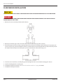
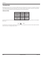
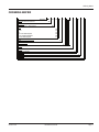
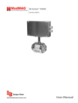
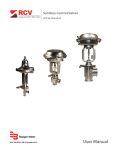
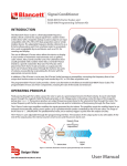
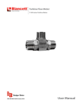
Sensor
Series 735 Plastic Tee Type Flow Sensor
SEN-UM-01665-EN-04 (October 2015)
User Manual
Sensor, Series 735 Plastic Tee Type Flow Sensor
CONTENTS
Scope of This Manual . . . . . . . . . . . . . . . . . . . . . . . . . . . . . . . . . . . . . . . . . . . . . . . . . . . . . . . . . . . . . . . . . . . . 3
Unpacking and Inspection . . . . . . . . . . . . . . . . . . . . . . . . . . . . . . . . . . . . . . . . . . . . . . . . . . . . . . . . . . . . . . . . 3
Safety . . . . . . . . . . . . . . . . . . . . . . . . . . . . . . . . . . . . . . . . . . . . . . . . . . . . . . . . . . . . . . . . . . . . . . . . . . . . . 3
Terminology and Symbols . . . . . . . . . . . . . . . . . . . . . . . . . . . . . . . . . . . . . . . . . . . . . . . . . . . . . . . . . . . . . . 3
Considerations . . . . . . . . . . . . . . . . . . . . . . . . . . . . . . . . . . . . . . . . . . . . . . . . . . . . . . . . . . . . . . . . . . . . . 3
Introduction . . . . . . . . . . . . . . . . . . . . . . . . . . . . . . . . . . . . . . . . . . . . . . . . . . . . . . . . . . . . . . . . . . . . . . . . . 4
Electronic Types . . . . . . . . . . . . . . . . . . . . . . . . . . . . . . . . . . . . . . . . . . . . . . . . . . . . . . . . . . . . . . . . . . . . . . . 4
IR Sensor . . . . . . . . . . . . . . . . . . . . . . . . . . . . . . . . . . . . . . . . . . . . . . . . . . . . . . . . . . . . . . . . . . . . . . . . . 4
Series 735 . . . . . . . . . . . . . . . . . . . . . . . . . . . . . . . . . . . . . . . . . . . . . . . . . . . . . . . . . . . . . . . . . . . . . . . . 4
Mechanical Installation . . . . . . . . . . . . . . . . . . . . . . . . . . . . . . . . . . . . . . . . . . . . . . . . . . . . . . . . . . . . . . . . . . 4
Electrical Installation Guidelines . . . . . . . . . . . . . . . . . . . . . . . . . . . . . . . . . . . . . . . . . . . . . . . . . . . . . . . . . . . . . 5
Flow Sensor Installation . . . . . . . . . . . . . . . . . . . . . . . . . . . . . . . . . . . . . . . . . . . . . . . . . . . . . . . . . . . . . . . . . . 6
Additional Information . . . . . . . . . . . . . . . . . . . . . . . . . . . . . . . . . . . . . . . . . . . . . . . . . . . . . . . . . . . . . . . . 7
Calibration . . . . . . . . . . . . . . . . . . . . . . . . . . . . . . . . . . . . . . . . . . . . . . . . . . . . . . . . . . . . . . . . . . . . . . . . . . 8
Calibration Table . . . . . . . . . . . . . . . . . . . . . . . . . . . . . . . . . . . . . . . . . . . . . . . . . . . . . . . . . . . . . . . . . . . . 8
Dimensions . . . . . . . . . . . . . . . . . . . . . . . . . . . . . . . . . . . . . . . . . . . . . . . . . . . . . . . . . . . . . . . . . . . . . . . . . . 9
Specifications . . . . . . . . . . . . . . . . . . . . . . . . . . . . . . . . . . . . . . . . . . . . . . . . . . . . . . . . . . . . . . . . . . . . . . . . 10
Ordering Matrix . . . . . . . . . . . . . . . . . . . . . . . . . . . . . . . . . . . . . . . . . . . . . . . . . . . . . . . . . . . . . . . . . . . . . . 11
Page ii
SEN-UM-01665-EN-04
October 2015
Scope of This Manual
SCOPE OF THIS MANUAL
This manual is intended to help you get the Series 735 flow sensor up and running quickly.
IIMPORTAN
Read this manual carefully before attempting any installation or operation. Keep the manual accessible for future reference.
UNPACKING AND INSPECTION
Upon opening the shipping container, visually inspect the product and applicable accessories for any physical damage such
as scratches, loose or broken parts, or any other sign of damage that may have occurred during shipment.
NNOTE: If damage is found, request an inspection by the carrier’s agent within 48 hours of delivery and file a claim with the
carrier. A claim for equipment damage in transit is the sole responsibility of the purchaser.
SAFETY
Terminology and Symbols
Indicates a hazardous situation, which, if not avoided, is estimated to be capable of causing death or
serious personal injury.
Indicates a hazardous situation, which, if not avoided, could result in severe personal injury or death.
Indicates a hazardous situation, which, if not avoided, is estimated to be capable of causing minor or
moderate personal injury or damage to property.
Considerations
THE IMPELLER STYLE FLOW SENSOR DESCRIBED IN THIS MANUAL IS NOT INTENDED FOR USE IN SAFETY CRITICAL
APPLICATIONS. USE OF THE DEVICE IN THIS MANNER IS DONE AT THE SOLE DISCRETION OF THE CUSTOMER AND/OR
END USER OF THE DEVICE
THE IMPELLER STYLE FLOW SENSOR DESCRIBED IN THIS MANUAL IS NOT INTENDED FOR USE IN SYSTEMS WITH
FLAMMABLE LIQUIDS OR GASES. ADDITIONALLY, THE DEVICE IS NOT INTENDED FOR SYSTEMS CONTAINING
HAZARDOUS FLUIDS, OR FLUIDS OTHER THAN WATER.
THE IMPELLER STYLE FLOW SENSOR DESCRIBED IN THIS MANUAL MUST BE INSTALLED IN ACCORDANCE WITH ALL
LOCAL AND FEDERAL CODES OR END USE STANDARDS AS APPLICABLE.
IF THE DEVICES DESCRIBED IN THIS MANUAL ARE USED IN A MANNER NOT SPECIFIED BY THE MANUFACTURER, THE
PROTECTION PROVIDED BY THE EQUIPMENT MAY BE IMPAIRED.
IIMPORTAN
Not following instructions properly may impair safety of equipment and/or personnel.
October 2015
SEN-UM-01665-EN-04
Page 3
Introduction
INTRODUCTION
Used in conjunction with any Badger Meter® flow monitor or endpoint, Badger Meter non-magnetic Impeller flow sensors
provide an accurate reading of the rate of liquid flow as well as total accumulated flow. A number of sensor models are
offered, which cover applications for a wide range of pipe sizes and pressure/temperature specifications.
The flow sensors generate a frequency which is proportional to flow rate. An internal preamplifier allows the pulse signal to
travel up to 2000 feet without further amplification. The impeller bearing assembly, shaft and O-rings are replaceable in
the field.
The Series 735 Impeller flow sensors feature a four-blade impeller design, using a proprietary, non-magnetic sensing technology.
As the liquid flow turns the impeller, a low impedance signal is transmitted with a frequency proportional to the flow rate.
Sensors of similar type are interchangeable, so there is no need for recalibration after servicing or replacement.
ELECTRONIC TYPES
Sensors are supplied with two single-conductor 18 AWG solid copper wire leads with UL Style 116666 direct burial insulation.
These IR models are used in below grade applications such as irrigation, municipal and groundwater monitoring. All
Badger Meter Series 735 sensor electrical components are self-contained. See "Specifications" on page 10 for pressure and
temperature ratings.
IR Sensor
Designed for below grade applications such as irrigation, municipal, and groundwater monitoring where the flow rates are
between 2…20 ft/sec. and temperatures are below 110° F. IR sensors are supplied with two single conductor, 18 AWG solid
copper wire with UL Style 116666 direct burial insulation.
Series 735
These models feature a modified PVC tee with solvent weld socket end connections, and a removable PPS sensor insert. Available
sizes are 1/2 in. (12.7 mm), 3/4 in. (19.05 mm) and 1 in. (25.4 mm). BSP threaded adapters are available.
MECHANICAL INSTALLATION
DEPRESSURIZE AND VENT PIPING SYSTEM PRIOR TO ANY INSTALLATION OR MAINTENANCE OF THE FLOW SENSOR.
The accuracy of flow measurement for all flow measuring devices is highly dependent on proper location of the sensor in the
piping system. Irregular flow velocity profiles caused by valves, fittings, and pipe bends can lead to inaccurate overall flow
rate indications, even though local flow velocity measurement may be accurate. A sensor located in the pipe where it can be
affected by air bubbles, floating debris or sediment may not achieve full accuracy and could be damaged. Badger Meter flow
sensors are designed to operate reliably under adverse conditions, but the following recommendations should be followed to
ensure maximum system accuracy:
• Choose a location along the pipe with ten pipe diameters upstream and five pipe diameters downstream of the sensor
provide no flow disturbance. Pipe bends, valves, other fittings, pipe enlargements and reductions should not be present in
this length of pipe.
• The preferred location for the sensor around the circumference of a horizontal pipe is on top. If trapped air or debris will
interfere, then the sensor should be located further around the pipe from the top but not more than 45 degrees from
top dead center. The sensor should never be located at the bottom of the pipe, as sediment may collect there. Locations
off top dead center cause the impeller friction to increase, which may affect performance at low flow rates and increase
wear. Any circumferential location is correct for installation in vertical pipes. Rising flow preferred to reduce effects of any
trapped air.
Page 4
SEN-UM-01665-EN-04
October 2015
Electrical Installation Guidelines
ELECTRICAL INSTALLATION GUIDELINES
DISCONNECT POWER FROM FLOW SENSOR SOURCE AND/OR RECEIVING DEVICE PRIOR TO ANY INSTALLATION OR
MAINTENANCE OF THE SYSTEM.
FLOW SENSOR SOURCE AND/OR RECEIVING DEVICE MUST PROVIDE BASIC ISOLATION FROM MAINS FOR SAFE
OPERATION OF THE SYSTEM.
The sensor leads are supplied with watertight caps over the ends.
• Do not remove the plastic caps from the sensor leads until you are ready to splice.
• Use a twisted pair cable suitable for direct burial to connect the sensor to the endpoint, monitor, or controller. Multi-pair
telecommunication cable or direct burial cables may be used.
• Make a watertight splice using a two-part epoxy type waterproof kit. Be sure the epoxy seals the ends of the cable jacket.
• Make sure the epoxy is hardened before inverting the splice or dropping it in standing water.
• Do not make an underground splice unless absolutely necessary.
• Route the cable from the sensor to a Badger Meter flow monitor or endpoint. The cable may be extended up to 2000 ft,
using two-conductor shielded 20 AWG or larger stranded copper wire with appropriate ratings. Leave enough flexibility in
the cable or conduit to allow for future service.
• When connecting to a Badger Meter flow monitor or endpoint, locate the section of terminal strip on the monitor labeled
SENSOR INPUT or SENSOR. Connect the red wire to IN, SIGNAL(+) or SIGNAL terminal and the black wire to GND, SIGNAL(–)
or COM terminal and the shield drain wire (if applicable) to SLD.
• When interfacing with other equipment, the signal wave forms and power requirements are as shown in "Specifications" on
page 10.
October 2015
SEN-UM-01665-EN-04
Page 5
Flow Sensor Installation
FLOW SENSOR INSTALLATION
DEPRESSURIZE AND VENT PIPING SYSTEM PRIOR TO ANY INSTALLATION OR MAINTENANCE OF THE FLOW SENSOR.
DISCONNECT POWER FROM FLOW SENSOR SOURCE AND/OR RECEIVING DEVICE PRIOR TO ANY INSTALLATION OR
MAINTENANCE OF THE SYSTEM.
1. Remove the sensor assembly and the nut from the tee.
2. Remove burrs from the pipe ends and remove dirt and loose debris from pipe and tee sockets.
3. Glue the line pipe into the tee using an appropriate primer and cement according to the manufacturer's instructions. Do
not use or leave excess glue. Glue build-up in the tee can affect the measurement performance of the unit and/or prevent
the impeller from turning. Do not let the glue or primer contact the bore where the O-rings seal.
4.
5.
6.
7.
Insert the sensor into the tee, carefully lining up the locating hole in the sensor with the locating pin in the tee.
Install and hand-tighten the retaining nut.
Complete the wiring connections. See "Electrical Installation Guidelines" on page 5 for details.
Complete the wiring connections.
Page 6
SEN-UM-01665-EN-04
October 2015
Flow Sensor Installation
Additional Information
• The unit functions best with schedule 40 or a pipe wall thinner than schedule 40.
• Keep all parts as clean as possible. Do not let the glue or primer contact the surfaces where the O-rings make their seal.
• Although the meter can measure at velocities up to 20 ft/sec, do not exceed velocities above 7.5 ft/sec.
October 2015
SEN-UM-01665-EN-04
Page 7
Calibration
CALIBRATION
Badger Meter Impeller sensors use unique K and offset numbers for calibration. These numbers are derived from calibration
runs using NIST traceable instruments. Using both a K and an offset number provides higher accuracy than using a K-factor
alone. The K and offset numbers for each tee configuration are listed in the table below.
Calibration Table
Size/Schedule
K
Offset
1/2" S40
0.078000
0.9
1/2" SDR 13.5
0.120119
0.1
3/4" S40
0.156300
0.9
3/4" SDR 21
0.197000
–0.6
1" S40
0.261119
1.2
1" SDR 21
0.321739
0.6
Input the information in the table above into the following equation to determine the frequency of the Series 735 Impeller
flow sensors:
Freq =
gpm
– offset
K
This information is required when calibrating an output board when using the raw sensor data as direct output to interface
with a device that is not a Badger Meter product.
Page 8
SEN-UM-01665-EN-04
October 2015
Dimensions
DIMENSIONS
October 2015
A
Soc Size, NPS
B
Centerline to Top
L
L BSP Optional
1/2 in. [Ø 0.840"]
3.85 in. (97.8 mm)
3.06 in. (77.7 mm)
6.086 in. (154.6 mm)
3/4 in. [Ø 1.050"]
3.85 in. (97.8 mm)
3.31 in. (84.1 mm)
6.775 in. (172.1 mm)
1 in. [Ø 1.315"]
3.94 in. (100.1 mm)
3.50 in. (88.9 mm)
6.775 in. (172.1 mm)
SEN-UM-01665-EN-04
Page 9
Specifications
SPECIFICATIONS
Wetted Materials (except tees)
Materials
Tee
Adapter
BSP Fitting
Sensor Housing
Retaining Nut
Locating Pin
Impeller
Shaft
Bearing
O-Rings
Wires
See "Ordering Matrix" on page 11 for material specifications
PVC Type 1, white
PVC Type 1, gray
PVC Type 1
PPS
Acetal copolymer, black
300SST
300SST
Tungsten Carbide
UHMWPE
EPDM
18 AWG Irrigation Wire (solid copper)
150 psig @ 73° F (22.8° C)
Pressure/Temperature Ratings
75 psig @ 110° F (43.3° C)
Operating: 35…110° F (1.67…43.3° C)
Rated Temperature
Storage 14…110° F (–10…43.3° C)
Recommended Design Flow
2…20 ft/sec (0.6…6.1 m/sec)
Range
Accuracy
± 3.0% of full scale over recommended design flow range
Repeatability
± 1.5% of full scale over recommended design flow range
Linearity
± 1.5% of full scale over recommended design flow range
8…35V DC max. input, source limited to 100 mA
Quiescent current 600 uA @ 8…35V DC max.
Transducer Excitation
Quiescent voltage (Vhigh=Supply Voltage–(600 uA*Supply impedance))
ON State (Vlow) Max. 1.2V DC @ 40 mA current limit (15 Ω + 0.7V DC)
Output Frequency
3.2…200 Hz
Output Pulse Width
5 msec ±25%
IP 68 / NEMA 4X
Suitable for pollution degree 4 environments
Environmental
Suitable for outdoor use above or below grade
Suitable for use in 100% humidity
Electrical Cable for IR Sensor
UL Style 116666 copper solid AWG 18 wire w/direct burial insulation rated to 105° C
Electronics
Page 10
SEN-UM-01665-EN-04
October 2015
Ordering Matrix
ORDERING MATRIX
STYLE
Tee Mounted Insert Sensor
MATERIAL
PVC (.5", .75", 1" Sch 40 only)
SIZE
0.5"
0.75"
1"
0.5" with BSP Adapters
0.75" with BSP Adapters
1" with BSP Adapters
ELECTRONICS HOUSING
PPS
ELECTRONICS
IR-Irrigation
O-RING
EPDM
SHAFT
Tungsten Carbide
IMPELLER
300 SST
BEARING
UHMWPE
October 2015
Example: 7
35
PV
05
0
6
-
1
2
0
1
35
PV
05
07
10
06
08
11
0
6
1
2
0
1
SEN-UM-01665-EN-04
Page 11
Sensor, Series 735 Plastic Tee Type Flow Sensor
Control. Manage. Optimize.
DATA INDUSTRIAL is a registered trademark of Badger Meter, Inc. Other trademarks appearing in this document are the property of their respective entities. Due to continuous
research, product improvements and enhancements, Badger Meter reserves the right to change product or system specifications without notice, except to the extent an
outstanding contractual obligation exists. © 2015 Badger Meter, Inc. All rights reserved.
www.badgermeter.com
The Americas | Badger Meter | 4545 West Brown Deer Rd | PO Box 245036 | Milwaukee, WI 53224-9536 | 800-876-3837 | 414-355-0400
México | Badger Meter de las Americas, S.A. de C.V. | Pedro Luis Ogazón N°32 | Esq. Angelina N°24 | Colonia Guadalupe Inn | CP 01050 | México, DF | México | +52-55-5662-0882
Europe, Middle East and Africa | Badger Meter Europa GmbH | Nurtinger Str 76 | 72639 Neuffen | Germany | +49-7025-9208-0
Europe, Middle East Branch Office | Badger Meter Europe | PO Box 341442 | Dubai Silicon Oasis, Head Quarter Building, Wing C, Office #C209 | Dubai / UAE | +971-4-371 2503
Czech Republic | Badger Meter Czech Republic s.r.o. | Maříkova 2082/26 | 621 00 Brno, Czech Republic | +420-5-41420411
Slovakia | Badger Meter Slovakia s.r.o. | Racianska 109/B | 831 02 Bratislava, Slovakia | +421-2-44 63 83 01
Asia Pacific | Badger Meter | 80 Marine Parade Rd | 21-06 Parkway Parade | Singapore 449269 | +65-63464836
China | Badger Meter | 7-1202 | 99 Hangzhong Road | Minhang District | Shanghai | China 201101 | +86-21-5763 5412
Legacy Document Number: 880096-0001-EN