1
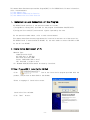
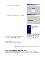
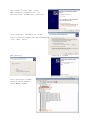
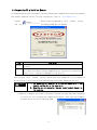
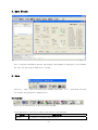
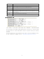
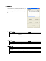
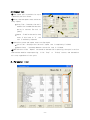
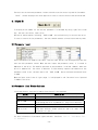
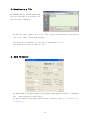
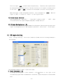
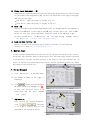
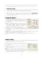
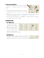
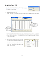
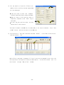
User Manual
User Program(GUI) Function
- Table of Contents -
1. Installation and Connection of the Program ............... 4
1.1 Installation Environment of PC.................................................... 4
1.2 User Program(GUI) Installation Method ............................................. 4
1.3 USB to RS-485 Converter Installation Method ....................................... 5
1.4 Connecting PC with Drive Module................................................... 7
2. Main Window ............................................................ 8
2.1 Menu ............................................................................. 8
2.2 Toolbar .......................................................................... 8
2.3 Cmd(Command) Bar ................................................................. 9
2.4 Board List ...................................................................... 10
2.4.1 Parameter Area ............................................................ 10
2.4.2 I/O Area .................................................................. 10
2.4.3 Motion Area ............................................................... 10
2.5 Repeat Test ..................................................................... 11
3. Parameter List ........................................................ 11
3.1 Slave No ........................................................................ 12
3.2 Parameter Input ................................................................. 12
3.3 Parameter List Window Buttons.................................................... 12
3.4 Save/Load to a File ............................................................. 13
4. Axis Parameter ........................................................ 13
5. I/O Monitoring ........................................................ 14
6. I/O Logic Setting ..................................................... 15
7. Motion Test ........................................................... 16
7.1 Prior Movement .................................................................. 16
-2-
7.2 Single Move Operation ........................................................... 17
7.3 Position Status ................................................................. 17
7.4 Axis Status and Alarm ........................................................... 18
7.5 Stop Operating .................................................................. 18
7.5.1 Temporary Stop ............................................................ 18
7.5.2 Complete Stop ............................................................. 18
8. Position Table (PT) ................................................... 19
-3-
This manual describes how to operate User Program(GUI) for Ezi-SERVO Pus-R. For more information,
refer related manuals.
(1) User Manual-Text
(2) User Manual-Communication Function
(3) User Manual-Position Table Function
1. Installation and Connection of the Program
Ezi-SERVO Plus-R consists of two operation modes as follows:
1) Using Motion Library(DLL) provided for the program from Windows 2000/XP/VISTA
2) Using position table(PT) and external signals inputted by the user
For the operation modes above, refer to each related manual.
This chapter describes the user program used for installation and test run of the controller.
Ezi-SERVO Plus-R is associated with RS-485. So, the user needs to convert RS-232C or USB
for the PC into RS-485
1.1 Installation Environment of PC
Machine Type :
Compatible with PC/AT
RS-232C Port or USB Port
Hard disk more than 10MB
Screen SVGA(1024×768 or more)
CPU Pentium4 2.0 GHz or more
OS: Windows 2000/XP/VISTA should be normally installed.
1.2 User Program(GUI) Installation Method
Click
icon at the installation program provided with the
product, and perform as described at the window.
Select a language of installation screen.
Installation Start window.
Click ‘Next’ button.
-4-
Select all installation components,
and click ‘next’ button.
Select a folder which the program is installed,
and click ‘Install’ button.
Installation is finished.
Then installation is finished at the selected folder,
‘Program Files/FASTECH/EziMOTION PlusR’
folder is created and also GUI icon and program
folders are installed.
1)Include folder : *dll, *.lib, *.h files
2)Example folder : source code for sample
3)PT_Samples folder : sample data files for position table.
4)FTDI USB Driver folder : driver program for USB converter
When using USB to RS-485 converter, you need to install driver
program for that.
1.3 USB to RS-485 Converter Installation Method
In case of using RS-232 to RS-485 converter, there’s no need to install for converter.
But when you connecting USB to RS-485 converter to PC, you can see the Installation Start window.
-5-
After select ① click ‘Next’ button.
When internet is connected to PC, it is
possible to use ‘automatically’installation
①
After select the ‘FTDI USB Driver’folder
(that is installed together with User Program(GUI),
click ‘Next’ button.
Now installing.
Installing is finished.
After installation finished,
converter can be checked in
Device Manager window.
-6-
1.4 Connecting PC with Drive Module
To communicate with controller module, the user should prepare communication converter and cable
and connect them with the PC. For more information, refer to 「User Manual-Text」.
Execute
which is User Program(GUI), click ‘Connect’ button,
and
following window will be opened.
the
Item
Description
Port No.
To assign the port number of RS-232 or USB which is connected with drive module
at the PC
Baudrate
To measure the communication speed that connects the drive to RS-485 communication.
This should correspond to the switch(SW2) which sets the controller communication
speed. (Drive : adjusted to 115200[bps] at the factory).
After setting, click ‘Connect’ button, and the controller module will try to connect 16
drives from 0 to 15 at the setting speed through a pertinent communication port.
Caution
1. The communication speed of drive modules connected with one
segment must be set to the same value.
2. When they are not connected, the user needs to check the port or
the baudrate.
(2) When drive modules are normally connected, the user can check detailed information
of controller list including the communication speed , motor type and Firmware
program version at the following window.
-7-
2. Main Window
This is the basic window to operate the program. Each window is displayed in this window.
The user can open each window with a toolbar.
2.1 Menu
There are ‘View’ menu to display other windows simply and ‘File’ menu which the user
can connect and disconnect communication.
2.2 Toolbar
There are various buttons to go to the next window.
Click each button, and the following functions will be executed.
Button
Connect
Description
To connect or disconnect with the drive
-8-
Board List
To display connected module information and communication status
Parameter list
To set parameter values related to operation control like a position command
Axis Param
To sort parameters that the user can change them easily
I/O Monitor
To monitor digital I/O signals of CN1 connector
I/O Setting
To set digital I/O signal assignment of CN1 connector
To execute motion commands such as Jog operation, Position operation, Origin
Motion Test
return operation
Pos Table
To input and execute position table data
Cmd Bar
To display DLL function corresponding to the command being executed
2.3 Cmd(Command) Bar
Click ‘Cmd Bar’ at the toolbar or check ‘Menu –View – Command Bar’, and the above window
will be displayed. This window includes commands used for the controller. The use can check
that which function is used, how parameter values are inputted, and they are normally
processed.
The above window displays functions which the user inputs or functions used when he clicks.
For more information of commands, refer to 「User Manual-Communication Function」.
-9-
2.4 Board List
To check the drive list connected with communication.
The user can check information of each drive. There
are buttons to go to windows for function setting or
test.
2.4.1 Parameter Area
Button
Function
To display the window that the user can check, edit, and manage drive
Parameter List
parameters
Axis Parameter
To display parameters edited when the machine is set up
2.4.2 I/O Area
Button
Function
I/O Monitor
To monitor digital I/O signals of CN1 connector
I/O Setting
To set digital I/O signal assignment of CN1 connector.
2.4.3 Motion Area
Button
Function
To execute motion commands such as Jog operation, Position
Motion Test
operation, Origin return operation
Repeat Test
To test fixed motioning for 1 axis repeatedly
Position Table
To input and execute position table data
- 10 -
2.5 Repeat Test
① The repeat test is possible for up to
①
3 absolute position values.
③
② Delay time and repeat count can be set
every repeat.
* Delay Time : Stand-by time until
each motion is ended and then next
②
motion is started. The unit is
④
[msec].
* Repeat : To define the motion loop
count. If this is set to ‘0’, the
test is endlessly repeated.
③ Operation status and repeat count are displayed.
* Cycle Time : displays the time until repeat test is completely finished.
* Repeat Count : increases whenever one motion loop is finished.
④ When the user clicks ‘Repeat’ button while the machine is operating, the cycle in service
ends and the machine stops operating. Click ‘Stop’ or ‘E-Stop’ button, and the machine
will stop regardless of the cycle.
3. Parameter List
- 11 -
The user can set and save parameter values related to motion control by each drive module.
‘Value’ column displays the value applied to control current motion and can be edited.
3.1 Slave No
To display drive number for the current parameter list window. By using right/left arrow
key, the user can select other drive.
Buttons at the bottom bar including ‘SAVE to ROM’ are available only for the current drive.
To control several drive parameters, the user should execute related slave each by each.
3.2 Parameter Input
Select parameters as shown at the table, and the input box will be displayed and then the
user can edit parameter values. When the user inputs the parameter value, it is saved to
RAM area of the drive. The machine operates as the parameter is edited. However, when the
drive is powered off, the value is deleted. To continuously operate the machine as the
parameter value is set, the user must click ‘SAVE to ROM’ button and save the edited value
to ROM.
When the input value is out of right range, it is displayed in red. The value is not inputted
in RAM of the drive.
3.3 Parameter List Window Buttons
Click each button, and the following functions will be executed.
Button
SET to DEFAULT
LOAD ROM
SAVE to ROM
LOAD FILE
SAVE to FILE
Description
Converts all parameter values into ‘Default Value’.
Converts ‘Value’ items into values saved to the ROM area.
Saves ‘Value’ items to the ROM area.
(Even though the drive is powered off, they are not deleted.)
Sets ‘Value’ items to the values saved to an external file.
Saves the current values to an external file.
(The user defines folder position and file name. The
extension is *.fpt.)
For more information of parameter types and their functions, refer to 「User Manual–Text,
12. Parameters」.
- 12 -
3.4 Save/Load to a File
Ezi-SERVO PlusR can save parameters and
position table data to an external file
and read them if necessary.
The user can input a name of file, click ‘Save’ button, and save data. He can select a
file, click ‘Open’ button and read data.
File extension for parameter is *.fpt and for Input/output is *.fit.
File extension for position table is *.txt.
4. Axis Parameter
The above window is to enable the user to easily operate some important items of ‘3. Parameter
List’ items according to each function.
For more information of parameter types and their functions, refer to 「User Manual–Text,
12. Parameters」.
- 13 -
5. I/O Monitoring
The user can set and check control I/O signals related to operation control through CN1
connecter. The next window is the sample setting of I/O Monitoring status.
②
①
③
④
1) Input Signal : ①
There are 32 definable input signals. However, just 12 signals of them can be connected
with CN1 connecter physically at one time.
The first three signals are fixed to ‘LIMIT+ ’, ‘LIMIT- ’and ‘ORIGIN ’sensors.
Therefore other signals cannot be connected and used with these pins. The user can set
up to 9 signals to Input 9 pins at one time. ‘IN1 ’~‘IN9 ’indicators are displayed
to current setting signals.
When each signal is [ON] through CN1 connecter, icon is changed into ‘green’. When the
signal is [OFF], it returns to ‘white’ to the original state.
2) Virtual Input Function : ②
Even though the input pin is not assigned to ‘IN1’~‘IN9’ at all, the user can click
each button and virtually change the signal into [ON]/[OFF]. For instance, click ‘Pause’
button, and the temporary stop function will be operated. But ‘PT Start’ signal is
exceptional.
3) Output Signal : ③
There are 24 definable output signals. However, just 10 signals of them can be connected
with CN1 connecter physically at one time
- 14 -
The first signal ‘COMP’ is used to specific purpose only. Therefore other signals cannot
be connected and used with this pin. The user can set up to 9 signals to Output 9 pins
at one time. ‘OUT1’~‘OUT9’ indicators are displayed to current setting signals.
When each signal is [ON] through CN1 connecter, icon is changed into ‘green’. When the
signal is [OFF], it returns to ‘white’ to the original state.
4) Virtual Output Function:
After assigning the ‘User OUT 0’ ~ ‘User OUT 8’signals to OUT1’ ~ ‘OUT9’, when
click that button the signal changed [ON]/[OFF] through that pin.
5) I/O Logic Setting button : ④
Click this icon, and the following window will be displayed. Then he can assign a pertinent
signal to the physical pin of CN1 connecter and define ‘Active Level’ of the signal.
6. I/O Logic Setting
Click ‘I/O Logic Setting’ icon at the I/O Monitor window, and the following window will
be displayed.
②
①
③
④
The assignment method is same in input and output.
1) Signal Assignment : ①
To change pin assignment of CN1 connecter, click
button to the right of the
corresponding signal name as showed above, and select signals displayed to the drop-down
menu.
- 15 -
2) Signal Level Assignment : ②
These buttons provide the user with functions that he can select the active level of signal
for the signal to be recognized to [ON]. He can click the button to the right of the signal
name and set the signal.
* Low Active : when the signal is set[ON] to 0 volt
* High Active : when the signal is set[ON] to 24 volt
3) Save : ③
Output pin of CN1 can be set described same as input. All changed matters are temporarily
saved to the RAM area. To save them to the ROM area, the user must click ‘Save to ROM’
button. At this time, current parameter values are saved to the ROM area as well.
For more information of ‘I/O Monitoring’ and ‘I/O Logic Setting’ windows, refer to
「User Manual-Text, 7. Control Input and Output Signal」.
4) Load and Save to File : ④
Current I/O Logic setting status can be saved to external file and load from
External file. Refer to 「3.4 Save/Read toa File」.
7. Motion Test
To test the motor connected with the controller drive. The user can test motion for one axis.
He can test that the motor moves to the given position, and also simply transfer the motor
to one direction. The user can move the motor to the origin or the limit and then test its
sensor. At the position status and the axis status, the user can check the position, speed,
①
and status of the current axis.
7.1 Prior Movement
1) Click ‘Motion Test’ at the manin menu.
2) The window as shown to the right is
③
displayed.
3) Click
, and the motor will be Servo
ON and the icon will be changed into
.
At this time, the motor starts to be
electrified
and
the
motor
becomes
⑤
‘lock’ status.
4) Jog Operation
After setting jog related parameters,
click
and press
it for a while, and the motor will be
operated to the setting direction.
- 16 -
⑦
④
⑥
5) According to the motion of motor, the user can check its position and operation status.
For more information, refer to 「User Manual-Text, 9. Other Operation Functions」.
6) Origin Return Operation.
Click ‘Origin’, and origin return motion will be operated. The motion type may be
different subject to how origin return type(parameter) is selected.
7) When origin return is finished, the red LED is displayed to ON like
at the ‘Axis Status’ window. For more information, refer to 「User Manual-Text, 9.
Other Operation Functions」.
7.2 Single Move Operation
The user can test straight-line move command for one axis.
‘Abs Move’ button finds and moves to the absolute position,
and ‘DEC Move’ and ‘INC Move’ find and move to the
relative position.
* Cmd Pos : Indicates target position value. The unit is
[pulse]. When ‘Abs Move’ is executed, this displays the
absolute position. When ‘DEC Move’ or ‘INC Move’ is
executed, this displays the relative position.
* Start Speed : To set AxisStartSpeed at the second item
in parameter lists.‘Start Speed’ should be smaller than
‘Move Speed’.
* Move Speed : To set the moving speed when Abs Move, DEC Move, or INC Move is executed. ‘Move
Speed’ should be larger than ‘Start Speed’.
* Accel Time, Decel Time : To set AxisAccel and AxisDecelTime in parameter lists.
7.3 Position Status
To displays the current position of axis. Click Clear Position button, and Cmd Pos value and
Actual Pos value will be initialized to ‘0(zero)’.
* Cmd Pos : displays target position value while the motor
is operating.
* Actual Pos : displays current position value while the
motor is operating.
* Actual Vel : displays the actual operation speed of motor.
* Pos Error : displays the difference between Cmd Pos value
and Actual Pos value. By this value, the user can check
how much the current target position is tracked.
- 17 -
7.4 Axis Status and Alarm
②
To display the current axis status. Each status is displayed
to On/Off. ‘On’ indicates in red and ‘Off’ indicates in
①
white.
1) When the motor stops operating and Inposition is finished,
③
the corresponding LED at the right figure is displayed
in red.
2) When an alarm occurs during operation, the corresponding LED is displayed in red. For more
information of alarm types, refer to 「User Manual-Text, 7.4 Output Signal」.
3) After removing the alarm cause, click ‘ALARM RESET’ to check that the alarm is released.
Then change the LED into Servo ON again.
7.5 Stop Operating
7.5.1 Temporary Stop
Click ‘Pause’ button at the
I/O
Monitoring
window
to
temporarily stop the motion.
When clicking the button again,
the motor restarts to operate.
If ‘Pause’ signal is set to
IN1~IN9, the actual external
signal must be supplied to [ON] status.
7.5.2 Complete Stop
When the motor needs to stop during operation, the button
as shown to the right is available. ‘STOP’ button includes
deceleration function, while ‘E-STOP’ button does not include deceleration function.
- 18 -
8. Position Table (PT)
For more information of position table, refer to 「User
Manual-Position
Table
Function」.
This
chapter
introduces its basic usage.
1) Reading position table data
Click ‘Pos Table’ icon at the main menu, and data saved to the RAM area will be loaded
and then the following window will be displayed.
Select drive
no.
Scroll this bar up and
down to display up
to 256 PT data.
Scroll this bar
right and left to
display setting
items.
Position table data can be changed at any time. The position table can save up to 256 step
data. If the position table is used to the program area, it may be used for all point numbers
without restriction. That is, it is possible to start at a random point number and jump
to other point number.
2) Put the mouse on a specific PT data line, click
its right button, and the pop-up menu will be
displayed as shown to the right. All of the
functions can be implemented. Click ‘Edit
Item’, and the user can edit data at the
window like 3) below.
- 19 -
②
3) Put the mouse on a specific PT data line,
③-1
double click its left key, and the right window
will be displayed.
* Input the value in order from ‘Command’
related items according to operation modes.
* When all data of the positing table is
completely inputted, click ‘Save’ key to
save data.
③-3
③-2
* To edit the next position table, the user
should use PT select button.
This data is saved to the RAM area. So, when power is off, data is deleted. Click ‘Save
to ROM’ button, and save the data to the ROM area.
4) Set the motor to ‘Servo ON’and select the mode ‘Normal’, click PT No to start motion,
and then execute ‘Run’.
④-2
④-1
While PT No is operated in sequence, PT lines in service are changed in grey. Also, the
user may monitor the operation status as described at ‘7.3 Position Status’ and ‘7.4
Axis Status’ through ‘Motion Test’ window,
- 20 -
ⓒ
Copyright 2008 FASTECH Co.,Ltd.
All Rights Reserved. Aug 05, 2009 rev.05.01.03
- 21 -