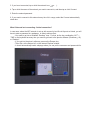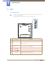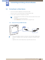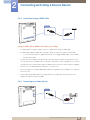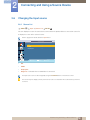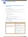
1
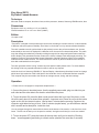
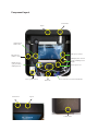
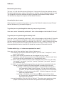
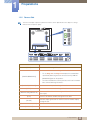
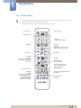
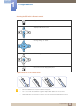
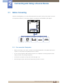
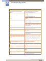
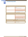
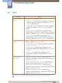
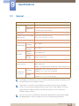
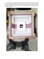
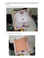
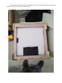
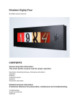
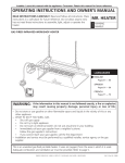
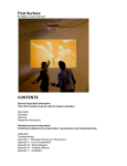
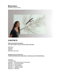
Zero Noon By Rafael Lozano-Hemmer CONTENTS General important information This short section must be read for proper operation Description Operation Component layout Cleaning Placement Instructions Detailed technical information A technical reference for preservation, maintenance and troubleshooting Hardware Software Troubleshooting Support (contact us) Appendix I - Samsung User manual Appendix II - How to crate the artwork General important information Zero Noon (2013) By Rafael Lozano-Hemmer Technique Microsoft Surface computer, aluminum frame, arduino processor, buttons, Samsung UD22B monitor, fans. Dimensions Equipment: 44.5 cm x 44.5cm x 11.5 cm (HxWxD) Crate dimensions: 67 cm x 67 cm x 36cm (LxWxH) Edition 12 copies +2AP Description “Zero Noon” is a digital clock that shows the current time according to eccentric metrics: it uses hundreds of different reference systems. Basically, Zero Noon is a clock that is run by internet-refreshed statistics. The clock’s statistics are all synchronized so that precisely at noon they all zero and start over. At noon automatically a new metric is displayed in a different colour chosen from a determined palette. The public may also change the statistics by manually scrolling through the list using small push-buttons under the built-in display. This guarantees that the content of the clocks is always fresh and thought-provoking. The statistics come from government data, Harper’s Magazine, financial institutions, NGOs, from academic studies and other trusted sources. The actual metrics are chosen by the artist studio but the collector is also able to add statistics to the system. The clock generates a faint “ticking” sound every time that the handle passes noon. For some statistics this ticking will be very sporadic whereas for others it will be very frequent. Inside the clock is a Samsung UD22B 21.5” Square Display, a brand-new professional screen for signage, which has a high resolution of 960 x 960 pixels. Also inside the clock is an Microsoft Surface computer. This computer may be connected to the Internet to manage content, timing, and other settings. Operation ** Please refer to next pages for components emplacement. ** 1.Connect the piece to electrical power. Use the supplied power cable, plug one side into your wall outlet and the other side to the electric outlet behind the piece. 2. To turn the piece ON, press the black round power button that is on top of the piece, on the left, all the way down for a second then release it. Important note: Please do not push the button again as this will shut down the piece. Wait at least 2 minutes before pressing it again as the computer might take that long to boot. After 2 minutes (maybe faster), you should see a statistic with a number and a description, inside the clock. You can navigate through the stats with both buttons at the bottom of the monitor, on the front face of the frame. The left one will lead you to the previous statistic, the right one will lead you to the next statistic. 3. To turn the piece OFF, press the button all the way down until you’ve seen the “Shutting down..” screen appearing and fading to a black screen (shouldn’t be more than 2 seconds). 4. If the piece doesn’t start within 30 seconds, try to turn on the piece again. If it’s still doesn’t turn on, then hold the power button all the way down for 10 seconds. Then, wait at least 3 seconds then press the power button all the way down for 1 second and you should be up and running again. Component layout Power button Top fan USB Connector (tablet’s side) Tablet power connector USB Connector (Arduino’s side) miniDisplay Port connector (going to HDMI port of the display) HDMI connector (going into tablet’s miniDisplay Port) Monitor power cord Piece’s power connector Power button Bottom fan Power connections (for monitor and tablet PC) Top fan Control buttons Cleaning Please do not clean the display surface with Windex or soap. Use a lint-free cloth and LCD screen liquid cleaner, such as Kensington Screen Guardian found in computer stores. Placement Instructions The middle of the frame should be hung at about 150 cm (59 inches) from the ground, which means the top will be at 172.25 cm (67 13/16 inches) from the ground. In order to achieve this, the top of the bracket should be at 169.7 cm (66 13/16 inches) from the ground. Before putting the frame on the wall, ensure the power cord is plugged to the piece and make the frame sits on the wall bracket, while having the frame offset on the left side of the bracket. Then slide the frame gently on the right. Avoid to hit the power button mechanism as it may damage the button functionality. ** Take note that some versions will have a spacing of 1.2 cm (1/2 inch) between the wall and the piece. ** 169.7 cm Detailed technical information Software Bluetooth keyboard keys The keys 1 to 9 will adjust the volume of the piece: 1 being muted, 9 being the maximum volume. The left and right keys are a replica of the buttons on the piece and will navigate through the stats. The Escape key will quit the software and get the computer into Windows Desktop interface. The Windows key will get the computer into the MetroUI interface. Accessing the piece’s menu When the piece is up and running, press on any key of the Bluetooth keyboard (except “Escape” and the “Windows key”): the menu will pop-up. To get the piece to cycle though the stats only once per day (at noon) In the menu, under “Automatically switch stats”, click on the rectangle on the left side of “At noon”. To get the piece to cycle through the stats by itself In the menu, under “Automatically switch stats”, click on the rectangle on the left side of “At regular intervals”. Two components will appear: a slider ans a dropdown list. By clicking on the slider, you can change the numeric value of your intervals - from 0 to 120 -, while by clicking on the drop down list, you can decide if the intervals will be calculated in seconds, minutes or hours. The recommended default values should be 30 minutes for a museum, 30 seconds for a fair. To add a statistic (e.g.: x “crimes were reported since noon”) In the menu, in the “User statistics” panel, click on “Add new one”: - at the bottom of the screen, textboxes will appear, you’ll see “Stat”, “Description”, “Value”, and a “Color” section. - as “Stats”, enter the term you want to see in the biggest font (e.g. crimes); - as “Description”, enter the term you want to see in the smallest font. Ensure to add “since noon” at the end of your description (e.g. “reported since noon”); - as “Value”, enter the number of units you want to add per portion of time. You can select “per second”, “per minute”, “per hour”, “per day”, “per week”, “per month”, “per year” (e.g. 400000 per year); - for “Color”, you can select the background color you want to have associated to the stat. For that, you have 2 options, using the artist palette or creating your own color: - by clicking on “Get color from artist palette”, the system will randomly pick a color selected by Rafael Lozano-Hemmer. You can click as many times you want. The color selected is displayed in a square next to the buttons; - by clicking on “Use the custom color picker”, 3 sliders will appear on the right side of the coloured square; - by clicking on the sliders, you will change the red, green and blue values of your new color. the created color is displayed in the square in between the buttons and the sliders; - to accept the addition of the stat, click on “Add stat”. The system may experience a delay (couple of seconds) which will look like if the system froze while updating itself; - if you don’t want to add the stat anymore, click on “Cancel” and the information you entered won’t be added to the piece. To modify a “User statistic” (e.g.: change “criems were reported since noon” to “crimes were reported since noon”) In the menu, next to your statistic, click on the “Modify” button (e.g. next to the “criems” statistic); - at the bottom of the screen, textboxes will appear, you’ll see “Stat”, “Description”, “Value”, and a “Color” section. - in “Stats”, change “criems” to “crimes”; - you can also change the values entered as “Description, “Value” and “Color”; - to accept the modification of the stat, click on “Confirm”. - if you don’t want to modify the statistic anymore, click on “Cancel” and the information you modified won’t be saved to the piece. The system may experience a delay (couple of seconds) which will look like if it froze while updating itself: just wait 5-10 seconds and the menu will be back within it’s refresh state. To delete a “User statistic” (e.g.: remove “crimes were reported since noon”) In the menu, next to your statistic, click on the “Modify” button (e.g. next to the “crimes” statistic); - at the bottom of the screen, textboxes will appear, you’ll see “Stat”, “Description”, “Value”, and a “Color” section. - to delete the statistic, click on “Delete”. The system may experience a delay (couple of seconds) which will look like if it froze while updating itself: just wait 5-10 seconds and the menu will be back within it’s refresh state. Hardware Bluetooth keyboard A Bluetooth keyboard has been paired with the computer used with the artwork. To operate the piece with it, ensure you can control the computer with it. If the keyboard doesn’t react, ensure the ON/OFF switch is turned to ON. Press on the spacebar key and wait 3 seconds. Press on the spacebar again and the piece should react. If not, replace the batteries. WiFi connection 1. Swipe in from the right edge of the screen, and then tap Settings. (If you’re using a mouse or a trackpad, point to the lower-right corner of the screen, move the mouse pointer up, and then click Settings.) 2. Check the network icon. It’ll show if you’re connected and how strong the connection is. 3. If you’re not connected, tap or click the network icon ( or ). 4. Tap or click the name of the network you want to connect to, and then tap or click Connect. 5. Enter the network password. 6. If you want to connect to this network every time it’s in range, select the Connect automatically check box. What if Internet isn’t connecting - limited connection? In rare case, where the WiFi network is set-up with a security level like in Airports or Hotels, you will have to enter a password in a webpage. In orde to achieve that: - You need to get into a Windows “Desktop” view. For that, do the key combination “ALT” + “TAB” on the keyboard as many time you need to get back to the piece’s software (ZeroNoon_v16) or “Desktop”. - If you get into the piece’s software, press on the Escape key. - Then click, at the bottom left, on the Internet Explorer window. - It should automatically load a webpage where you can put the username and password info. Troubleshooting After pressing the button, nothing seems to happen. Do you hear any sound coming from the frame? If so, the computer is running and the monitor should display the piece shortly. If not, try to press the power button again, if nothing happens; check the power cables connections (frame, monitor and tablet computer). If the piece run but the monitor is still not displaying it, remove the piece from the wall, be careful as the power cord will still be plugged to the frame, and place it on any horizontal surface, facing down. Ensure that the powercords of the monitor and the frame are well connected, then ensure that the miniDisplayPort connector is still in place. Test the piece on that surface before putting it back on the wall. There is an image, but the piece isn’t displayed. Try to restart the piece by pressing the power button once, wait until the screen has been blacked out for 10 seconds and press on the power button again. The piece should show up within 2 minutes. If it’s still not the case, remove the piece from the wall, be careful as the power cord will still be plugged to the frame, and place it on any horizontal surface, facing down. Ensure the USB cable is well connected to the tablet and the Arduino box. Test the piece on that surface before putting it back on the wall. The piece doesn’t react when pressing the front buttons. Remove the piece from the wall, be careful as the power cord will still be plugged to the frame, and place it on any horizontal surface, facing down. Ensure the USB cable is well connected to the tablet and the Arduino box. Test the piece on that surface before putting it back on the wall. Support If you would like support for the piece please feel free to call Lozano-Hemmer’s studio in Canada: Antimodular Research 4060 St-Laurent, studio 107 Montréal Québec H2W 1Y9 Canada Tel 1-514-597-0917 Fax 1-514-597-2092 [email protected] www.antimodular.com Appendix I - Samsung User manual User Manual UD22B The color and the appearance may differ depending on the product, and the specifications are subject to change without prior notice to improve the performance. BN46-00286A-02 1 1.2 Preparations Parts 1.2.1 External sensor The color and shape of parts may differ from what is shown. Specifications are subject to change without notice to improve quality. Keep the area between the remote sensor and remote control obstacle-free. 1 2 3 4 5 Sensor Description Aim the remote control towards this spot on the LCD Display. 1 Remote-control sensor Keep the area between the remote sensor and remote control obstacle-free. 2 Brightness sensor Automatically detects the intensity of ambient light around a selected display and adjusts the screen brightness. 3 Power indicator Turns off in power-on mode and blinks green in power-saving mode. 4 5 [POWER] [SOURCE] Use this button for turning the Display on and off. Switches from PC mode to Video mode. Selects the input source that an external device is connected to. 1 Preparations 21 1.2.2 Reverse Side The color and shape of parts may differ from what is shown. Specifications are subject to change IR OUT IR / AMBIENT SENSOR IN AUDIO OUT without notice to improve quality. RJ45 1 Preparations DP IN HDMI IN (MAGICINFO) DVI OUT (LOOPOUT) Port [DP IN] DVI IN RS232C OUT RS232C IN POWER S/W POWER IN Description Connects to a PC using a DP cable. Connects to a source device using an HDMI cable. To use MagicInfo, the MagicInfo output of the network box specified by Samsung must be connected to the [HDMI IN [HDMI IN (MAGICINFO)] (MAGICINFO)] port on the product. For more information on how to purchase and install a network box, contact Samsung Electronics. [DVI OUT (LOOPOUT)] [DVI IN] [RS232C OUT] [RS232C IN] [RJ45] [IR OUT] [IR / AMBIENT SENSOR IN] [AUDIO OUT] Connects to another product using a DVI cable. Connects to a source device using a DVI cable or HDMI-DVI cable. Connects to RS232C or MDC through an RS232C Serial cable (cross type) Connects to RS232C or MDC through an RJ45 cable Transmits input signals from an external sensor to another display through IR OUT Connects to an external sensor Connects to the audio of a source device. 1 Preparations 23 1 Preparations 1.2.3 Remote Control Using other display devices in the same space as the remote control of this product can cause the other display devices to be inadvertently controlled. Remote control button functions may differ for different products. Power on the product. Power off the product. Change the input source. Number buttons Enter the password in the OSD menu. Not available. Not available. Mute the sound. Unmuting the sound: Press MUTE again or press the volume control(+ VOL -) button. Adjust the volume. Not available. Not available. Not available. Display or hide the onscreen display menu, or return to the previous menu. Not available. Not available. Display information about the current input source. Move to the upper, lower, left or right menu, or adjust an option's setting. Confirm a menu selection. Return to the previous menu. Not available. Not available. MagicInfo Quick Launch Button. This button is disabled for produacts that do not support MagicInfo. MagicInfo can only be enabled when a network box is connected. Exit the current menu. Manually select a connected input source from DVI, HDMI, or DP. It sets safe lock function. Not available. 1 Preparations 25 1 Preparations Adjusting the OSD with the Remote Control 1. Open the OSD menu. 2. Select from Input, Picture, Sound, Setup or Multi Control in the displayed OSD menu screen. 3. Change settings as desired. 4. Finish setting. 5. Close the onscreen display (OSD) menu. To place batteries in the remote control 1 2 3 Store used batteries out of reach of children and recycle. Do not use a new and used battery together. Replace both batteries at the same time. Remove batteries when the remote control is not to be used for an extended period of time. 1 Preparations 26 2 2.1 Connecting and Using a Source Device Before Connecting Check the following before you connect this product with other devices. Devices that can be connected to this product include PCs, camcorders, speakers, set top boxes and DVD/Blu-ray Disc players. Audio 2.1.1 Pre-connection Checkpoints Before connecting a source device, read the user manual provided with it. The number and locations of ports on source devices may differ from device to device. Do not connect the power cable until all connections are completed. Connecting the power cable during connection may damage the product. Connect the sound ports correctly: left = white and right = red. Check the types of ports at the back of the product you want to connect. 2 Connecting and Using a Source Device 45 2 2.4 Connecting and Using a Source Device Connecting to a Video Device Do not connect the power cable before connecting all other cables. Ensure you connect a source device first before connecting the power cable. You can connect a video device to the product using a cable. The following images are for reference only. Real-life situations may differ from what is shown in the images. Connecting parts may differ in different products. Press the SOURCE button on the remote control to change the source. 2.4.1 Connection Using an HDMI-DVI Cable HDMI IN (MAGICINFO) Audio will not be enabled if the product is connected to a video device using an HDMI-DVI cable. To resolve this, additionally connect an audio cable to the audio ports on the product and video device. Supported resolutions include 1080p (50/60Hz), 720p (50/60Hz), 480p, and 576p. 2 Connecting and Using a Source Device 51 2 Connecting and Using a Source Device 2.4.2 Connection Using an HDMI Cable HDMI IN (MAGICINFO) Using an HDMI cable or HDMI to DVI Cable (up to 1080p) For better picture and audio quality, connect to a digital device using an HDMI cable. An HDMI cable supports digital video and audio signals, and does not require an audio cable. To connect the product to a digital device that does not support HDMI output, use an HDMI/ DVI and audio cables. The picture may not display normally (if at all) or the audio may not work if an external device that uses an older version of HDMI mode is connected to the product. If such a problem occurs, ask the manufacturer of the external device about the HDMI version and, if out of date, request an upgrade. Be sure to use an HDMI cable with a thickness of 14 mm or less. Be sure to purchase a certified HDMI cable. Otherwise, the picture may not display or a connection error may occur. A basic high-speed HDMI cable or one with ethernet is recommended. This product does not support the ethernet function via HDMI. 2.4.3 Connecting to an Audio System AUDIO OUT 2 Connecting and Using a Source Device 52 2 2.6 Connecting and Using a Source Device Changing the Input source 2.6.1 Source List O MENU m Input Source List ENTER You can display the screen of a source device connected to the product. Select a source from source list to display the screen of the selected source. Refer to page 89 for details about the Input menu. 6RXUFH/LVW '9, +'0, 'LVSOD\3RUW 0RYH ヲ ヲ ヲ (QWHU 5HWXUQ DVI HDMI DisplayPort MagicInfo - Activated when a network box is connected. The input source can also be changed by using the SOURCE button on the remote control. The screen may not display correctly if an incorrect source is selected for the source device you want to convert to. 2 Connecting and Using a Source Device 54 8 8.1 Troubleshooting Guide Requirements Before Contacting Samsung Customer Service Center 8.1.1 Testing the Product Before calling Samsung Customer Service Center, test your product as follows. If the problem persists, contact Samsung Customer Service Center. Check if your product is operating normally by using the product test function. If the screen remains blank while the power LED blinks even when the product is correctly connected to a PC, perform product testing. 1 2 3 4 Power off both the PC and product. Disconnect all the cables from the product. Power on the product. If "No Signal" is displayed, the product is operating normally. If the screen remains blank, check the PC system, video controller and cable. 8.1.2 Checking the Resolution and Frequency "Not Optimum Mode" will briefly be displayed if a mode that exceeds a supported resolution is selected (refer to Supported Resolutions). 8.1.3 Check the followings. Installation issue The screen keeps switching on and off. Check the cable connection between the product and PC, and ensure the connection is secure. ("2.2 Connecting and Using a PC") Blank spaces are found on all four sides of the screen when an HDMI or HDMI-DVI cable is connected to the product and PC. The blank spaces found on the screen have nothing to do with the product. Blank spaces on the screen are caused by the PC or graphics card. To resolve the problem, adjust the screen size in the HDMI or DVI settings for the graphics card. If the graphics card settings menu does not have an option to adjust the screen size, update the graphics card driver to the latest version. (Please contact the graphics card or computer manufacturer for further details about how to adjust the screen settings.) 8 Troubleshooting Guide 124 8 Troubleshooting Guide Screen issue The power LED is off. The screen will not switch on. Make sure that the power cord is connected. "No Signal" is displayed on the screen (refer to "Connecting to a PC"). Check that the product is connected correctly with a cable ("2.2 Connecting and Using a PC") ("2.2 Connecting and Using a PC") Check that the device connected to the product is powered on. "Not Optimum Mode" is displayed. This message is displayed when a signal from the graphics card exceeds the product's maximum resolution and frequency. Refer to the Standard Signal Mode Table and set the maximum resolution and frequency according to the product specifications. The images on the screen look distorted. Check the cable connection to the product ("2.2 Connecting and Using a PC") The screen is not clear. The screen is blurry. Remove any accessories (video extension cable, etc) and try again. Set the resolution and frequency to the recommended level. The screen appears unstable and shaky. There are shadows or ghost images left on the screen. Check that the resolution and frequency of the PC and graphics card are set within a range compatible with the product. Then, change the screen settings if required by referring to the Additional Information on the product menu and the Standard Signal Mode Table. The screen is too bright. The screen is too dark. Adjust Brightness and Contrast. Screen color is inconsistent. Go to Picture and adjust the Colo(u)r Temp. settings. The colors on the screen have a shadow and are distorted. Go to Picture and adjust the Colo(u)r Temp. settings. White does not really look white. Go to Picture and adjust the Colo(u)r Temp. settings. There is no image on the screen and the power LED blinks every 0.5 to 1 second. The product is in power-saving mode. Press any key on the keyboard or move the mouse to return to the previous screen. 8 Troubleshooting Guide 125 8 Troubleshooting Guide Sound issue There is no sound. Check the connection of the audio cable or adjust the volume ("2.2 Connecting and Using a PC") Check the volume. The volume is too low. Adjust the volume. If the volume is still low after turning it up to the maximum level, adjust the volume on your PC sound card or software program. Remote control issue The remote control does not work. Make sure that the batteries are correctly in place (+/ -). Check if the batteries are flat. Check for power failure. Make sure that the power cord is connected. Check for any special lighting or neon signs switched on in the vicinity. Source device issue A beeping sound is heard when my PC is booting. If a beeping sound is heard when your PC is booting, have your PC serviced. 8 Troubleshooting Guide 126 8 8.2 Troubleshooting Guide Q&A Question How can I change the frequency? Answer Set the frequency on your graphics card. "Windows XP": Go to Control Panel Display Settings Appearance and Themes Monitor and adjust the Advanced frequency in Monitor Settings. "Windows ME/2000": Go to Control Panel Advanced Display Settings Monitor and adjust the frequency in Monitor Settings. "Windows Vista": Go to Control Panel Personalization Settings "Windows 7": Go to Control Panel Settings Display Advanced Appearance and Adjust resolution Advanced Monitor and adjust the frequency in Monitor Settings. "Windows XP": Go to Control Panel Display Display Settings Monitor and adjust the frequency in Monitor Settings. Personalization How can I change the resolution? Personalize Appearance and Appearance and Themes Settings and adjust the resolution. "Windows ME/2000": Go to Control Panel Display Settings and adjust the resolution. "Windows Vista": Go to Control Panel Personalization Personalize Appearance and Display Settings and adjust the resolution. "Windows 7": Go to Control Panel Personalization Display Appearance and Adjust Resolution and adjust the resolution. How do I set powersaving mode? Windows XP: Set power-saving mode in Control Panel Appearance and Themes Display Screen Saver Settings or BIOS SETUP on the PC. Windows ME/2000: Set power-saving mode in Control Panel Display Screen Saver Settings or BIOS SETUP on the PC. Windows Vista: Set power-saving mode in Control Panel Appearance and Personalization Personalize Screen Saver Settings or BIOS SETUP on the PC. Windows 7: Set power-saving mode in Control Panel Appearance and Personalization Personalize Screen Saver Settings or BIOS SETUP on the PC. Refer to the user manual for your PC or graphics card for further instructions on adjustment. 8 Troubleshooting Guide 127 9 9.1 Specifications General Model Name UD22B Size Panel Display area 21.6 inches (54 cm) 387.36 mm (H) x 387.36 mm (V) 15.3 inches (H) x 15.3 inches (V) Display Color 16.7M Dimensions (W x H x D) / Weight 393.3 x 393.3 x 81.5 mm / 6.5 kg (without stand) 15.5 x 15.5 x 3.2 inches / 14.3 Ibs VESA Mounting Interface 300 x 300 mm (11.8 x 11.8 inches) Synchronization Resolution Horizontal Frequency 30 ~ 81 KHz Vertical Frequency 56 ~ 85 Hz Optimum resolution 960 x 960 @ 60 Hz Maximum resolution 1920 x 1080 @ 60 Hz Maximum Pixel Clock 148.5 MHz (Analog,Digital) Signal connectors Input : DVI IN, HDMI IN, DP IN, IR/AMBIENT SENSOR IN, RJ45 MDC, RS232C IN Output : DVI OUT(LOOPOUT), AUDIO OUT, IR OUT, RS232C OUT Operating Environmental considerations Storage Temperature : 32 ˚F ~ 104 ˚F (0 ˚C ~ 40 ˚C) Humidity : 10 % ~ 80 %, non-condensing Temperature : -4 ˚F ~ 113 ˚F (-20 ˚C ~ 45 ˚C) Humidity : 5 % ~ 95 %, non-condensing Power Supply : This product uses 100 to 240V. Refer to the label at the back of the product as the standard voltage can vary in different countries. Plug-and-Play : This monitor can be installed and used with any Plug-and-Play compatible systems. Two-way data exchange between the monitor and PC system optimizes the monitor settings. Monitor installation takes place automatically. However, you can customize the installation settings if desired. Due to the nature of the manufacturing of this product, approximately 1 pixel per million (1ppm) may appear brighter or darker on the panel. This does not affect product performance. 9 Specifications 128 Appendix II - How to crate the artwork This piece is fragile and requires to be crated in a specific way First of all, put these 2 gray foam pads at the bottom of the crate. They fit in the pink square formed by the cuts in the white foam. ** If these weren’t provided, skip to next step. ** Lay down the white styrofoam pad on top of the 2 gray foam pads (if you had no gray foam pad, the white styrofoam should have some foam glued on in order to make it thicker). Once we have the white styrofoam pad in place, the zone covered with the pad should be slightly higher (around 0,5 centimeters) than the zone not covered. This will prevent the monitor to bend and break during shipping. Lay down a layer of plastic sheet and the piece in it. Use the extra length of plastic to wrap the “back part” on the piece, where we can see the Windows Surface computer and the piece’s components Ensure the monitor is facing down in the crate. Lay the carton sheet on top of the piece. Put the keyboard, remote, manual and papers on the carton sheet and add the foam sheet(s) around it. Then, you’re good to close the crate.