1
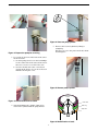
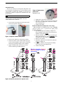
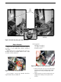
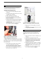
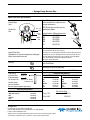
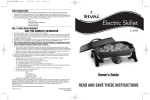
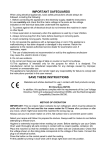
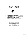
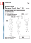
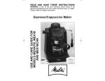
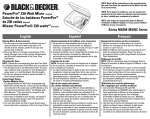
Teledyne Isco Syringe Pumps: Care and Maintenance Syringe Pump Technical Bulletin TB22 ~ Overview ~ ~ Pump Case Top Removal ~ This bulletin provides instructions for performing normal periodic maintenance required by Teledyne Isco syringe pumps, followed by servicing tasks that can be performed in the field. DANGER Risk of electric shock. Disconnect the electric power before servicing. Only trained service personnel may remove the case top. Periodic Maintenance Some maintenance and servicing procedures require accessing the pump module interior. Remove the four Phillips screws holding the case top in place (two screws on each side). Lift the cover straight up and off. Simple maintenance tasks that can be performed on-site keep your syringe pump system at optimum performance and help to avoid costly repairs. These tasks, explained in detail on the following pages, are listed in Table 1. Syringe Pump Service Kits The service kit includes the most common consumable parts replaced during periodic maintenance, as well as special tools for performing syringe pump maintenance. Detailed information about service kit contents and part numbers can be found in Table 2 on page 7. Systems with the older pump controller require a different service kit than systems with the current controller. Figure 1: Pump case top screws (2 of 4 shown) ~ Seal Replacement ~ Before cleaning or replacing the piston or wiper seals, the cylinder must first be emptied. Table 1: Periodic Maintenance Schedule Task Frequency Seal Replacement Piston & Wiper Seals - Annual (minimum) * 30 to 40 minutes Lubrication Motor Brush Set 15 minutes 20 minutes Annually or every 6,000 strokes Every two years or 6,000 strokes CAUTION Estimated Time Handle with care. Never let surfaces of seals, piston, or cylinder come into contact with abrasives or fingernails. Tools required: ● ● Note ● * Increase frequency for applications involving heavy use or harsh/abrasive substances. ● 1 /4" and 1/8" Allen wrenches #2 Phillips screwdriver Wrench set from maintenance kit Never-Seez lubricant from accessory package Removing the Pump Cylinder 1. Run the pump until empty. Note C Fa * Cylinder Cap Seal - Replace when removing/ installing cap for servicing, or periodically if cap is removed more often (e.g., for spooning in highly viscous substances). 0.000mL/MIN 0PSI 0 CYLINDER EMPTY 204.000mL/MIN F L O W R AT E 2. Disconnect the power cord and pressure transducer cables, and plumbing connections from the pump. Wrap the transducer cable around the cylinder cap. 1 Syringe Pump Technical Bulletin TB22 Figure 4: Unscrew pump cylinder 5. Remove the loosened cylinder by lifting it straight up. This gives access to the piston and seals, identified in Figure 6. Figure 2: Prepare the pump for servicing 3. Loosen the lock screw on the front of the tower about two turns. a. On older pumps, first loosen the four Phillips screws on the sides of the tower; then remove the tower cover to access the lock screw. b. On newer models, the tower cover has an opening in the front to access the lock screw without removing the cover. Figure 5: Remove pump cylinder Piston seal retainer Figure 3: Loosen lock screw on tower Piston seal 4. Attach and tighten the cylinder clamp, then unscrew the cylinder with the pump wrench. Wear ring Wiper seal Figure 6: Identification of seals 2 Syringe Pump Technical Bulletin TB22 The Piston Seal Do not use abrasives on the piston and piston seal area. Scratches caused by the use of such abrasives will cause leakage. If either the cylinder or seal has been scratched, it must be replaced to maintain flow rate specifications. Figure 8: Replacement piston seal (Spring faces up) Note If your pump uses polyethylene seals, follow the special break-in procedure described in the next section before final installation. 5. Tighten the seal retainer to 20 foot-lbs. 6. Install the cylinder over the piston assembly taking care not to damage the seal, and screw into the mounting block. 7. Leak test the pump. 1. Unscrew the seal retainer from the piston and remove the piston seal from it. Piston Seal Break-In (Aqueous seals only) This procedure is intended only for the UHMWP (aqueous) piston seal, to prevent the spring from becoming deformed. 1. Assemble the piston assembly per Figure 9A. First, install the replacement seal on the piston with the spring facing down. 2. Slide the cylinder over the piston assembly, per Figure 9B, and allow it to sit for 15 minutes. This “breaks in” the seal for the steps that follow. 3. Remove the cylinder. 4. Install the replacement seal with the spring facing up, per Figure 9C. 5. Install the cylinder over the piston assembly, and screw into the mounting block. 6. Leak test the pump. Figure 7: Separate retainer from piston 2. Remove the old piston seal from the retainer. 3. Clean the surface of the retainer with isopropyl alcohol, then install the replacement seal, spring facing up (toward the flange on the retainer). 4. Apply a small amount of Never-Seez on the retainer threads (part #60-1244-272). Break-in procedure: Aqueous Seals only. Begin w/ spring facing down. For Model 1000D, Refer to Replacement Parts Listing 60-1242-347 Figure 9: Break-in procedure for aqueous seals 3 Syringe Pump Technical Bulletin TB22 The Wear Ring Reinstalling the Piston and Pump Tower 1. Screw the piston base onto the push tube. 2. Install the piston seal retainer onto the top of the piston. 3. Replace the cylinder over the piston and push tube assembly and screw it into the cylinder mounting block. The cylinder should be screwed into the cylinder mounting block until the cylinder bottoms firmly against the stop ring on the cylinder mount (the cylinder will no longer turn). Although the wear ring does not routinely need to be replaced, it can become worn or damaged, depending on how the pump has been used. Teledyne Isco recommends that when replacing other seals or cleaning the piston, check the wear ring for any signs of deterioration. 1. Access the piston as described previously. 2. Remove the piston seal retainer and slide off the seal. The wear ring should then slide easily up and off the piston. The wear ring prevents the piston from direct metal-to-metal contact with the cylinder wall, and should, therefore, extend at least 0.010" beyond the circumference of the piston lip. Check the bottom of the wear ring, which rests on the piston lip, for extrusion or any unevenness. If there is an indentation (of 0.0010" or more) marking the outline of the piston lip, then the wear ring should be replaced. 4. Unscrew the cylinder at least 1/2-turn, until the inlet and outlet ports are lined up as before. 5. Lock the cylinder by tightening the locking screw. Reinstall covers. ~ Lubrication ~ The pump is a precision engineered instrument that must be lubricated every two years or every 6,000 strokes (whichever comes first) to ensure proper service life. The pump has an easy-to-access lube wheel that keeps the main gears lubricated during operation. To do so, first remove the pump case top as previously described on page 2. For your convenience, a lubrication kit (containing Never-seez and ALMASOL 609 lubricants) is included in your pump accessory package. See Figure 10, configuration 1 or 2, depending on your pump motor type. The Wiper Seal Although the wiper seal does not normally need to be changed, periodic cleaning is advisable. Inspect it for damage and replace if necessary. Note The following steps refer to all pump models except for the 500D, which requires internal retaining ring pliers, and a wrench from the 500D wrench package. 1. Access the cylinder as described previously. 2. Insert a round, 18" diameter metal tool into the round hole on the side of the piston. Note that the syringe pump wrench package does include such a tool. Worm/Worm Gear The worm and worm gear are lubricated by a lubrication wheel. Apply ALMASOL 609 directly to the wheel until it is saturated. The wheel may also be directly lubricated by trickling oil into the wheel while the pump is running. 3. Leverage the tool to loosen the piston, then unscrew it by hand. 4. Lift off the wiper seal. Taking care not to scratch any sealing surfaces, gently break free any solids from the seal and piston. Rinse all the solids away with distilled water or a suitable solvent. WARNING Keep fingers and foreign objects away from the gears while the pump is running. Reinstallation of seals 1. Install the piston seal onto the retainer with the spring facing up. 2. Install the wiper seal onto the piston base with the spring facing down. Note Use only ALMASOL 609 lubrication on the worm and worm gear. Do not substitute. Ball Nut The ball screw, which drives the ball nut, must be kept lubricated with Never-seez. 1. Remove the case top and front tower cover to gain access to all parts requiring lubrication. 2. To lubricate the ball nut, run the pump until the ball nut reaches its maximum height (empty). 3. Apply two beads of lubricant, on opposite sides of the ball screw, down its entire length. Note In the Model 1000D pump only, the wiper seal is installed with the spring facing up. 4 Syringe Pump Technical Bulletin TB22 Ball Screw (worm gear unseen) Worm Gear Configuration 1 Configuration 2 (65D Only) Lube Wheel Figure 10: Inside the pump: gear train lubrication Tools required: #2 Phillips screwdriver ~ Motor Brushes ~ 3 /16" Blade screwdriver Needlenose pliers Inspect the motor brushes every two years of operation, or every 6,000 piston strokes, whichever comes first. Both brushes wear at approximately the same rate; therefore only the top brush, which is more easily accessible, need be inspected. 1.1 cm Figure 12: Length of a new motor brush (1.1 cm) 1. Remove the pump case top as described in the previous section. Unscrew the brush retainer from the motor using a straight edge screwdriver. 2. Pull the brush out of the slot and measure its length. If it is nearing 0.4 cm, replace both brushes. Figure 11: Location of motor brushes A new brush is 1.1 cm long. Brushes should be replaced before they reach 0.4 cm. 5 Syringe Pump Technical Bulletin TB22 Note Alternatively, the entire motor can also be replaced. For longer-lived optimal performance, replace the motor when the brushes wear down. Remove cover plate Top Motor Brush Replacement 1. Remove the wire lead by pulling on the spade connector. 2. Unscrew the brush retainer from the motor using a straight edge screwdriver. 3. Pull the old brush out of the slot. 4. Connect the new brush to the wire lead. 5. Insert the new brush into the slot (needlenose pliers recommended). 6. Push the spring down into the slot in the motor. You may need to use the edge of the screwdriver to gently press the metal tabs on the spring down into the slot. Reinstall the brush retainer, tightening it with the screwdriver (do not overtighten). Brush retainer Figure 14: Accessing the bottom motor brush 3. Remove the wire lead by pulling on the spade connector. 4. Unscrew the brush retainer from the motor using a straight edge screwdriver. Metal tabs Note Use a larger screwdriver and/or dab some adhesive on the edge of the blade to help avoid dropping the retainer down into the bottom compartment of the pump. 5. Pull the old brush out of the slot, taking care not to drop it. 6. Connect the new brush to the wire lead. 7. Push the wire lead with your fingers to align the brush with the slot in the motor, then use the screwdriver to gently press the brush, spring, and metal tabs into the slot. 8. Holding the brush in place with the screwdriver, carefully align the brush retainer over it, sliding the screwdriver blade out from under it at the same time. 9. Reinstall the brush retainer, tightening it with the screwdriver (do not overtighten). Figure 13: Inserting new motor brush Bottom Motor Brush Replacement Newer pumps have an opening in the case bottom providing access to the bottom brush. Pumps without this opening must be sent to the factory for bottom brush replacement. 1. Lay the pump onto its back or side in order to access the opening in the case bottom. Disconnect the pressure transducer cable from the rear panel if laying the pump on its back. 2. Remove the two screws holding the small cover plate in place (refer to Figure 14). 6 Syringe Pump Technical Bulletin TB22 ~ Syringe Pump Service Kits ~ Table 2: Service Kit Contents Piston & Wiper Seals Cyl. cap seal Cylinder Cap Seal Piston seal Wiper seal Wrench Package: Various wrenches for use with most common part replacements. NOTE: Wrench types and sizes may vary between pump models. Package Numbers If Ordering Separately: 1000D 60-1247-093 500D 60-1247-068 260D 60-1247-067 100D 60-1247-067 65D 60-1247-130 (1000D only) Motor Brush Set : Control Panel Label Depending on use, the most frequently pressed keypad buttons may eventually wear out. Port Plug Inspect the top brush, which is easier to access. New brushes are 1.1 cm long. Replace both brushes before the top brush wears to a length of 0.4 cm. To access the bottom brush for replacement, remove the cover plate on the bottom of the pump. Refer to the user manual section Pump Maintenance, Troubleshooting, and Servicing for detailed instructions. Other option: replace entire motor. Cable Ties & Mounts Tubing Connectors Zero Volume Nut & Ferrule (100D/260D) Fuses Universal Sensor Harness Shear Key w/ Installation Tool - Shear key If the pump motor fails to stop in the Shear key for 65DM Installation tool event of an overpressure situation, the shear key may require replacement. 69-1244-415 Service Kit Part Numbers Legacy (Older Controller): 1000D 500D 260D 100DM/DX 65D 65DM 68-1249-104 68-1249-102 68-1249-101 68-1249-100 68-1249-111 Call Factory D-Series (Current Controller): 1000D 500D 260D 100DM/DX 65D 65DM Shear Key Part Numbers Installation Tool 1000D, 500HP, 260D, 65D 500D 100DM/DX 65DM 60-1248-135 60-1243-607 60-1243-654 60-1243-608 60-1243-949 2A fuse, 117V 1A fuse, 234V Teledyne Isco P.O. Box 82531, Lincoln, Nebraska, 68501 USA Toll-free: (800) 775-2965 • Phone: (402) 464-0231 • Fax: (402) 465-3001 E-mail: [email protected] Teledyne Isco is continually improving its products and reserves the right to change product specifications, replacement parts, schematics, and instructions without notice. Rear Panel of Pump 411-0311-62 411-0311-51 60-1247-060 60-1247-072 60-1247-073 60-1247-074 60-1247-087 60-1247-094