1
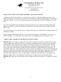
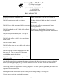
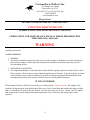
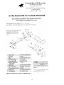
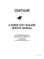
CENTAUR
6 HORSE HOT WALKER
SERVICE MANUAL
5761 RIDGEVIEW AVENUE
MIRA LOMA, CALIFORNIA 91752
(951) 685-7337 FAX (951) 685-0341
1-800-962-8050
www.hotwalkers.com
E-Mail: [email protected]
Revised 9/2004
Centaur Horse Walkers, Inc.
5761 Ridgeview Avenue
Mira Loma, Ca 91752
(951) 685-7337 • (951) 685-0341 Fax
1-800-962-8050
www.hotwalkers.com
HOT WALKER INSTALLATION & MAINTENANCE SCHEDULE
UNLOADING THE HOT WALKER
Lift the hot walker from the head only. If you must life the Hot Walker from the base, make sure that your
forks on your lift clear all drive assemblies inside the Hot Walker. You can inspect this prior to lifting by
opening up your small inspection door which is mounted on one side of your Hot Walker.
Prior to installing your Hot Walker on your pad or post holes, refer to the enclosed diagrams for the proper
layout of the bolts and your electrical source. Make sure that the walker is mounted on a fairly level surface.
BASE & ARM SET UP
After removing the Hot Walker off the trailer place it upon the appropriate slab. Remove the 3 screws on the
front panel, and the top small plate, that is on top of the cover, then remove the 3 sides of the cover that are
welded and the top that is welded so that you expose the entire drive system. This gives you easy access to do
your electrical and also your concrete anchoring so you do not damage the cover and inconvenience your
working ability.
ARM INSTALLATION
You will want to have 3 men up on 3 ladders holding the arm structure, slide one end into the 3 ½” box receiver
now insert ½” nut & bolt to flat tab. Go to the opposite side of the machine or 180 degrees, (to balance the Hot
Walker) then install a 3rd arm at 90 degrees, and then the 4th at 90 degrees, so then you have a 4 horse hot
walker, then add the other 2 arms, you now have 6 arms installed in the machine.
At the end of each major support arm either 20ft or 13ft sections (3 X 3) box, one foot back is a half inch nut
welded into the head, and there is a bolt, take the bolt out, slide the 2 ½” X 2 ½” square steel tubing arm into the
3 X 3 super structure assembly using a drift pin or screw driver in the nut hole so as the arm is passing towards
the center of the Hot Walker the drift pin or screw driver will stop the arm. When the screwdriver drops into
the hole that is drilled into the top of the short arm. At that point apply grease to the bolt & thread the bolt back
through the welded nut through the open hole in the arm, this is to secure the arm so that it doesn’t pull back
out, do this on all super structures.
2
Centaur Horse Walkers, Inc.
5761 Ridgeview Avenue
Mira Loma, Ca 91752
(951) 685-7337 • (951) 685-0341 Fax
1-800-962-8050
www.hotwalkers.com
INSTALLING YOUR SAFETY RELEASE ROPES AND ANIMAL LEADS:
On the bottom side of each arm there is a steel rod with a curled end. Take the supplied rope and tie a non
slipping knot through its steel loop. Now take the free end of the rope and feed it through the two welded rings
on the arm assembly. At the free end of the rope attach it to the ring on the vertical steel column with a good
knot.
Now take the ring end of your lead and have someone pull the safety rope which will pull the rod back and
allow you to put the ring in the arm opening, now release the rope and the lead will stay attached to the Hot
Walker Arm.
To release the animal all you need to do now is simply jerk the pull rope and the animal is released with the lead
attached to it’s halter.
Be sure to grease each spring on each arm. This allows the quick release to work properly. You can use any
WHITE GREASE. You should grease the springs at least every 60 days to insure your animal’s safety.
CABLE, CABLE CLAMPS & TURN BUCKLE INSTALLATION:
IMPORTANT: You will have to apply some vertical force upwards to the arm on the bottom side, so when
you have tightened the cable it does not sag, we strongly recommend that you take a post, a 4 X 4 post put it in
at an angle, brace it, shoving the arm up as high as you can get it, that way you can take the slack out of the
cable. When you take the post out from under the arm, it will hang down & the cable will be taut. You will
notice on the super structure there is another bolt that is threaded it lies right behind the first bolt where you
inserted the smaller arm. The secondary bolt is where you take your cable pieces, make a small loop on the end
of it with a cable clamp and a small loop on the other end with a cable clamp, and you apply them around these
additional nuts & bolts you will do 4 of them that way, looking at the diagram that is included for you on
placement of the turnbuckles. There are 2 turn buckles on the inside of the cable that will go opposite each
other on 2 of the 6, cables. By rotating the turnbuckles you will apply tension on all the other cables.
IMPORTANT: Make sure the cable clamp nuts are on tight so cable will not slip out. Turn Buckles are put on
last.
3
Centaur Horse Walkers, Inc.
5761 Ridgeview Avenue
Mira Loma, Ca 91752
(951) 685-7337 • (951) 685-0341 Fax
1-800-962-8050
www.hotwalkers.com
4
Centaur Horse Walkers, Inc.
5761 Ridgeview Avenue
Mira Loma, Ca 91752
(951) 685-7337 • (951) 685-0341 Fax
1-800-962-8050
www.hotwalkers.com
HOT WALKER LUBRICATION SCHEDULE:
Inside the Hot Walker, the vertical shaft has 2 grease fitting, plus 1 grease fitting on the hub at the base of the
Hot Walker these should be greased every 60 days.
The truck rear end should have the oil drained from it every 6 months. You can use any reclaimed oil 30, 40,
or 50 Wt. DO NOT USE GEAR OIL in it, since it turns at a low R.P.M. and is not needed. Fill the oil
through the vertical tube located on the top side of the rear end. When oil starts to come out of the breather cap
(located on the vertical rear end housing) then the Walker is filled. The Walker takes about 2 ¼ gallons to fill it
totally.
The gear box should be checked every 90 to 120 days and it should be drained and refilled with the proper
“gear oil” (see brochure).
ADJUSTING THE PROPER PULLING POWER OF YOUR HOT WALKER:
To give your Hot Walker more pulling power, you will notice 1 vertical all thread rod mounted in front of the
electric motor and the gearbox. Loosen the lower jamb nuts under the slotted motor plates on the thread rod.
Now tighten the upper nuts on the thread rod, and this will cause the motor and gear box plate assembly to tilt
downward creating more tension on the double V-belts. The 2 V-Belts should have about 1 1/16th inch of give
between the big pulley and the little pulley. Try to tighten each nut the same to keep the motor assembly plate
parallel. The vertical thread rod should be kept greased to stop rusting and allow the nuts to work smoothly.
NOTE: THE HOT WALKER MUST BE TURNING WHILE TIGHTENING THE V-BELTS.
TIGHTEN THE V-BELTS AFTER THE FIRST 5 DAYS OF USAGE. THIS IS MOST
IMPORTANT, TO PREVENT THE BELTS FROM SLIPPING. (V-Belts = 70)
REPLACEMENT PARTS:
Any parts the become worn or broken can be replaced by calling our Corporate Office at 1-800-962-8050 or
909-685-7337. Most of the parts can be shipped the same day.
For belt replacement, the sizes are listed on the backside of the belts themselves.
For motor, switch, vari-pulleys, and gearboxes all the model numbers are located on their I.D. plates, for
ordering.
5
Centaur Horse Walkers, Inc.
5761 Ridgeview Avenue
Mira Loma, Ca 91752
(951) 685-7337 • (951) 685-0341 Fax
1-800-962-8050
www.hotwalkers.com
OPERATING INSTRUCTIONS
1. The Walker is designed to walk horses for conditioning and cooling. The variable speed control is provided
to allow the option of adjust of speed for different horses needs.
2. Horses “DO” require training to walk and behave properly on a hot walker. It is not intended to be used to
break wild horses or force them to walk.
3. Leads are furnished with the walker. They should be inspected once a month, they should be replaced
immediately, if they show signs of weakness, or if they begin to fray.
4. A monthly check and tightening of all bolted parts is needed. A walker that is in constant use requires this
as a normal maintenance procedure.
5. If the V-Belts become loose, they can be tightened by adjusting the nuts on the vertical thread rod mounted
in the front of the motor.
6. Grease: Grease zerks are located on the vertical shaft. These will grease the moving parts of the drive
tower. Greasing each month is recommended. NOTE: DO NOT oil or grease the V-Belt assembly.
IMPORTANT: When greasing use Lithium grease only.
7. The walker will not reverse without stopping completely first.
8. Any electrical service should be done by a licensed electrician. 110 Volt or 220 Volt wiring is required. A
remote On/Off (wired away from the walker) switch is a required safety protection. NEVER adjust walker
speed or put hands near the V-Belt assembly unless the electrical switch is turned off.
9. Walkers are warranted for one year from the date of purchase as per attached warranty statement.
6
Centaur Horse Walkers, Inc.
5761 Ridgeview Avenue
Mira Loma, Ca 91752
(951) 685-7337 • (951) 685-0341 Fax
1-800-962-8050
www.hotwalkers.com
“DO’S AND DON’TS”
DO NOT attempt to use walker prior to being
properly secured to the foundation pad.
DO grease your walker at the grease fittings once a
month, or more often if the unit is in constant use.
DO NOT operate walker with the cabinet off.
DO have all electrical hook-ups done by a licensed
electrician.
DO NOT leave walker unattended while in operation.
DO allow the walker to stop completely before
reversing direction.
DO NOT put hands near the V-Belts while walker is
in operation.
DO make sure when less than 6 horses are being
walked that they are opposite each other on the walker.
DO NOT use a metal chain as a lead. Use rope or
nylon rope with a snap at the bottom end.
DO NOT ride or allow a child to ride a horse that is
being walked.
DO NOT oil the V-Belts.
DO NOT allow a horse to rear or buck on the walker.
DO NOT allow wiring or motor to get wet.
DO NOT open the cabinet to adjust speed or to turn
the power off. Turn the power off at the remote
switch before opening the cabinet.
DO NOT use your walker as a merry-go-round for
children or adults.
As with all electrical driven equipment, the utmost caution must be taken with regard to exposure to electrical
shock caused through a rupture of any electrical connections or wire. DO NOT allow water or moisture to
accumulate around any wiring, switches or the motor.
All moving parts of this equipment are of heavy gauge steel. DO NOT expose any portion of your body to this
equipment while it is in motion.
Moving parts can be hazardous to a person wearing loosely fitting clothing or with long hair.
Use the utmost caution in operating this equipment
7
Centaur Horse Walkers, Inc.
5761 Ridgeview Avenue
Mira Loma, Ca 91752
(951) 685-7337 • (951) 685-0341 Fax
1-800-962-8050
www.hotwalkers.com
Limited Warranty
Centaur One-Year Limited Warranty
Horse Walker Models 200, 201, 400, 401, 600, and 601, Free Flow Exercisers Models 400FF, and 600FF, and Mini-Horse
Walker Models 200, 201, 400, and 401 are warranted by Centaur Horse Walkers, Inc. to the original user against
defects in workmanship or materials under normal use for one year after the date of purchase. Any part which is
determined by Centaur to be defective in material or workmanship and returned to our authorized service location, as
Centaur designates, shipping costs prepaid, will be, as the exclusive remedy, repaired or replaced at Centaur’s option.
For limited warranty claim procedures see PROMPT DISPOSITION below. This limited warranty gives purchasers
specific legal rights, which vary, from state to state.
Limitation of Liability
To the extent allowable under applicable law, Centaur’s liability for consequential and incidental damages is expressly
disclaimed. Centaur’s liability in all events is limited to, and shall not exceed, the purchase price paid.
Warranty Disclaimer
Centaur has made a diligent effort to illustrate and describe the products in this literature accurately; however such
illustrations and description are for the sole purpose of identification, and do not express or imply a warranty that the
products are merchantable, or fit for a particular purpose, or that the products will necessarily conform to the illustrations
or descriptions.
Product Suitability
Many states and localities have codes and regulations governing sales, construction installation and/or use of products for
certain purposes, which may vary from those in neighboring areas. While Centaur attempts to assure that its products
comply with such codes it cannot guarantee compliance and cannot be responsible for how the product is installed or
used. Before purchase and use of our products, please review the product application, and national & local codes and
regulations, and be sure that the product, installation, and use will comply with the.
Certain aspects of disclaimers are not applicable to consumer products; e.g., (A) some states do not allow the exclusion or
limitation of incidental or consequential damages, so the above limitations or warranty lasts, consequently the limitations
may not apply to you; (B) Also, some states do not allow limitations on how long an implied warranty lasts, consequently
the above limitations may not apply to you; and (C) by law, during the period of the limited warranty any implied
warranties of merchantability or fitness for a particular purpose applicable to consumer products purchased by consumer,
may not be excluded or otherwise disclaimed.
Prompt Disposition
Centaur will in good faith effort for prompt correction or other adjustment with respect to any product, which proves to be
defective within limited warranty. For any product believed to be defective within limited warranty, first write or call
dealer from whom product was purchased. Dealer will be given additional directions. If unable to resolve satisfactorily
write to Centaur Horse Walkers, Inc. below, giving dealer’s name, address, date and number of dealer’s invoice, and
describing the nature of the defect. Title and risk of loss pass to buyer on delivery to common carrier. If product was
damaged in transit you, file claim with freight carrier.
8
Centaur Horse Walkers, Inc.
5761 Ridgeview Avenue
Mira Loma, Ca 91752
(951) 685-7337 • (951) 685-0341 Fax
1-800-962-8050
www.hotwalkers.com
Electra-Gear
DIVISION OF REGAL-BELOIT CORPORATION
ATTENTION KEEP WITH UNIT
LUBRICATION AND MAINTENANCE MANUAL
LUBRICATION AND MAINTENANCE MANUAL FOR HI-PRO REDUCERS,
SIZES 2400, 2410, AND 1600.
WARNING
Improper installation or operation of the reducer may cause injury to personnel, or gear failure. Read all of the
operating instructions.
A. INSTALLATION
1. GENERAL
2. The Reducer should be mounted on a flat service on the machine or foundation, securely bolted down
and accurately aligned. Shims under the mounting base should be used when required to provide a
level-mounting surface.
3. SOLID SHAFT MOUNTING
4. The output shaft should be connected to the load by flexible coupling, sprocket and chain, sheave and VBelt, or pinion. Check to insure proper alignment and tension of all loads. If sprocket, sheave, or pinion
is used, mount as close to the gear housing as possible to minimize bearing load and shaft deflection.
Overhung load must be check to make certain it does not exceed published capacity.
B. RUN-IN PERIOD
The maximum efficiency of Electra Gear Reducers is obtained after a “Run-In” period. The length of time
required will depend on the load applied and will be two to fours at rated load and considerably longer at light
loads. Overloading will not decrease the “Run-in” time but may cause severe wear. During “Run-in”, higher
than normal motor currents, higher than normal temperature, lower efficiency and output torque can be
expected.
9
Centaur Horse Walkers, Inc.
5761 Ridgeview Avenue
Mira Loma, Ca 91752
(951) 685-7337 • (951) 685-0341 Fax
1-800-962-8050
www.hotwalkers.com
C. LUBRICATION
CAUTION: Check lube level on all units.
See Paragraph F (Long Term Storage) if storing for more than 6 months.
1. All Electra Worm Reducers are shipped with the proper amount of oil for the mounting position and
input speeds ordered. Special lubes or no Factory fill can be specified, if so ordered.
2. The Factory filled lube is a non-toxic rust inhibiting AGMA 8 compound worm gear oil, suitable for an
ambient temperature of +50°F to 125°F.
3. Worm Gear Reducer oil must be used to obtain satisfactory gear and worm operating life. Select the
proper type of oil from the recommended lubricant chart depending on expected ambient temperature.
a. For Ambient temperatures below 15°F or above 125°F, refer to Factory for recommendations.
b. Worm Gear Reducer oils and compounds in accordance with AGMA specifications are
commercially available from all major oil companies.
4. Before placing in operation, make certain that the solid plugs located in the highest position on the gear
housing are replaced with a vented breather plug supplied with the unit. If the mounting position is
changed from the position ordered consult the oil level and mounting positions chart to obtain proper oil
level.
5. Drain and refill oil after first 100 hours of operation. Under normal operating conditions change oil
every 2,000 hours of operation or every 6 months thereafter, whichever occurs first.
6. The maximum input HP rating as shown in the published Rating Tables is based on a stabilized oil bath
temperature not exceeding 200°F for normal ambients. Higher oil bath temperatures or continued
operation in excess of rated in put HP will tend to shorten the useful life of a lubricant. For ambient
temperatures in excess of 125°F, special lubricants or derating of the reducer may be required. Consult
the factory or local office with complete application engineering data if this occurs.
7. Irrigation duty and other special duty reducers may have special lubricants and fill levels and special
mechanical features. These units should have special instructions included. If not, contact equipment
manufacturer (OEM) or Electra.
D. MAINTENANCE
1. This gear reducer was accurately adjusted and tested at the Factory. Care must be taken when the
gearcase is disassembled and reassembled. This should be done by an authorized service station as
damage to internal parts may result if adjusted improperly. Frequent oil level inspection with the unit
not running, (preferably when warm) should be made by removing the proper oil level plug to see that
10
Centaur Horse Walkers, Inc.
5761 Ridgeview Avenue
Mira Loma, Ca 91752
(951) 685-7337 • (951) 685-0341 Fax
1-800-962-8050
www.hotwalkers.com
the oil level is being maintained. If low (without replacing the oil level plug) add lubricant through one
of the upper openings until it comes out of the oil level hole.
E. SERVICE FACTOR
CAUTION
1. Load conditions must be within the published catalog ratings and the recommended AGMA service
factors should be used.
F. LONG TERM STORAGE (6 MONTHS UP)
1. Units should be stored indoors, in a dry, warm location.
2. Completely fill the unit with oil.
3. Rotate the input shaft so that the output shaft rotates at lease one revolution per month.
4. Completely cover the input and output shaft with RUST INHIBITOR.
5. At time of start up, drain the storage oil, install the breather, and fill to the proper oil level with the
correct lubricant for the operating condition.
G. WARRANTY (Limited)
1. The warranty will cover all of the parts in an Electra reducer for 24 months from the date of
shipment. Typical operating hours per month = 175.
2. The warranty is only for Electra parts and labor. In no event shall our liability exceed the original price
of the unit, nor does it cover cost of on site repair, installation or freight.
3. Contact the Service Department for a complete explanation as to the full warranty policies and
conditions of sale.
All dimensions, designs, and specifications are subject to change without notice.
11
Centaur Horse Walkers, Inc.
5761 Ridgeview Avenue
Mira Loma, Ca 91752
(951) 685-7337 • (951) 685-0341 Fax
1-800-962-8050
www.hotwalkers.com
This position is not recommend as the high speed oil seal must support the full head of gearcase oil.
Consult the Factory for mounting positions other than those shown above.
For the LOW SPEED applications (input RPM 800 or less) use an intermittent oil level.
For INTERMITTENT of CONTINOUS – EXTREME load duty applications, we recommend filling to 85%
level and using a 7 E.P. lubricant such as Shell Omala J-460 or equal
* Output shaft opposite from that shown on drawings.
12
Centaur Horse Walkers, Inc.
5761 Ridgeview Avenue
Mira Loma, Ca 91752
(951) 685-7337 • (951) 685-0341 Fax
1-800-962-8050
www.hotwalkers.com
13
Centaur Horse Walkers, Inc.
5761 Ridgeview Avenue
Mira Loma, Ca 91752
(951) 685-7337 • (951) 685-0341 Fax
1-800-962-8050
www.hotwalkers.com
RECOMMENDED LUBRICANTS (FOR WORM GEARS)
AMBIENT TEMP
LUBRICANT
MANUFACTURER
RANGE
NAME
Getty Refining Co.
Getty Refining Co.
Getty Refining Co.
Getty Refining Co.
Lubrication Eng. Inc.
Lubrication Eng. Inc.
Lubrication Eng. Inc.
Mobil Oil Co.
Mobil Oil Co.
Mobil Oil Co.
Shell Oil Co.
Shell Oil Co.
Shell Oil Co.
Shell Oil Co.
Texaco Inc.
Texaco Inc.
Texaco Inc.
Veedol Asreslube 98
Veedol Asreslube 95
Veedol Asreslube 90
Veedol Asreslube 86
Almasol 609
Almasol 608
Almasol 607
Mobil Extra Hecla Super
Mobil Cylinder 600 W
Mobilgear 630
Omala 460
Valvata J460
Omala 680
Valvata J680
Meropa 680
Meropa 460
Meropa 220
+ 100° to + 150° F
+ 50° to + 105° F
+ 40° to + 100° F
+ 25° to + 90° F
+ 45° to + 125° F
+ 32° to + 105° F
+ 15° to + 70° F
+ 50° to + 125° F
+ 32° to + 100° F
+ 25° to + 75° F
+ 40° to + 115° F
+ 40° to + 105° F
+ 50° to + 125° F
+ 50° to + 125° F
+ 45° to + 120° F
+ 32° to + 100° F
+ 15° to + 75° F
A.G.M.A.
RATING
8 EP
7 EP
6 EP
5 EP
8
7
5
8
7
5 EP
7 EP
7
8 EP
8
8 EP
7 EP
5 EP
SPECIAL BROAD TEMPERATURE RANGE LUBRICANTS
Electragrear International Inc.
Kendall
Mobil Oil Co.
Mobil Oil Co.
Mobil Oil Co.
Electra Lube
3 Star
Mobil SHC 634
Mobil SHC 629
Mobil SHC 626
+ 15° to + 125° F
- 10° to + 100° F
0 to + 135° F
- 25° to + 100° F
- 40° to + 40° F
-7
7 EP
5 EP
3 EP
- 40° to + 10° F
- 10° to + 40° F
- 55° to 0 F
- 30° to + 5° F
- 10° to + 40° F
- 55° to + 5° F
-3 EP
--3 EP
None
SPECIAL COLD DUTY LUBRICANTS
Conoco
Lubrication Eng. Inc.
Mobil Oil Co.
Mobil Oil Co.
Mobil Oil Co.
Shell Oil Co.
Polar Start 600
Almasol 606
Mobil SHC 624
Gargoyle Arctic Oil “C”
Mobilgear 627
Donax A.T.F. T-6
IRRIGATION DUTY, TYPICAL LUBRICANTS
Most use 85% fill (2 ¾ pints) or refer to special instructions.
Use 5EP or 7EP lubes. Reference above manufacturers.
1. Ambient temperature range is based upon 1.0 service factor.
14
+ 40° to + 115° F
+ 25° to 75° F
7 EP
5 EP
Centaur Horse Walkers, Inc.
5761 Ridgeview Avenue
Mira Loma, Ca 91752
(951) 685-7337 • (951) 685-0341 Fax
1-800-962-8050
www.hotwalkers.com
2. Above lubes are compounded for use in worm gears. Some contain noncorrosive, extreme pressure.
DO NOT USE lubes that contain sulphur and/or chlorine which are corrosive to bronze gears. Extreme
pressure lubes, in come cases, contain materials that are toxic. Avoid use of these lubes where they can
result in harmful effects. If in doubt, consult your local lube supplier.
3. Only use A.G.M.A. rated worm gear lubes.
15
Centaur Horse Walkers, Inc.
5761 Ridgeview Avenue
Mira Loma, Ca 91752
(951) 685-7337 • (951) 685-0341 Fax
1-800-962-8050
www.hotwalkers.com
Electra-Gear
Division of Regal-Beloit Corporation
WAREHOUSE OPERATIONS
FORT WAYNE
LOS ANGELES
7250 Freedom Way
Fort Wayne, Indiana 46818
Phone 219-489-2117
Fax 219-489-8177
1110 North Lemon Street
Anaheim, California 92801
Phone 714-535-6061
Fax 714-535-2489
ALLENTOWN
6520 Stonegate Drive, Suite 120
Allentown, Pennsylvania 18106
Phone 610-366-1751
Fax 610-366-1754
ELECTRA-GEAR SERVICE CENTERS
WEST COAST
WEST COAST
SERVICE CENTER
1110 North Lemon Street
Anaheim, California 92801
Phone 800-877-4327
SERVICE CENTER
6520 Stonegate Drive, Suite 120
Allentown, Pennsylvania 18106
Phone 610-366-1751
Fax 610-366-1754
U.S. FACILITIES
ANAHEIM, CALIFORNIA
1110 North Lemon Street
Anaheim, California 92801
Phone 714-535-6061
Fax 714-535-2489
16
Centaur Horse Walkers, Inc.
5761 Ridgeview Avenue
Mira Loma, Ca 91752
(951) 685-7337 • (951) 685-0341 Fax
1-800-962-8050
www.hotwalkers.com
CENTAUR
6 HORSE HOT WALKER
Concrete & Electrical
Installation Diagrams
5761 RIDGEVIEW AVENUE
MIRA LOMA, CALIFORNIA 91752
(951) 685-7337 FAX (951) 685-0341
1-800-962-8050
www.hotwalkers.com
E-Mail: [email protected]
Revised 9/2004
17
Centaur Horse Walkers, Inc.
5761 Ridgeview Avenue
Mira Loma, Ca 91752
(951) 685-7337 • (951) 685-0341 Fax
1-800-962-8050
www.hotwalkers.com
CENTAUR STANDARD 6 HORSE WALKER
CONCRETE PAD INSTALLATION
Center Point for Concrete Anchor Bolts:
A to B = 57 ½”
C to D = 57 ½”
A to C = 46 ½”
B to D = 46 ½”
Diagonals From Anchor Bolt To Anchor Bolt:
A to D = 74 ½”
B to C = 74 ½”
Anchor bolts are ¾” in diameter & can be either 18” or 24” in length
NOTE: The dimensions are from the BOLTS, not the slab.
Pad should be 6’ X 6’ Square, 3” Below Grade, and 3” Above Grade
18
Centaur Horse Walkers, Inc.
5761 Ridgeview Avenue
Mira Loma, Ca 91752
(951) 685-7337 • (951) 685-0341 Fax
1-800-962-8050
www.hotwalkers.com
BASE/PAD MEASUREMENTS
SIDE PANEL
FRONT PANEL
BACK PANEL
SIDE PANEL
Center Point for Concrete Anchors Bolts:
A to B = 57 ½”
C to D = 57 ½”
A to C = 46 ½”
B to D = 46 ½”
Diagonals From Anchor Bolt To Anchor Bolt:
A to D = 74 ½”
B to C = 74 ½”
Anchor bolts are ¾” in diameter & can be either 18” or 24” in length
NOTE: The dimensions are from the BOLTS, not the slab.
Pad should be 6’ X 6’ Square, 3” Below Grade, and 3” Above Grade
19
Centaur Horse Walkers, Inc.
5761 Ridgeview Avenue
Mira Loma, Ca 91752
(951) 685-7337 • (951) 685-0341 Fax
1-800-962-8050
www.hotwalkers.com
ELECTRICAL DIAGRAM
SIDE PANEL
FRONT PANEL
BACK PANEL
SIDE PANEL
Install ¾” PVC Conduit Schedule 40
Line A: 3 wires 10 gauge, (black, black, green, 220 Volt)
NOTE: The dimensions are from the BOLTS, not the slab.
20