1
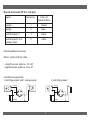
USER MANUAL SWI T C H Electronic Temperature Switch SERIES 850 Copyright All rights to these operating instructions are reserved. These operating instructions, including extracts thereof, must not be copied or translated into other languages without our written permission. Safety Instructions and Warnings Please read these instructions before installing and starting up the pressure switch. Failure to follow the instructions will make all guarantee, warranty and compensation claims null and void. connection, and the correct tools must always be used. temperature complied with. temperature • Damaged devices must not be started up. If damage occurs during operation, suitable measures must be taken to prevent persons or property from being put at risk by the damaged pressure switch. • The switch must only be repaired by NOSHOK. The accepted technical regulations and all national guidelines must always be observed and complied with. 1 Exclusion of Liability NOSHOK guarantees that the pressure switch is in perfect working condition when it is delivered. The basis consists of the technical data in the data sheet and these operating instructions. Liability cannot be accepted for the suitability of the pressure switch. Temperature Switch Description The temperature switch has one analog output and one switching output or two switching outputs. The switching output(s) is (are) adjusted using the two buttons: set point, reset point (hysteresis), switching function (normally closed/normally open contact). The programmable analog output is a special feature. It can be adjusted in 0.1° steps within a span of at least 20% of the temperature range. Electrical and Mechanical Connection The technical regulations must be complied with during installation and dismantling. The system must be depressurized prior to installation and dismantling. Safety regulations must be complied with, particularly when working on the electrical system. All connections to external electrical equipment must be made in accordance with regulations. The power to system must always be swit tch is being connected. 2 Round Connector M 12 x 1 (4-pin) Signal Connector Colors of Optional Wires Supply: + 1 brown Supply: - 3 blue Switch output S 1 4 black Switch output S 2 or analog output 2 white Recommended accessories: M12x1 socket with 2m cable • straight version, order no.: FS-2-4P • angled version, order no.: FA-2-4P switching to p potential 1 switching output and 1 analog output 2 switching outputs Sig +Supply S2 +Supply R2 S1 RL 4 3 1 2 S1 R1 -Supply -Supply 3 4 3 1 2 Switching On and Off The temperature switch is switched on when the supply voltage is applied. There is no on/off switch. A brief initialization phase occurs when the supply voltage is applied to the switch. The display and the set point LED illuminate. The measuring range (min- and max. temperature) and the unit are indicated briefly. The outputs are inactive during this time. After initialization the switch is in normal operating mode. The temperature appears on the display, the switching outputs are active and the LED’s indicate the status of the switching outputs. Programming Briefly pressing button S1 or S2 causes the relevant set point to be displayed. The status LED’s flash for as long as the set points are being displayed. Pressing the buttons for longer (press and hold down button until display flashes) causes the current temperature to be taken over as the set point. The hysteresis remains unchanged. The switching output(s) can be programmed using the control buttons independently from the present temperature, per the programming sequence on page 6. The programming sequence must run without interruptions. If delays of about 20 seconds or more occur, the switch automatically exits programming mode and switches to normal mode. All previous changes are lost. Status-LED Switching Output 1 2 4 Parameter description / programming With two switching outputs Temperature units Degree Celsius Degree Fahrenheit Switch 1, Set Point Select set point for first switch Switch 1, Reset Point Select reset point for first switch Contact 1 Select contact function for first switch normally open Select normally open contact normally closed Select normally closed contact Switch 2, Set Point Select set point for second switch Switch 2, Reset Point Select reset point for second switch Contact 2 Select contact function for second switch normally open Select normally open contact normally closed Select normally closed contact Store The previous changes are only accepted if button 2 is pressed about 15 seconds after the previous button press! 1) The pressure units setting applies immediately for the switching point settings, the reset points and for the process pressure 4-digit LED display. 5 6 With one switching output and one analog output Temperature units Degree Celsius Degree Fahrenheit Switch 1, Set Point Select set point for first switch Switch 2, Reset Point Select reset point for first switch Contact 1 Select contact function for first switch Normally open Select normally open contact Normally closed Select normally closed contact Current high Select temperature value for 20mA Current low Select temperature value for 4mA Store The previous changes are only accepted if button 2 is pressed about 15 seconds after the previous button press! 1) The pressure units setting applies immediately for the switching point settings, the reset points and for the process pressure 4-digit LED display. 7 8 Technical data Temperature Ranges -58 to +392°F -58 to +752°F -58 to +1112°F -328 to +1112°F Measurement Units °C or °F (selectable) Sensor PT100 class B or PT100 class A Supply Voltage 12...30 Vdc, overload and reverse polarity protection ripple <10% Power Consumption ≤ 50mA, without load current Process Connections • Fixed Thread • Compression Fitting Materials • Process Connection • Housing 1/2NPT, 1/4NPT 1/2NPT Other connections on request Stainless steel 1.4571 (316Ti); other materials or coatings on request Stainless steel, display cover plastic Stem and Working Pressure • from stem length (EL) 50mm: ø6 x 0.75mm (up to 40 bar) • from EL 50mm: ø8 x 1.75mm (up to 100 bar) • from EL 50mm: Special parts made of solid material (up to 500 bar) Fast response time version (up to 12 bar) • EL 25mm: ø3 x 0.25mm without taper • EL up to 100mm: ø6 x 0.25mm with taper to ø3 x 0.25mm • from EL 100mm: ø8 x 1.75mm with taper to ø6 x 0.25mm with taper to ø3 x 0.25mm Outputs 2 switching outputs PNP or 1 switching output PNP and analog output 4…20mA 9 Switching outputs • Switching function • Switching rating • Adjustment - Set Point - Reset point Analog output Signal adjustable normally closed (NC) or normally open (NO) contact 100mA per switching output Programmable via the display 0.1° steps withhin temperature range 0.1° steps from beginning temperature range until max. set point –0.1° 4…20mA; 2-wire, programmable in 0.1° steps, span at least 20% of the temperature range Load resistance Dependent on the supply voltage; the relevant formula is Display 4-digit 7-segment LED display, red, 7.6mm high Accuracy Switching output, analog output and Display: Accuracy of PT100 + 0,1% of the temperature range Repeatability 0.05% Electrical connection M12 x 1 (4-Pin) Temperature range Storage Ambient Thermal Effect -22...+176°F -13...+158°F 0.006% of Full Scale/°F EMV to IEC / EN 61 326 IEC 61000/4/2 ESD: B IEC 61000/4/3 HF: A IEC 61000/4/4 Burst: A IEC 61000/4/5 Surge: A IEC 61000/4/6 HF: A Protection class IP65 according IEC 529 Weight 0.66 lbs. 10 R= USupply − 7 V 0.022 A DIMENSIONS Inches (mm) 11 CE – Conformity The switch complies with all requirements of EN 61 326 with regard to interference emission and immunity for use in industrial areas. NOSHOK recommends the use of shielded cables. Installation and cable routing must be carried out correctly in order to maintain the effective protection from electromagnetic interference. Maintenance The temperature switches that are described in this document are maintenance free. The equipment will also operate in a stable state for long periods, meaning that regular adjustment or the like is not required. Remove the device as soon as device malfunctions start to occur. The internals cannot be maintained by the customer. Replace the device or return it to the manufacturer to have it tested. 12 Cleaning The exterior of the 850 Series Temperature Switch can be cleaned using a soft, moistened cloth. Heavy soiling can be removed using a mild cleaning agent. The switch must not be opened for cleaning! Aggressive chemicals or hard scrubbing can damage the surface, particularly the display film. Disposal The packaging and used parts must be disposed of in accordance with the regulations of the country in which the device is installed. 13 Notes: _________________________________________________________ _________________________________________________________ _________________________________________________________ _________________________________________________________ _________________________________________________________ _________________________________________________________ _________________________________________________________ _________________________________________________________ _________________________________________________________ _________________________________________________________ _________________________________________________________ _________________________________________________________ _________________________________________________________ _________________________________________________________ _________________________________________________________ 14 CORPORATE HEADQUARTERS 1010 West Bagley Road • Berea, Ohio 44017 • 440-243-0888 • FAX 440-243-3472 E-MAIL: [email protected] • WEB: www.noshok.com. NETS07