1
MicroTech® Air Cooled Screw Chiller
™
Open Protocol Data
Communications
Information Packet
Version 2.3
April, 2003
-CONFIDENTIALThis Document may not be copied or reproduced
in any way without the express written consent of
McQuay International.
NOTICE
Copyright © 1999
McQuay International, Minneapolis MN
All rights reserved throughout the world.
McQuay International reserves the right to
change any information contained herein without
prior notice. No guarantees are given as to the
accuracy of information provided.
McQuay International
Proprietary Information
Contents
REVISION HISTORY........................................................................................................................................................5
VERSION 2.2 ..........................................................................................................................................................................5
VERSION 2.1 ..........................................................................................................................................................................5
VERSION 2.0 ..........................................................................................................................................................................5
VERSION 1.2 ..........................................................................................................................................................................5
VERSION 1.1 ..........................................................................................................................................................................6
VERSION 1.0 ..........................................................................................................................................................................6
OVERVIEW ........................................................................................................................................................................7
COMPATIBLE UNIT CONTROL SOFTWARE FOR OPEN PROTOCOL ............................................................................................7
TYPICAL OPEN PROTOCOL CONTROL FUNCTIONS ..................................................................................................................8
Remote Start/Stop of the Chiller .......................................................................................................................................8
Chilled Water Reset...........................................................................................................................................................8
Demand Limit....................................................................................................................................................................8
Remote Alarm Clearing ....................................................................................................................................................9
NETWORK CONFIGURATION ...................................................................................................................................................9
Communications to a Single Chiller .................................................................................................................................9
Communications to Two or More Chillers......................................................................................................................10
SUPPLEMENTAL LITERATURE.................................................................................................................................12
CONVERSIONS AND CONVENTIONS .......................................................................................................................12
CONVERTING 2 BYTE VARIABLES ........................................................................................................................................12
NOTE ON TEMPERATURES ....................................................................................................................................................13
NOTE ON PRESSURES ...........................................................................................................................................................13
OPM - OPEN PROTOCOL MASTER PANEL.............................................................................................................13
READ ONLY MEMORY LOCATIONS (1-COMPRESSOR CHILLERS). ERROR! BOOKMARK NOT DEFINED.
READ/WRITE MEMORY LOCATIONS (1-COMPRESSOR CHILLERS)ERROR! BOOKMARK NOT DEFINED.
READ ONLY MEMORY LOCATIONS (2-COMPRESSOR CHILLERS)................................................................14
READ/WRITE MEMORY LOCATIONS (2-COMPRESSOR CHILLERS) .............................................................21
READ ONLY MEMORY LOCATIONS (3-COMPRESSOR CHILLERS)................................................................25
READ/WRITE MEMORY LOCATIONS (3-COMPRESSOR CHILLERS) .............................................................36
READ ONLY MEMORY LOCATIONS (4-COMPRESSOR CHILLERS)................................................................39
READ/WRITE MEMORY LOCATIONS (4-COMPRESSOR CHILLERS) .............................................................51
REQUIRED DEVELOPMENT TESTING TOOLS ......................................................................................................55
MicroTech Air Cooled Screw Chiller Open Protocol • Version 2.3
3
McQuay International
Proprietary Information
SETUP OF HARDWARE FOR TESTING.................................................................................................................................... 55
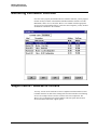
SIMULATOR MONITOR SOFTWARE GUIDE......................................................................................................... 57
OVERVIEW .......................................................................................................................................................................... 57
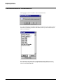
LOGGING ON TO THE SOFTWARE .......................................................................................................................................... 57
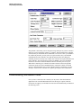
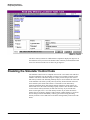
COMMUNICATIONS INITIALIZATION ..................................................................................................................................... 58
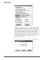
DOWNLOADING SIMULATION CODE ..................................................................................................................................... 59
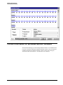
MONITORING A SIMULATOR CONTROLLER ........................................................................................................................... 61
SUPPORT MENU - READ/WRITE SCREENS ........................................................................................................................... 61
DISABLING THE SIMULATOR CONTROL CODE...................................................................................................................... 62
FURTHER INFORMATION ON WINDOWS MONITOR SOFTWARE............................................................................................. 63
GLOSSARY OF TERMS ................................................................................................................................................ 64
MicroTech Air Cooled Screw Chiller Open Protocol • Version 2.3
4
McQuay International
Proprietary Information
Revision History
Version 2.3
Made changes for the version 30 code
Remove single compressor because there isn’t any version 30 code for single
compressor screw chillers
Version 2.2
Corrected Alarm memory locations, all codes
Updated valid software idents
Version 2.1
Changed title from MicroTech® StarGate™ Screw Chiller to MicroTech® Air Cooled
Screw Chiller
Removed all references to StarGate™
Corrected Clear Circuit #3 Alarm memory location
Updated valid software idents
Version 2.0
Added single compressor screw chiller.
Added 4 compressor screw chiller.
Removed %RLA read only point for all 4 chillers
Version 1.2
I/O configurations and memory locations
MicroTech Air Cooled Screw Chiller Open Protocol • Version 2.3
5
McQuay International
Proprietary Information
have been added for 4-Compressor Chillers.
Memory locations of Conditions at Time of
Alarm have been revised for 3-Compressor
Chillers.
Version 1.1
This is a formatting revision only.
Version 1.0
The initial release of the document.
MicroTech Air Cooled Screw Chiller Open Protocol • Version 2.3
6
McQuay International
Proprietary Information
Overview
Compatible Unit Control Software for Open Protocol
The McQuay Open Protocol™ for air-cooled screw chillers allows other automation
integrators to communicate with a network of screw chillers or a single screw chiller
and obtain useful operating information through communication "reads" to the
controller. In addition, remote control of the screw chiller is possible by
communication "writes" to the controller of new setpoints and commands.
Air-cooled screw chillers included in this Open Protocol Document. McQuay
International manufactures four different MicroTech® air-cooled screw chillers.
Their software configurations are summarized as follows:
Configuration
Unit Model Number
Software IDENT
The asterisk ‘*’ is a
Two-Compressor
ALS 125* through 204*
SC2??30*
wildcard; any character
Three-compressor
ALS 205* through 280*
SC3??30*
is valid
Four-compressor
ALS 300* through 425*
SC4??30*
Software IDENT varies depending on the refrigerant type (first ‘?’ in IDENT is
either be 2, 3 or 6; the second ‘?’ in the IDENT could either be U, E or S, it is the
system of units to be displayed on the unit keypad. It does not matter what the ??
values are in terms of the points listed later in this document.
Because of the different functionality of each software configuration, memory
locations and therefore the Open Protocol interfaces to the four possible MicroTech
chillers are slightly different.
The Open Protocol integrator must know which software configuration the screw
chiller is using to know which Open Protocol memory locations are applicable. The
selling McQuay representative knows this information. If the unit is already installed,
the IDENT information may be read directly off of the unit’s keypad display.
MicroTech Air Cooled Screw Chiller Open Protocol • Version 2.3
7
McQuay International
Proprietary Information
Hexadecimal values are
indicated by a preceding
‘$’
In addition, software IDENTs are stored within the controllers in memory locations
$0A08-$0A0F. The above IDENTs result when the memory locations are translated
into ASCII. For example, control processor code for a two-compressor chiller might
be “SC23U20N” which would be represented as: $53, $43, $32, $33, $55, $32, $30,
$4E.
Typical Open Protocol Control Functions
The Open Protocol allows automation integrators to achieve many control functions
that in the past would require hardwired interfaces between the building automation
system (BAS) and the chiller. Using Open Protocol, it is possible to eliminate much
of the expensive field wiring and provide the interface through communications.
These are the typical Open Protocol control functions:
•
Remote start/stop of the chiller
•
Chilled water reset
•
Demand limit
•
Remote alarm clearing
Remote Start/Stop of the Chiller
Using communication "writes" to the "Network Command" memory location, the
McQuay® MicroTech chiller may be commanded to be enabled or disabled. This is
the preferred method of remotely turning the chiller on or off. When the "Network
Command" is "Disable," the LCD display on the chiller will show
"Off:RemoteComm."
The memory for "Network Command" is a RAM location that, upon loss and
subsequent restoration of power, is initialized to "Enable." Thus the automation
system should refresh this memory location to the desired state on a frequent basis,
such as every minute.
A standard feature of the MicroTech controller is an output dedicated to control of
the chiller's evaporator pump. We recommend using this output to control the pump.
Chilled Water Reset
Chilled water reset is achieved quite easily through communications. See the
Network Evaporator Leaving Water Temperature Setpoint.
Demand Limit
An automation system can establish the maximum number of cooling stages that can
be active for the chiller through the "Network Demand Limit" setpoint. This is vital
for systems that seek to reduce chiller capacity at certain times to avoid peak
electrical demand charges.
MicroTech Air Cooled Screw Chiller Open Protocol • Version 2.3
8
McQuay International
Proprietary Information
Remote Alarm Clearing
The automation system can clear an active alarm in the MicroTech chiller through
communications. Care should be exercised so that alarms are cleared only by
authorized individuals and only when the cause of the alarm has been corrected
and/or repaired.
Network Configuration
This section explains how the McQuay International screw Chiller Open Protocol
Network works so that you can choose the correct equipment and program your
system to communicate through McQuay International's MicroTech Open Protocol.
There are two scenarios for connecting to the controllers that are used to make an
Open Protocol Screw Chiller Network. They are as follows:
•
Communications to a single chiller
•
Communications to two or more chillers
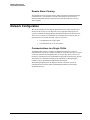
Communications to a Single Chiller
All McQuay MicroTech screw chillers are shipped from the factory with one
communications port factory-configured for RS-232, 9600 baud. The port is located
on the unit controller and is designated Port A. The port may also be accessed via
RS-485 by replacing the factory installed RS-232 plug with an RS-485 plug. The RS485 plug may be constructed according to the Open Protocol Wiring Diagram
booklet, or may be purchased through McQuay International.
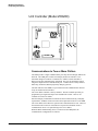
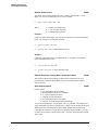
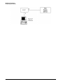
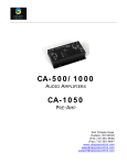
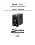
The following diagram shows the chiller-to-network connections on Port B;
communications between the chiller and Building Automation System (BAS)
established on Port A.
MicroTech Air Cooled Screw Chiller Open Protocol • Version 2.3
9
McQuay International
Proprietary Information
Unit Controller (Model 250/280)
Communications to Two or More Chillers
The OPM provides a single communications port entry into the McQuay MicroTech
Network. The OPM panel consists of a McQuay model 120 controller. The
automation integrator connects to Comm Port A, which is switch selectable to
RS-232 or RS-485 communications, 9600 baud. Port A is the automation control
integrator's Open Protocol communications port. Comm Port B is a daisy chained,
multi-drop, 9600 baud, RS-485 proprietary McQuay protocol.
The main function of the OPM is to provide the network communications interface
for up to 64 MicroTech controllers.
The screw chiller controller is factory mounted. The unit controller provides preprogrammed, pre-engineered and pre-tested stand-alone control. There is one
controller for each screw chiller.
Once the McQuay communication network has been commissioned (by a McQuay
representative, the BAS vendor can connect their Open Protocol device to the OPM.
The screw chillers will continue to operate when communications are lost. However,
the network must be intact for read and write requests from the BAS vendor’s
communication device to be passed along to the screw chillers.
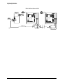
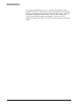
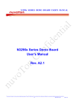
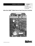
When the BAS communicating device is connected to the OPM panel, the
communications configuration is as follows:
MicroTech Air Cooled Screw Chiller Open Protocol • Version 2.3
10
McQuay International
Proprietary Information
OPM MCB and Screw MCB
MicroTech Air Cooled Screw Chiller Open Protocol • Version 2.3
11
McQuay International
Proprietary Information
Supplemental Literature
It is the objective of this document to give an overview of the screw chiller and to
document the available points offered through Open Protocol. It is strongly
recommended that the following documentation be used in conjunction with this
document. A detailed sequence of operation is described in the Operation and
Maintenance (OM) manual (if available). Unit wiring details are given in the
Installation and Maintenance manual (if available). Open Protocol wiring details and
diagrams for connectors are given in the Open Protocol Wiring Diagrams booklet.
The generic Open Protocol Data Information Packet explains the how to access via
the McQuay MicroTech protocol.
Ver 1.4
IOMMALS
CD573875Y
Open Protocol Data Information Packet
Installation & Maintenance Data
Open Protocol Wiring Diagrams
Apr, 96
Feb, 98
Jun, 98
Conversions and Conventions
Converting 2 Byte Variables
In the following read only and read/write tables, a 2-byte variable address is indicated
by a dash (-). The first memory location listed will always be the high byte and the
second memory location listed will be the low byte. For example, $04DB-C, $04DB
is the high byte and $04DC is the low byte.
Two byte variables use the following conversion unless otherwise specified:
MicroTech Air Cooled Screw Chiller Open Protocol • Version 2.3
12
McQuay International
Proprietary Information
Value = HiByte*255+LoByte.
HiByte and LoByte are the decimal equivalents of the hex byte. The Value may need
to be further processed by the given conversion to get the final result in the units
specified.
Note on Temperatures
All temperatures given above are in degrees Fahrenheit, to get degrees Celsius, you
must use the standard formula for temperature conversion:
ºC = (5/9) * (ºF -32)
Note on Pressures
All pressures given above are in PSI, to get KPA, you must use the following
standard conversion:
KPA = 6.89*PSI
OPM - Open Protocol Master
Panel
There is only one memory location that can be read in the Open Protocol Master
Panel. It is used to verify that the OPM is powered and communicating, and that the
applications code is intact.
Open Protocol Master Status
0-254 = Program is running
255 = Program is not running
MicroTech Air Cooled Screw Chiller Open Protocol • Version 2.3
$0400
13
McQuay International
Proprietary Information
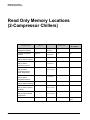
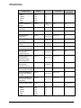
Read Only Memory Locations
(2-Compressor Chillers)
Variable Name
Range
Address
Units/
Description
Conversion
Active Chilled Water
Temperature Setpoint
$045A
30 - 160
(15-80°F)
X/2
°F
Circuit #1 Condenser
Pressure
$0467-8
0-4500
(0-450 PSI)
X/10
PSI
Circuit #1 Conditions at
Time of Alarm: Capacity
$1F13
0-100
Circuit #1 Conditions at
Time of Alarm:
Condenser Pressure
$1F09-A
0-4500
(0-450 PSI)
Circuit #1 Conditions at
Time of Alarm:
Evaporator Leaving
Water Temperature
$1F0F-10
600-3630
(X/10)-100
(-40 to 263°F)
°F
Circuit #1 Conditions at
Time of Alarm:
Evaporator Pressure
$1F07-8
0-1500
(0-150 PSI)
PSI
$1F14
Circuit #1 Conditions at
Time of Alarm: Fan Stage
Percent
X/10
X/10
PSI
0-6
Circuit #1 Conditions at
Time of Alarm: Outdoor
Air Temp
$1F11-2
600-3630
(X/10)-100
(-40 to 263°F)
°F
Circuit #1 Conditions at
Time of Alarm: Suction
Temperature
$1F0B-C
600-3630
(X/10)-100
(-40 to 263°F)
°F
Circuit #1 Current Alarm
$08B9
0 – 35
See alarm list
below
MicroTech Air Cooled Screw Chiller Open Protocol • Version 2.3
14
McQuay International
Proprietary Information
Variable Name
Circuit #1 Current Alarm
Hour
Minute
Month
Date
Year
Range
Address
Units/
Description
Conversion
$1F02
$1F01
$1F05
$1F04
$1F06
$0463-4
0-23
0-59
1-12
1-31
0-99
0-1500
(0-150 PSI)
Circuit #1 Discharge
Temperature
Circuit #1 Status
$0479-A
600-3630
(X/10)-100
(-40 to 263°F)
°F
$0428
0 – 13
See circuit status
list below
Circuit #1 Suction
Temperature
$0475-6
600-3630
(X/10)-100
(-40 to 263°F)
°F
Circuit #1 Superheat
Temperature
$04D7-8
0-2360
(0 to 263°F)
X/10
°F
Circuit #2 Condenser
Pressure
$0469-A
0-4500
(0-450 PSI)
X/10
PSI
Circuit #2 Conditions at
Time of Alarm: Capacity
$2013
0-100
Circuit #2 Conditions at
Time of Alarm:
Condenser Pressure
$2009-A
0-4500
(0-450 PSI)
Circuit #2 Conditions at
Time of Alarm:
Evaporator Leaving
Water Temperature
$200F-10
600-3630
(X/10)-100
(-40 to 263°F)
°F
Circuit #2 Conditions at
Time of Alarm:
Evaporator Pressure
$2007-8
0-1500
(0-150 PSI)
PSI
Circuit #1 Evaporator
Pressure
$2014
Circuit #2 Conditions at
Time of Alarm: Fan Stage
X/10
PSI
Percent
X/10
X/10
PSI
0-6
Circuit #2 Conditions at
Time of Alarm: Outdoor
Air Temp
$2011-2
600-3630
(X/10)-100
(-40 to 263°F)
°F
Circuit #2 Conditions at
Time of Alarm: Suction
Temperature
$200B-C
600-3630
(X/10)-100
(-40 to 263°F)
°F
Circuit #2 Current Alarm
$08BA
0 – 35
See alarm list
below
Circuit #2 Current Alarm
Hour
Minute
Month
Date
Year
$2002
$2001
$2005
$2004
$2006
0-23
0-59
1-12
1-31
0-99
MicroTech Air Cooled Screw Chiller Open Protocol • Version 2.3
15
McQuay International
Proprietary Information
Variable Name
Address
Range
Conversion
Units/
Description
PSI
Circuit #2 Evaporator
Pressure
$0465-6
0-1500
(0-150 PSI)
Circuit #2 Discharge
Temperature
Circuit #2 Status
$047B-C
600-3630
(X/10)-100
(-40 to 263°F)
°F
$0429
0 - 13
See circuit status
list below
Circuit #2 Suction
Temperature
$0477-8
600-3630
(X/10)-100
(-40 to 263°F)
°F
Circuit #2 Superheat
Temperature
$04D9-A
0-2360
(0 to 263°F)
°F
Compressor #1 Operating
Hours
$0862-3
0 - 65279
Hours
Compressor #1 Starts
$086A-B
0 - 65279
Starts
Compressor #2 Operating
Hours
$0864 -5
0 - 65279
Hours
Compressor #2 Starts
$086C -D
0 - 65279
Starts
Evaporator Entering
Water Temperature
$046E -F
600-3630
(X/10)-100
(-40 to 263°F)
°F
Evaporator Leaving
Water Temperature
$0461-2
600-3630
(X/10)-100
(-40 to 263°F)
°F
Outdoor Air Temperature
$047D-E
°F
Stage of Cooling
$042B
600-3630
(X/10)-100
(-40 to 263°F)
0-8
Unit Status
$0427
0 - 14
See unit status list
below
X/10
X/10
Active Chilled Water Temperature Setpoint
$045A
The setpoint used by the chiller to control the leaving water temperature. This is the
combination of setpoint and reset values
Circuit #1 Condenser Pressure
$0467/$0468
Measured pressure in condenser in circuit #1.
Circuit #1 Conditions at Time of Alarm: Capacity
$1F13
Capacity at which circuit #1 was running at time of alarm occurrence.
Circuit #1 Conditions at Time of Alarm: Condenser Pressure
$1F09/$1F0A
Condenser pressure in circuit #1 at time of alarm occurrence.
Circuit #1 Conditions at Time of Alarm: Evaporator Leaving Water
Temperature
$1F0F/$1F10
Evaporator leaving water temperature at time of circuit #1 alarm occurrence.
MicroTech Air Cooled Screw Chiller Open Protocol • Version 2.3
16
McQuay International
Proprietary Information
Circuit #1 Conditions at Time of Alarm: Evaporator Pressure
$1F07/$1F08
Evaporator pressure in circuit #1 at time of alarm occurrence.
Circuit #1 Conditions at Time of Alarm: Fan Stage
$1F14
Fan stage in operation at time of circuit #1 alarm occurrence. Maximum fan stages
per model:
ALS125-140
ALS155-170
ALS175-204
4
5
6
Circuit #1 Conditions at Time of Alarm: Outdoor Air Temp $1F11/$1F12
Outdoor air temperature at time of circuit #1 alarm occurrence.
Circuit #1 Conditions at Time of Alarm: Suction Temperature
$1F0B/$1F0C
Measured temperature in circuit #1 suction line at time of alarm occurrence.
Circuit #1 Current Alarm
Alarm Name
No Alarms
Interstage Solenoid Valve Open
High Condenser Pre-Alarm Hold Stage
High Condenser Pre-Alarm Stage Down
Freeze Refrigerant Pre-Alarm Stage Down
Loss Of Chilled Water Flow
No Pump Down
Low Evap No Start
Pre-purge Fail
Low Ambient Start
High Discharge Temp
(not used)
Refrigerant Freeze Protect
Low Evaporator Pressure
Motor Protect
Re-power After Power Loss
(not used)
(not used)
No Evap Press Drop
Low Lift Pressure
Low Oil Level
No Liquid Start
High Liquid Press Drop
(not used)
(not used)
High Condenser Pressure
Mechanical High Pressure
(not used)
MicroTech Air Cooled Screw Chiller Open Protocol • Version 2.3
$08B9
Active
0
1
2
3
4
5
6
7
8
9
10
11
12
13
14
15
16
17
18
19
20
21
22
23
24
25
26
27
17
McQuay International
Proprietary Information
Alarm Name
Bad Discharge Temp Sensor
Bad Compressor Suction Temp Sensor
Bad Evaporator Pressure Sensor
Bad Condenser Pressure Sensor
Bad Phase Voltage
Chilled Water Freeze Protect
Bad Voltage Ratio
Bad Leaving Evap Temp Sensor
Circuit #1 Current Alarm Hour...Year
Active
28
29
30
31
32
33
34
35
$1F01-1F06
These locations contain the time (hour and minute) and date (day, month and year)
that the alarm occurred.
Circuit #1 Evaporator Pressure
$0463/$0464
Measured pressure in evaporator in circuit #1.
Circuit #1 Discharge Temperature
$0479/$047A
This location contains the temperature, in °F, of the compressor discharge refrigerant.
Circuit #1 Status
$0428
Defined values:
0 = Off, S-1 System Switch
1 = Off, Manual Setpoint
2 = Off, Alarm
3 = Off, Pump Down Switch
4 = Off, Wait For Cycle Timers
5 = Off, Wait For Flood Timer
6 = Off, Ready to Start
7 = Start Pump Down
8 = Pump Down
9 = Start Requested
10 = Pre-purge
11 = Open Solenoid
12 = Low Ambient Start
13 = Cooling
Circuit #1 Suction Temperature
$0475/$0476
This location contains the temperature, in °F, of the low-pressure vaporized
refrigerant entering the compressor.
Circuit #1 Superheat Temperature
$04D7/$04D8
This location contains the Superheat Temperature in °F. The superheat temperature
is calculated by subtracting the evaporator refrigerant temperature from the Suction
Temperature.
Circuit #2 Condenser Pressure
$0469/$046A
Measured pressure in condenser in circuit #2.
MicroTech Air Cooled Screw Chiller Open Protocol • Version 2.3
18
McQuay International
Proprietary Information
Circuit #2 Conditions at Time of Alarm: Capacity
$2013
Capacity at which circuit #2 was running at time of alarm occurrence.
Circuit #2 Conditions at Time of Alarm: Condenser Pressure
$2009/$200A
Condenser pressure in circuit #2 at time of alarm occurrence.
Circuit #2 Conditions at Time of Alarm: Evaporator Leaving Water
Temperature
$200F/$2010
Evaporator leaving water temperature at time of circuit #2 alarm occurrence.
Circuit #2 Conditions at Time of Alarm: Evaporator Pressure
$2007/$2008
Evaporator pressure in circuit #2 at time of alarm occurrence.
Circuit #2 Conditions at Time of Alarm: Fan Stage
$2014
Fan stage in operation at time of circuit #2 alarm occurrence. Maximum fan stages
per model:
ALS125-140
ALS155-170
ALS175-204
4
5
6
Circuit #2 Conditions at Time of Alarm: Outdoor Air Temp $2011/$2012
Outdoor air temperature at time of circuit #2 alarm occurrence.
Circuit #2 Conditions at Time of Alarm: Suction Temperature
$200B/$200C
Measured temperature in circuit #1 suction line at time of alarm occurrence.
Circuit #2 Current Alarm
$08BA
Same as Circuit #1 Above
Circuit #2 Current Alarm Hour...Year
$2001-2006
These locations contain the time (hour and minute) and date (day, month and year)
that the alarm occurred.
Circuit #2 Evaporator Pressure
$0465/$0466
Measured pressure in evaporator in circuit #2.
Circuit #2 jDischarge Temperature
$047B/$047C
This location contains the temperature, in °F, of the compressor discharge refrigerant.
Circuit #2 Status
$0429
Same as Circuit #1 Above
Circuit #2 Suction Temperature
$0477/$0478
This location contains the temperature, in °F, of the low-pressure vaporized
refrigerant entering the compressor.
MicroTech Air Cooled Screw Chiller Open Protocol • Version 2.3
19
McQuay International
Proprietary Information
Circuit #2 Superheat Temperature
$04D9/$04DA
This location contains the Condenser Superheat Temperature in °F. The superheat
temperature is calculated by subtracting the evaporator refrigerant temperature from
the Suction Temperature.
Compressor #1 Operating Hours
$0862/$0863
Cumulative total of operating hours for compressor #1.
Compressor #1 Starts
$086A/$086B
Running total of starts for compressor #1.
Compressor #2 Operating Hours
$0864/$0865
Cumulative total of operating hours for compressor #2.
Compressor #2 Starts
$086C/$086D
Running total of starts for compressor #2.
Evaporator Entering Water Temperature
$046E/$046F
This location contains the temperature, in °F, of the chilled water entering the
evaporator.
Evaporator Leaving Water Temperature
$0461/$0462
This location contains the temperature, in °F, of the chilled water leaving the
evaporator.
Outdoor Air Temperature
$047D/$047E
This location contains the ambient temperature, in °F, of the outdoor air.
Stage of Cooling
$042B
Stage of cooling capacity at which the chiller is currently operating.
Unit Status
$0427
Defined values:
0 = Off, Manual Setpoint
1 = Off, S-1 System Switch
2 = Off, Remote Communication
3 = Off, Remote Switch
4 = Off, Time Schedule
5 = Off, Alarm
6 = Off, Pump Down Switches
7 = Off, Ambient Lock
8 = Starting
9 = Waiting For Flow
10 = Waiting For Load
11 = Cool Stage Up
12 = Cool Stage Down
13 = Cooling
14 = Manual Cool Staging
MicroTech Air Cooled Screw Chiller Open Protocol • Version 2.3
20
McQuay International
Proprietary Information
Read/Write Memory Locations
(2-Compressor Chillers)
Variable Name
Range
Address
Conversion
Units
$091A
0-1
$091B
0-1
Evaporator Entering Water
Temperature Setpoint
$090D
30 - 160
(15-80°F)
X/2
°F
Evaporator Leaving Water
Temperature Setpoint
$0905
20 - 160
(10-80°F)
X/2
°F
Maximum Chilled Water
Reset Setpoint
$090C
0 - 90
(0-45°F)
X/2
°F
Network Command
0=Enable
1=Disable
Network Demand Limit
$044F
0-1
$044D
0 - 100
Percent
Network Evaporator Leaving
Water Temperature Reset
$044E
0 - 100
Percent
Reset Option Setpoint
$090B
0-5
Clear Circuit #1 Alarm
1 = Clear Active Alarm
0 = Do Nothing
Clear Circuit #2 Alarm
1 = Clear Active Alarm
0 = Do Nothing
Clear Circuit #1 Alarm
$091A
1 = Clear Active Alarm
0 = Do Nothing
Memory location will change to zero when alarm is cleared.
MicroTech Air Cooled Screw Chiller Open Protocol • Version 2.3
21
McQuay International
Proprietary Information
Clear Circuit #2 Alarm
$091B
1 = Clear Active Alarm
0 = Do Nothing
Memory location will change to zero when alarm is cleared.
Evaporator Entering Water Temperature Setpoint
$090D
Temperature setpoints are not stored as direct representations of a temperature. They
are stored as temperature * 2. This will allows temperatures to be specified in 0.5°F
increments.
Example: 54.5°F is stored as 109 decimal.
Default value of Evaporator Entering Water Temperature Setpoint is 108 (54°F).
Evaporator Leaving Water Temperature Setpoint
$0905
Default value of Evaporator Leaving Water Temperature Setpoint is 88 (44°F).
Maximum Chilled Water Reset Setpoint
$090C
Default value of Maximum Chilled Water Reset Setpoint is 20 (10°F).
Network Command
$044F
The Network Command is a way to disable the chiller through the Open Protocol
interface. If all other enable/disable features are in the "enabled" position, writing a
"1" to the Network Command memory location will disable the chiller. If any of the
enable/disable features is in the "disabled" position, the Network Command will have
no effect. The memory for Network Command is a RAM location that, upon loss and
subsequent restoration of power, is initialized to "Enable."
MicroTech Air Cooled Screw Chiller Open Protocol • Version 2.3
22
McQuay International
Proprietary Information
Network Demand Limit
$044D
The chiller can be Demand Limited two ways - either by a hardwired 4 - 20 mA
signal or by network communications. Here is the formula:
C - {[(C-1) * (%S + %N)] + 50} / 100
Where:
C = Number of cooling stages
S = 4 - 20 mA range in percent
N = Network range in percent
Example 1:
If there are eight cooling stages, and "50" has been written to the Network Demand
Limit. (No external 4 - 20 mA signal is wired).
8 – {[(8-1) * ( 0+50)] + 50}/ 100
8 - {[7*50] + 50} / 100 = 4 stages Maximum Limit
Example 2:
If there are eight cooling stages, the input from the 4 - 20 signal is 8 mA and the
Network Demand Limit is zero.
8 - {[(8-1) * (25+0)] + 50} / 100
8 - {[7*25] + 50} / 100 = 6 stages Maximum Limit
Network Evaporator Leaving Water Temperature Reset
$044E
This location contains the percentage of chilled water temperature reset to be
performed when Network Chilled Water Reset is selected as the Reset Option
Setpoint (below).
Reset Option Setpoint
$090B
Possible values:
0 = No Chilled Water Reset (default)
1 = Return Chilled Water Reset (see I&M)
2 = 4 - 20 mA Chilled Water Reset
3 = Network Chilled Water Reset
4 = Ice Chilled Water Reset (see I&M)
5 = Outdoor Air Temperature Chilled Water Reset
To reset from a hardwired 4 - 20 mA signal, write "2" to $090B. The chilled water
supply temperature will then be controlled from a range of 44°F (Evaporator Leaving
Water Setpoint) to 54°F [Maximum Chilled Water Temperature Reset Setpoint
(10°F) plus the Evaporator Leaving Water Temperature Setpoint (44°F)]. At 4 mA
or below, the temperature setpoint will be 44°F. At 20 mA, the temperature setpoint
will be 54°F.
MicroTech Air Cooled Screw Chiller Open Protocol • Version 2.3
23
McQuay International
Proprietary Information
To reset through communication, write "3" to $090B. The chilled water supply
temperature will then be controlled from a range of 44°F (Evaporator Leaving Water
Setpoint) to 54°F [Maximum Chilled Water Temperature Reset (10°F) + Evaporator
Leaving Water Temperature Setpoint (44°F)]. You may write 0 through 100
(% reset) to the Network Evaporator Leaving Reset. If you write a "0," the
temperature setpoint will be 44°F. If you write a "100," the temperature setpoint will
be 54°F.
MicroTech Air Cooled Screw Chiller Open Protocol • Version 2.3
24
McQuay International
Proprietary Information
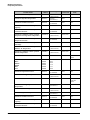
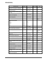
Read Only Memory Locations
(3-Compressor Chillers)
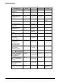
Variable Name
Range
Address
Conversion
Units
Active Chilled Water
Temperature Setpoint
$045A
30 - 160
(15-80°F)
X/2
°F
Circuit #1 Condenser
Pressure
$0467-8
0-4500
(0-450 PSI)
X/10
PSI
Circuit #1 Conditions at
Time of Alarm: Capacity
$1C13
0-100
Circuit #1 Conditions at
Time of Alarm:
Condenser Pressure
$1C09-A
0-4500
(0-450 PSI)
X/10
PSI
Circuit #1 Conditions at
Time of Alarm:
Evaporator Leaving
Water Temperature
$1C0F-10
600-3630
(-40 to 263°F)
(X/10)-100
°F
Circuit #1 Conditions at
Time of Alarm:
Evaporator Pressure
$1C07-8
0-1500
(0-150 PSI)
X/10
PSI
$1C14
Circuit #1 Conditions at
Time of Alarm: Fan Stage
Percent
0-5
Circuit #1 Conditions at
Time of Alarm: Outdoor
Air Temp
$1C11-2
600-3630
(-40 to 263°F)
(X/10)-100
°F
Circuit #1 Conditions at
Time of Alarm: Suction
Temperature
$1C0B-C
600-3630
(-40 to 263°F)
(X/10)-100
°F
Circuit #1 Current Alarm
$08B9
0 – 35
Circuit #1 Current Alarm
Hour
Minute
Month
Date
Year
$1C02
$1C01
$1C05
$1C04
$1C06
0-23
0-59
1-12
1-31
0-99
MicroTech Air Cooled Screw Chiller Open Protocol • Version 2.3
See alarm list
below
25
McQuay International
Proprietary Information
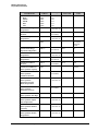
Variable Name
Range
Address
Conversion
Units
Circuit #1 Discharge
Temperature
$0487-8
600-3630
(-40 to 263°F)
(X/10)-100
°F
Circuit #1 Evaporator
Pressure
$0463-4
0-1500
(0-150 PSI)
X/10
PSI
Circuit #1 Liquid Line
Temperature
Circuit #1 Status
$0479-A
600-3630
(-40 to 263°F)
(X/10)-100
°F
$0428
0 - 13
Circuit #1 Discharge
Superheat Temperature
$04DF-E0
0-2360
(0 to 263°F)
X/10
°F
Circuit #1 Suction
Temperature
$0475-6
600-3630
(-40 to 263°F)
(X/10)-100
°F
Circuit #1 Superheat
Temperature
$04D7-8
0-2360
(0 to 263°F)
X/10
°F
Circuit #2 Condenser
Pressure
$0469-A
0-4500
(0-450 PSI)
X/10
PSI
Circuit #2 Conditions at
Time of Alarm: Capacity
$1D13
0-100
Circuit #2 Conditions at
Time of Alarm:
Condenser Pressure
$1D09-A
0-4500
(0-450 PSI)
X/10
PSI
Circuit #2 Conditions at
Time of Alarm:
Evaporator Leaving
Water Temperature
$1D0F-10
600-3630
(-40 to 263°F)
(X/10)-100
°F
Circuit #2 Conditions at
Time of Alarm:
Evaporator Pressure
$1D07-8
0-1500
(0-150 PSI)
X/10
PSI
$1D14
Circuit #2 Conditions at
Time of Alarm: Fan Stage
See status list
below
Percent
0-5
Circuit #2 Conditions at
Time of Alarm: Liquid
Line Temperature
$1D0D-E
600-3630
(-40 to 263°F)
(X/10)-100
°F
Circuit #2 Conditions at
Time of Alarm: Outdoor
Air Temp
$D011-2
600-3630
(-40 to 263°F)
(X/10)-100
°F
Circuit #2 Conditions at
Time of Alarm: Suction
Temperature
$1D0B-C
600-3630
(-40 to 263°F)
(X/10)-100
°F
Circuit #2 Current Alarm
$08BA
0 – 35
MicroTech Air Cooled Screw Chiller Open Protocol • Version 2.3
See alarm list
below
26
McQuay International
Proprietary Information
Variable Name
Circuit #2 Current Alarm
Hour
Minute
Month
Date
Year
Range
Address
$1D02
$1D01
$1D05
$1D04
$1D06
$0489-A
0-23
0-59
1-12
1-31
0-99
600-3630
(-40 to 263°F)
Circuit #2 Evaporator
Pressure
$0465-6
Circuit #2 Liquid Line
Temperature
Circuit #2 Status
Conversion
Units
(X/10)-100
°F
0-1500
(0-150 PSI)
X/10
PSI
$047B-C
600-3630
(-40 to 263°F)
(X/10)-100
°F
$0429
0 - 13
Circuit #2 Discharge
Superheat Temperature
$04E1-2
0-2360
(0 to 263°F)
X/10
°F
Circuit #2 Suction
Temperature
$0477-8
600-3630
(-40 to 263°F)
(X/10)-100
°F
Circuit #2 Superheat
Temperature
$04D9-A
0-2360
(0 to 263°F)
X/10
°F
Circuit #3 Condenser
Pressure
$0481-2
0-4500
(0-450 PSI)
X/10
PSI
Circuit #3 Conditions at
Time of Alarm: Capacity
$1E13
0-100
Circuit #3 Conditions at
Time of Alarm:
Condenser Pressure
$1E09-A
0-4500
(0-450 PSI)
X/10
PSI
Circuit #3 Conditions at
Time of Alarm:
Evaporator Leaving
Water Temperature
$1E0F-10
600-3630
(-40 to 263°F)
(X/10)-100
°F
Circuit #3 Conditions at
Time of Alarm:
Evaporator Pressure
$1E07-8
0-1500
(0-150 PSI)
X/10
PSI
Circuit #2 Discharge
Temperature
$1E14
Circuit #3 Conditions at
Time of Alarm: Fan Stage
See circuit
status list
below
Percent
0-5
Circuit #3 Conditions at
Time of Alarm: Liquid
Line Temperature
$1E0D-E
600-3630
(-40 to 263°F)
(X/10)-100
°F
Circuit #3 Conditions at
Time of Alarm: Outdoor
Air Temp
$1E11-2
600-3630
(-40 to 263°F)
(X/10)-100
°F
Circuit #3 Conditions at
Time of Alarm: Suction
Temperature
$1E0B-C
600-3630
(-40 to 263°F)
(X/10)-100
°F
MicroTech Air Cooled Screw Chiller Open Protocol • Version 2.3
27
McQuay International
Proprietary Information
Variable Name
Address
Range
Circuit #3 Current Alarm
$08BE
0 - 35
Circuit #3 Current Alarm
Hour
Minute
Month
Date
Year
$1E02
$1E01
$1E05
$1E04
$1E06
0-23
0-59
1-12
1-31
0-99
600-3630
(-40 to 263°F)
Circuit #3 Discharge
Temperature
$049B-C
Circuit #3 Evaporator
Pressure
$047F-80
Circuit #3 Liquid Line
Temperature
Circuit #3 Status
Conversion
Units
See alarm list
below
(X/10)-100
°F
0-1500
(0-150 PSI)
X/10
PSI
$0485-6
600-3630
(-40 to 263°F)
(X/10)-100
°F
$042A
0 - 13
Circuit #3 Discharge
Superheat Temperature
$04E9-A
0-2360
(0 to 263°F)
X/10
°F
Circuit #3 Suction
Temperature
$0483-4
600-3630
(-40 to 263°F)
(X/10)-100
°F
Circuit #3 Superheat
Temperature
$04E5-6
0-2360
(0 to 263°F)
X/10
°F
Compressor #1 Operating
Hours
$0862-3
0 - 65279
Hours
Compressor #1 Starts
$086A-B
0 - 65279
Starts
Compressor #2 Operating
Hours
$0864-5
0 - 65279
Hours
Compressor #2 Starts
$086C-D
0 - 65279
Starts
Compressor #3 Operating
Hours
$0866-7
0 - 65279
Hours
Compressor #3 Starts
$086E-F
0 - 65279
Starts
Evaporator Entering
Water Temperature
$046E-F
600-3630
(-40 to 263°F)
(X/10)-100
°F
Evaporator Leaving
Water Temperature
$0461-2
600-3630
(-40 to 263°F)
(X/10)-100
°F
Outdoor Air Temperature
$0470-1
(X/10)-100
°F
Stage of Cooling
$042B
600-3630
(-40 to 263°F)
0 – 12
Unit Status
$0427
0 - 14
See circuit
status list
below
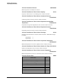
Active Chilled Water Temperature Setpoint
See unit status
list below
$045A
The setpoint used by the chiller to control the leaving water temperature. This is the
combination of setpoint and reset values
MicroTech Air Cooled Screw Chiller Open Protocol • Version 2.3
28
McQuay International
Proprietary Information
Circuit #1 Condenser Pressure
$0467/$0468
Measured pressure in condenser in circuit #1.
Circuit #1 Conditions at Time of Alarm: Capacity
$1C13
Capacity at which circuit #1 was running at time of alarm occurrence.
Circuit #1 Conditions at Time of Alarm: Condenser Pressure
$1C09/$1C0A
Condenser pressure in circuit #1 at time of alarm occurrence.
Circuit #1 Conditions at Time of Alarm: Evaporator Leaving Water
Temperature
$1C0F/$1C10
Evaporator leaving water temperature at time of circuit #1 alarm occurrence.
Circuit #1 Conditions at Time of Alarm: Evaporator Pressure
$1C07/$1C08
Evaporator pressure in circuit #1 at time of alarm occurrence.
Circuit #1 Conditions at Time of Alarm: Fan Stage
$1C14
Fan stage in operation at time of circuit #1 alarm occurrence. Maximum fan stages
per model:
ALS205-220
ALS235-280
4
5
Circuit #1 Conditions at Time of Alarm: Liquid Line Temperature
$1C0D/$1C0E
Measured temperature in circuit #1 liquid line at time of alarm occurrence.
Circuit #1 Conditions at Time of Alarm: Outdoor Air Temp $1C11/$1C12
Outdoor air temperature at time of circuit #1 alarm occurrence.
Circuit #1 Conditions at Time of Alarm: Suction Temperature
$1C0B/$1C0C
Measured temperature in circuit #1 suction line at time of alarm occurrence.
Circuit #1 Current Alarm
Alarm Name
No Alarms
High Condenser Pre-Alarm Hold Stage
High Condenser Pre-Alarm Stage Down
Freeze Refrigerant Pre-Alarm Stage Down
Loss Of Chilled Water Flow
No Pump Down
Low Evap No Start
Pre-purge Fail
(not used)
Low Ambient Start
(not used)
MicroTech Air Cooled Screw Chiller Open Protocol • Version 2.3
$08B9
Active
0,1
2
3
4
5
6
7
8
9
10
11
29
McQuay International
Proprietary Information
Alarm Name
Refrigerant Freeze Protect
Low Evaporator Pressure
Starter Fault
Re-power After Power Loss
(not used)
(not used)
No Evap Press Drop
Low Lift Pressure
No Liquid Run
No Liquid Start
High Liquid Press Drop
(not used)
High Discharge Temp
High Condenser Pressure
Mechanical High Pressure
(not used)
Bad Discharge Temp Sensor
Bad Compressor Suction Temp Sensor
Bad Evaporator Pressure Sensor
Bad Condenser Pressure Sensor
Bad Phase Voltage
Chilled Water Freeze Protect
Bad Voltage Ratio
Bad Leaving Evap Temp Sensor
Circuit #1 Current Alarm Hour...Year
Active
12
13
14
15
16
17
18
19
20
21
22
23
24
25
26
27
28
29
30
31
32
33
34
35
$1C01-1C06
These locations contain the time (hour and minute) and date (day, month and year)
that the alarm occurred.
Circuit #1 Discharge Temperature
$0487/$0488
This location contains the temperature, in °F, of the high-pressure vaporized
refrigerant leaving the compressor.
Circuit #1 Evaporator Pressure
$0463/$0464
Measured pressure in evaporator in circuit #1.
Circuit #1 Liquid Line Temperature
$0479/$047A
This location contains the temperature, in °F, of the liquid refrigerant entering the
expansion valve.
MicroTech Air Cooled Screw Chiller Open Protocol • Version 2.3
30
McQuay International
Proprietary Information
Circuit #1 Status
$0428
Defined values:
0 = Off, S-1 System Switch
1 = Off, Manual Setpoint
2 = Off, Alarm
3 = Off, Pump Down Switch
4 = Off, Wait For Cycle Timers
5 = Off, Wait For Flood Timer
6 = Off, Ready
7 = Start Pump Down
8 = Pump Down
9 = Start Requested
10 = Pre-purge
11 = Open Solenoid
12 = Low Ambient Start
13 = Cooling
Circuit #1 Discharge Superheat Temperature
$04DF/$04E0
This location contains the Discharge Superheat Temperature in °F. The Discharge
Superheat Temperature is calculated by subtracting the condenser refrigerant
Temperature from the discharge temperature.
Circuit #1 Suction Temperature
$0475/$0476
This location contains the temperature, in °F, of the low-pressure vaporized
refrigerant entering the compressor.
Circuit #1 Superheat Temperature
$04D7/$04D8
This location contains the Superheat Temperature in °F. The superheat temperature
is calculated by subtracting the evaporator refrigerant temperature from the Suction
Temperature.
Circuit #2 Condenser Pressure
$0469/$046A
Measured pressure in condenser in circuit #2.
Circuit #2 Conditions at Time of Alarm: Capacity
$1D13
Capacity at which circuit #2 was running at time of alarm occurrence.
Circuit #2 Conditions at Time of Alarm: Condenser Pressure
$1D09/$1D0A
Condenser pressure in circuit #2 at time of alarm occurrence.
Circuit #2 Conditions at Time of Alarm: Evaporator Leaving Water
Temperature
$1D0F/$1D10
Evaporator leaving water temperature at time of circuit #2 alarm occurrence.
Circuit #2 Conditions at Time of Alarm: Evaporator Pressure
$1D07/$1D08
Evaporator pressure in circuit #2 at time of alarm occurrence.
MicroTech Air Cooled Screw Chiller Open Protocol • Version 2.3
31
McQuay International
Proprietary Information
Circuit #2 Conditions at Time of Alarm: Fan Stage
$1D14
Fan stage in operation at time of circuit #2 alarm occurrence. Maximum fan stages
per model:
ALS205-220
ALS235-280
4
5
Circuit #2 Conditions at Time of Alarm: Liquid Line Temperature
$1D0D/$1D0E
Measured temperature in circuit #2 liquid line at time of alarm occurrence.
Circuit #2 Conditions at Time of Alarm: Outdoor Air Temp $1D11/$1D12
Outdoor air temperature at time of circuit #2 alarm occurrence.
Circuit #2 Conditions at Time of Alarm: Suction Temperature
$1D0B/$1D0C
Measured temperature in circuit #2 suction line at time of alarm occurrence.
Circuit #2 Current Alarm
$08BA
Same as Circuit #1 Above
Circuit #2 Current Alarm Hour...Year
$1D01-1D06
These locations contain the time (hour and minute) and date (day, month and year)
that the alarm occurred.
Circuit #2 Discharge Temperature
$0489/$048A
This location contains the temperature, in °F, of the high-pressure vaporized
refrigerant leaving the compressor.
Circuit #2 Evaporator Pressure
$0465/$0466
Measured pressure in evaporator in circuit #2.
Circuit #2 Liquid Line Temperature
$047B/$047C
This location contains the temperature, in °F, of the liquid refrigerant entering the
expansion valve.
Circuit #2 Status
$0429
Same as Circuit #1 above
Circuit #2 Discharge Superheat Temperature
$04E1/$04E2
This location contains the Discharge Superheat Temperature in °F. The Discharge
Superheat Temperature is calculated by subtracting the condenser refrigerant
Temperature from the discharge temperature.
Circuit #2 Suction Temperature
$0477/$0478
This location contains the temperature, in °F, of the low-pressure vaporized
refrigerant entering the compressor.
MicroTech Air Cooled Screw Chiller Open Protocol • Version 2.3
32
McQuay International
Proprietary Information
Circuit #2 Superheat Temperature
$04D9/$04DA
This location contains the Superheat Temperature in °F. The superheat temperature
is calculated by subtracting the evaporator refrigerant temperature from the Suction
Temperature.
Circuit #3 Condenser Pressure
$0481/$0482
Measured pressure in condenser in circuit #3.
Circuit #3 Conditions at Time of Alarm: Capacity
$1E13
Capacity at which circuit #3 was running at time of alarm occurrence.
Circuit #3 Conditions at Time of Alarm: Condenser Pressure
$1E09/$1E0A
Condenser pressure in circuit #3 at time of alarm occurrence.
Circuit #3 Conditions at Time of Alarm: Evaporator Leaving Water
Temperature
$1E0F/$1E10
Evaporator leaving water temperature at time of circuit #3 alarm occurrence.
Circuit #3 Conditions at Time of Alarm: Evaporator Pressure
$1E07/$1E08
Evaporator pressure in circuit #3 at time of alarm occurrence.
Circuit #3 Conditions at Time of Alarm: Fan Stage
$1E14
Fan stage in operation at time of circuit #3 alarm occurrence. Maximum fan stages
per model:
ALS205-220
ALS235-280
4
5
Circuit #3 Conditions at Time of Alarm: Liquid Line Temperature
$1E0D/$1E0E
Measured temperature in circuit #3 liquid line at time of alarm occurrence.
Circuit #3 Conditions at Time of Alarm: Outdoor Air Temp $1E11/$1E12
Outdoor air temperature at time of circuit #3 alarm occurrence.
Circuit #3 Conditions at Time of Alarm: Suction Temperature
$1E0B/$1E0C
Measured temperature in circuit #3 suction line at time of alarm occurrence.
Circuit #3 Current Alarm
$08BE
Same as Circuit #1 Above
Circuit #3 Current Alarm Hour...Year
$1E01-1E06
These locations contain the time (hour and minute) and date (day, month and year)
that the alarm occurred.
MicroTech Air Cooled Screw Chiller Open Protocol • Version 2.3
33
McQuay International
Proprietary Information
Circuit #3 Discharge Temperature
$049B/$049C
This location contains the temperature, in °F, of the high-pressure vaporized
refrigerant leaving the compressor.
Circuit #3 Evaporator Pressure
$047F/$0480
Measured pressure in evaporator in circuit #3.
Circuit #3 Liquid Line Temperature
$0485/$0486
This location contains the temperature, in °F, of the liquid refrigerant entering the
expansion valve.
Circuit #3 Status
$042A
Same as Compressor #1 and #2 above.
Circuit #3 Discharge Superheat Temperature
$04E9/$04EA
This location contains the Discharge Superheat Temperature in °F. The Discharge
Superheat Temperature is calculated by subtracting the condenser refrigerant
Temperature from the discharge temperature.
Circuit #3 Suction Temperature
$0483/$0484
This location contains the temperature, in °F, of the low-pressure vaporized
refrigerant entering the compressor.
Circuit #3 Superheat Temperature
$04E5/$04E6
This location contains the Superheat Temperature in °F. The superheat temperature
is calculated by subtracting the evaporator refrigerant temperature from the Suction
Temperature.
Compressor #1 Operating Hours
$0862/$0863
Cumulative total of operating hours for compressor #1.
Compressor #1 Starts
$086A/$086B
Running total of starts for compressor #1.
Compressor #2 Operating Hours
$0864/$0865
Cumulative total of operating hours for compressor #2.
Compressor #2 Starts
$086C/$086D
Running total of starts for compressor #2.
Compressor #3 Operating Hours
$0866/$0867
Cumulative total of operating hours for compressor #3.
Compressor #3 Starts
$086E/$086F
Running total of starts for compressor #3.
MicroTech Air Cooled Screw Chiller Open Protocol • Version 2.3
34
McQuay International
Proprietary Information
Evaporator Entering Water Temperature
$046E/$046F
This location contains the temperature, in °F, of the chilled water entering the
evaporator.
Evaporator Leaving Water Temperature
$0461/$0462
This location contains the temperature, in °F, of the chilled water leaving the
evaporator.
Outdoor Air Temperature
$0470/$0471
This location contains the ambient temperature, in °F, of the outdoor air. (Applies to
air cooled units only.)
Stage of Cooling
$042B
Stage of cooling capacity at which the chiller is currently operating.
Unit Status
$0427
Defined values:
0 = Off, Manual Setpoint
1 = Off, S-1 System Switch
2 = Off, Remote Communication
3 = Off, Remote Switch
4 = Off, Time Schedule
5 = Off, Alarm
6 = Off, Pump Down Switches
7 = Off, Ambient Lock
8 = Starting
9 = Waiting For Flow
10 = Waiting For Load
11 = Cool Stage Up
12 = Cool Stage Down
13 = Cooling
14 = Manual Cool Staging
MicroTech Air Cooled Screw Chiller Open Protocol • Version 2.3
35
McQuay International
Proprietary Information
Read/Write Memory Locations
(3-Compressor Chillers)
Variable Name
Address
Range
Conversion
Units
Clear Circuit #1 Alarm
$091A
0–1
Clear Circuit #2 Alarm
$091B
0–1
Clear Circuit #3 Alarm
$091F
0–1
Evaporator Entering Water
Temperature Setpoint
$090D
30 – 160
(15°F – 80°F)
X/2
°F
Evaporator Leaving Water
Temperature Setpoint
$0905
20 – 160
(10°F – 80°F)
X/2
°F
Maximum Chilled Water Reset
Setpoint
$090C
0 – 90
(0°F – 45°F)
X/2
°F
Network Command
$044F
0–1
0 = Enable
1 = Disable
Network Demand Limit
$044D
0 - 100%
Percent
Network Evaporator Leaving
Water Temperature Reset
$044E
0 - 100%
Percent
Reset Option Setpoint
$090B
0–5
Clear Circuit #1 Alarm
$091A
1 = Clear Active Alarm
0 = Do Nothing
Memory location will change to zero when alarm is cleared.
Clear Circuit #2 Alarm
$091B
1 = Clear Active Alarm
0 = Do Nothing
Memory location will change to zero when alarm is cleared.
Clear Circuit #3 Alarm
$091F
1 = Clear Active Alarm
0 = Do Nothing
Memory location will change to zero when alarm is cleared.
MicroTech Air Cooled Screw Chiller Open Protocol • Version 2.3
36
McQuay International
Proprietary Information
Evaporator Entering Water Temperature Setpoint
$090D
Temperature setpoints are not stored as direct representations of a temperature. They are
stored as temperature * 2. This will allows temperatures to be specified in 0.5°F
increments.
Example: 54.5°F is stored as 109 decimal.
Default value of Evaporator Entering Water Temperature Setpoint is 108 (54°F).
Evaporator Leaving Water Temperature Setpoint
$0905
Default value of Evaporator Leaving Water Temperature Setpoint is 88 (44°F).
Maximum Chilled Water Reset Setpoint
$090C
Default value of Maximum Chilled Water Reset Setpoint is 20 (10°F).
Network Command
$044F
The Network Command is a way to disable the chiller through the Open Protocol interface.
If all other enable/disable features are in the "enabled" position, writing a "1" to the
Network Command memory location will disable the chiller. If any of the enable/disable
features is in the "disabled" position, the Network Command will have no effect. The
memory for Network Command is a RAM location that, upon loss and subsequent
restoration of power, is initialized to "Enable."
MicroTech Air Cooled Screw Chiller Open Protocol • Version 2.3
37
McQuay International
Proprietary Information
Network Demand Limit
$044D
The chiller can be Demand Limited two ways - either by a hardwired 4 - 20 mA signal or
by network communications. Here is the formula:
C - {[(C-1) * (%S + %N)] + 50} / 100
Where:
C = Number of cooling stages
S = 4 - 20 mA range in percent
N = Network range in percent
Example 1:
If there are twelve cooling stages, and "50" has been written to the Network Demand
Limit. (No external 4 - 20 mA signal is wired).
12 – {[(12-1) * ( 0+50)] + 50}/ 100
12 - {[11*50] + 50} / 100 = 6 stages Maximum Limit
Example 2:
If there are twelve cooling stages, the input from the 4 - 20 signal is 8 mA and the
Network Demand Limit is zero.
12 - {[(12-1) * (25+0)] + 50} / 100
12 - {[11*25] + 50} / 100 = 9 stages Maximum Limit
Network Evaporator Leaving Water Temperature Reset
$044E
This location contains the percentage of chilled water temperature reset to be performed
when Network Chilled Water Reset is selected as the Reset Option Setpoint (below).
Reset Option Setpoint
$090B
Possible values:
0 = No Chilled Water Reset (default)
1 = Return Chilled Water Reset (see I&M)
2 = 4 - 20 mA Chilled Water Reset
3 = Network Chilled Water Reset
4 = Ice Chilled Water Reset (see I&M)
5 = Outdoor Air Temperature Chilled Water Reset
To reset from a hardwired 4 - 20 mA signal, write "2" to $090B. The chilled water
supply temperature will then be controlled from a range of 44°F (Evaporator Leaving
Water Setpoint) to 54°F [Maximum Chilled Water Temperature Reset Setpoint (10°F)
plus the Evaporator Leaving Water Temperature Setpoint (44°F)]. At 4 mA or below, the
temperature setpoint will be 44°F. At 20 mA the temperature setpoint will be 54°F.
To reset through communication, write "3" to $090B. The chilled water supply
temperature will then be controlled from a range of 44°F (Evaporator Leaving Water
Setpoint) to 54°F [Maximum Chilled Water Temperature Reset (10°F) + Evaporator
Leaving Water Temperature Setpoint (44°F)]. You may write 0 through 100 (% reset) to
the Network Evaporator Leaving Reset. If you write a "0," the temperature setpoint will
be 44°F. If you write a "100," the temperature setpoint will be 54°F.
MicroTech Air Cooled Screw Chiller Open Protocol • Version 2.3
38
McQuay International
Proprietary Information
Read Only Memory Locations
(4-Compressor Chillers)
Variable Name
Range
Address
Conversion
Units
Active Chilled Water Temperature
Setpoint
$045A
30 - 160
(15-80°F)
Circuit #1 Condenser Pressure
$0467-8
X/10
Circuit #1 Conditions at Time of Alarm:
Capacity
$1C13
0-4500
(0-450 PSI)
0-100
Circuit #1 Conditions at Time of Alarm:
Condenser Pressure
$1C09-A
0-4500
(0-450 PSI)
X/10
PSI
Circuit #1 Conditions at Time of Alarm:
Evaporator Leaving Water Temperature
$1C0F-10
600-3630
(-40 to 263°F)
(X/10)-100
°F
Circuit #1 Conditions at Time of Alarm:
Evaporator Pressure
$1C07-8
0-1500
(0-150 PSI)
X/10
PSI
Circuit #1 Conditions at Time of Alarm:
Fan Stage
$1C14
0-5
Circuit #1 Conditions at Time of Alarm:
Outdoor Air Temperature
$1C11-2
600-3630
(-40 to 263°F)
(X/10)-100
°F
Circuit #1 Conditions at Time of Alarm:
Suction Temperature
$1C0B-C
600-3630
(-40 to 263°F)
(X/10)-100
°F
Circuit #1 Current Alarm
$08B9
0 – 35
Circuit #1 Current Alarm
Hour
Minute
Month
Date
Year
$1C02
$1C01
$1C05
$1C04
$1C06
Circuit #1 Evaporator Pressure
$0463-4
Circuit #1 Discharge Temperature
$0479-A
Circuit #1 Status
$0428
0-23
0-59
1-12
1-31
0-99
0-1500
(0-150 PSI)
600-3630
(-40 to 263°F)
0 - 13
Circuit #1 Discharge Superheat
Temperature
$04DF-E0
MicroTech Air Cooled Screw Chiller Open Protocol • Version 2.3
0-2360
(0 to 263°F)
X/2
°F
PSI
Percent
See alarm list
below
X/10
PSI
(X/10)-100
°F
See circuit
status list
below
X/10
°F
39
McQuay International
Proprietary Information
Variable Name
Range
Address
Conversion
Units
600-3630
(-40 to 263°F)
0-2360
(0 to 263°F)
0-4500
(0-450 PSI)
0-100
(X/10)-100
°F
X/10
°F
X/10
PSI
$1D09-A
0-4500
(0-450 PSI)
X/10
PSI
Circuit #2 Conditions at Time of Alarm:
Evaporator Leaving Water Temperature
$1D0F-10
600-3630
(-40 to 263°F)
(X/10)-100
°F
Circuit #2 Conditions at Time of Alarm:
Evaporator Pressure
$1D07-8
0-1500
(0-150 PSI)
X/10
PSI
Circuit #2 Conditions at Time of Alarm:
Fan Stage
$1D14
0-5
Circuit #2 Conditions at Time of Alarm:
Outdoor Air Temperature
$1D11-2
600-3630
(-40 to 263°F)
(X/10)-100
°F
Circuit #2 Conditions at Time of Alarm:
Suction Temperature
$1D0B-C
600-3630
(-40 to 263°F)
(X/10)-100
°F
Circuit #2 Current Alarm
$08BA
0 – 35
Circuit #2 Current Alarm
Hour
Minute
Month
Date
Year
$1D02
$1D01
$1D05
$1D04
$1D06
0-23
0-59
1-12
1-31
0-99
Circuit #2 Evaporator Pressure
$0465-6
X/10
PSI
Circuit #2 Discharge Temperature
$047B-C
(X/10)-100
°F
Circuit #2 Status
$0429
0-1500
(0-150 PSI)
600-3630
(-40 to 263°F)
0 - 13
Circuit #2 Discharge Superheat
Temperature
$04E1-2
0-2360
(0 to 263°F)
X/10
°F
Circuit #2 Suction Temperature
$0477-8
(X/10)-100
°F
Circuit #2 Superheat Temperature
$04D9-A
X/10
°F
Circuit #3 Condenser Pressure
$0481-2
X/10
PSI
Circuit #3 Conditions at Time of Alarm:
Capacity
$1E13
600-3630
(-40 to 263°F)
0-2360
(0 to 263°F)
0-4500
(0-450 PSI)
0-100
Circuit #3 Conditions at Time of Alarm:
Condenser Pressure
$1E09-A
0-4500
(0-450 PSI)
X/10
Circuit #1 Suction Temperature
$0475-6
Circuit #1 Superheat Temperature
$04D7-8
Circuit #2 Condenser Pressure
$0469-A
Circuit #2 Conditions at Time of Alarm:
Capacity
$1D13
Circuit #2 Conditions at Time of Alarm:
Condenser Pressure
MicroTech Air Cooled Screw Chiller Open Protocol • Version 2.3
Percent
See alarm list
below
See circuit
status list
below
Percent
PSI
40
McQuay International
Proprietary Information
Variable Name
Range
Address
Conversion
Units
Circuit #3 Conditions at Time of Alarm:
Evaporator Leaving Water Temperature
$1E0F-10
600-3630
(-40 to 263°F)
(X/10)-100
°F
Circuit #3 Conditions at Time of Alarm:
Evaporator Pressure
$1E07-8
0-1500
(0-450 PSI)
X/10
PSI
Circuit #3 Conditions at Time of Alarm:
Fan Stage
$1E14
0-5
Circuit #3 Conditions at Time of Alarm:
Outdoor Air Temperature
$1E11-2
600-3630
(-40 to 263°F)
(X/10)-100
°F
Circuit #3 Conditions at Time of Alarm:
Suction Temperature
$1E0B-C
600-3630
(-40 to 263°F)
(X/10)-100
°F
Circuit #3 Current Alarm
$08BE
1 - 35; 129 - 163
Circuit #3 Current Alarm
Hour
Minute
Month
Date
Year
$1E02
$1E01
$1E05
$1E04
$1E06
Circuit #3 Evaporator Pressure
$047F-80
Circuit #3 Discharge Temperature
$0485-6
Circuit #3 Status
$042A
0-23
0-59
1-12
1-31
0-99
0-1500
(0-150 PSI)
600-3630
(-40 to 263°F)
0 - 13
Circuit #3 Discharge Superheat
Temperature
$04E9-A
0-2360
(0 to 263°F)
X/10
°F
Circuit #3 Suction Temperature
$0483-4
(X/10)-100
°F
Circuit #3 Superheat Temperature
$04E5-6
X/10
°F
Circuit #4 Condenser Pressure
$0489-A
X/10
PSI
Circuit #4 Conditions at Time of Alarm:
Capacity
$1F13
600-3630
(-40 to 263°F)
0-2360
(0 to 263°F)
0-4500
(0-450 PSI)
0-100
Circuit #4 Conditions at Time of Alarm:
Condenser Pressure
$1F09-A
0-4500
(0-450 PSI)
X/10
PSI
Circuit #4 Conditions at Time of Alarm:
Evaporator Leaving Water Temperature
$1F0F-10
600-3630
(-40 to 263°F)
(X/10)-100
°F
Circuit #4 Conditions at Time of Alarm:
Evaporator Pressure
$1F07-8
0-1500
(0-150 PSI)
X/10
PSI
Circuit #4 Conditions at Time of Alarm:
Fan Stage
$1F14
0-5
Circuit #4 Conditions at Time of Alarm:
Outdoor Air Temperature
$1F11-2
600-3630
(-40 to 263°F)
(X/10)-100
°F
MicroTech Air Cooled Screw Chiller Open Protocol • Version 2.3
See alarm list
below
X/10
PSI
(X/10)-100
°F
See circuit
status list
below
Percent
41
McQuay International
Proprietary Information
Variable Name
Address
Range
Conversion
Units
Circuit #4 Conditions at Time of Alarm:
Suction Temperature
$1F0B-C
600-3630
(-40 to 263°F)
Circuit #4 Current Alarm
$08B7
1 - 35; 129 - 163
Circuit #4 Current Alarm
Hour
Minute
Month
Date
Year
$1F02
$1F01
$1F05
$1F04
$1F06
Circuit #4 Evaporator Pressure
$0487-8
Circuit #4 Discharge Temperature
$049D-E
Circuit #4 Status
$0430
0-23
0-59
1-12
1-31
0-99
0-1500
(0-150 PSI)
600-3630
(-40 to 263°F)
0 - 13
Circuit #4 Discharge Superheat
Temperature
$04EB-C
0-2360
(0 to 263°F)
X/10
°F
Circuit #4 Suction Temperature
$049B-C
(X/10)-100
°F
Circuit #4 Superheat Temperature
$04E7-8
X/10
°F
Compressor #1 Operating Hours
$0862-3
600-3630
(-40 to 263°F)
0-2360
(0 to 263°F)
0 - 65279
Compressor #1 Starts
$086A-B
0 - 65279
Starts
Compressor #2 Operating Hours
$0864-5
0 - 65279
Hours
$086C-D
0 - 65279
Starts
$0866-7
0 - 65279
Hours
$086E-F
0 - 65279
Starts
Compressor #4 Operating Hours
$0868-9
0 - 65279
Hours
Compressor #4 Starts
$0870-1
0 - 65279
Starts
Evaporator Entering Water Temperature
$046E-F
Evaporator Leaving Water Temperature
$0461-2
Outdoor Air Temperature
$0470-1
Stage of Cooling
$042B
600-3630
(-40 to 263°F)
600-3630
(-40 to 263°F)
600-3630
(-40 to 263°F)
0 – 16
Unit Status
$0427
0 – 14
Compressor #2 Starts
Compressor #3 Operating Hours
Compressor #3 Starts
Active Chilled Water Temperature Setpoint
(X/10)-100
°F
See alarm list
below
X/10
PSI
(X/10)-100
°F
See circuit
status list
below
Hours
(X/10)-100
°F
(X/10)-100
°F
(X/10)-100
°F
See unit status
list below
$045A
The setpoint used by the chiller to control the leaving water temperature. This is the
combination of setpoint and reset values
MicroTech Air Cooled Screw Chiller Open Protocol • Version 2.3
42
McQuay International
Proprietary Information
Circuit #1 Condenser Pressure
$0467/$0468
Measured pressure in condenser in circuit #1.
Circuit #1 Conditions at Time of Alarm: Capacity
$1C13
Capacity at which circuit #1 was running at time of alarm occurrence.
Circuit #1 Conditions at Time of Alarm: Condenser Pressure
$1C09/$1C0A
Condenser pressure in circuit #1 at time of alarm occurrence.
Circuit #1 Conditions at Time of Alarm: Evaporator Leaving Water
Temperature
$1C0F/$1C10
Evaporator leaving water temperature at time of circuit #1 alarm occurrence.
Circuit #1 Conditions at Time of Alarm: Evaporator Pressure
$1C07/$1C08
Evaporator pressure in circuit #1 at time of alarm occurrence.
Circuit #1 Conditions at Time of Alarm: Fan Stage
$1C14
Fan stage in operation at time of circuit #1 alarm occurrence. Maximum fan stages
per model:
ALS300-340
ALS360-425
4
5
Circuit #1 Conditions at Time of Alarm: Outdoor Air Temperature
$1C11/$1C12
Outdoor air temperature at time of circuit #1 alarm occurrence.
Circuit #1 Conditions at Time of Alarm: Suction Temperature
$1C0B/$1C0C
Measured temperature in circuit #1 suction line at time of alarm occurrence.
Circuit #1 Current Alarm
Alarm Name
No Alarms
High Condenser Pre-Alarm Hold Stage
High Condenser Pre-Alarm Stage Down
Freeze Refrigerant Pre-Alarm Stage Down
Loss Of Chilled Water Flow
No Pump Down
Low Evap No Start
Pre-purge Fail
(not used)
Low Ambient Start
Low Subcooling Temp
(not used)
Refrigerant Freeze Protect
Low Evaporator Pressure
Starter Fault
MicroTech Air Cooled Screw Chiller Open Protocol • Version 2.3
$08B9
Active
0
1
2
3
4
5
6
7
8
9
10
11
12
13
14
43
McQuay International
Proprietary Information
Alarm Name
Re-power After Power Loss
(not used)
(not used)
No Evap Press Drop
Low Lift Pressure
(not used)
No Liquid Start
High Liquid Press Drop
(not used)
High Discharge Temp
High Condenser Pressure
Mechanical High Pressure
(not used)
Bad Discharge Temp Sensor
Bad Compressor Suction Temp Sensor
Bad Evaporator Pressure Sensor
Bad Condenser Pressure Sensor
Bad Phase Voltage
Chilled Water Freeze Protect
Bad Voltage Ratio
Bad Leaving Evap Temp Sensor
Circuit #1 Current Alarm Hour...Year
Active
15
16
17
18
19
20
21
22
23
24
25
26
27
28
29
30
31
32
33
34
35
$1C01-1C06
These locations contain the time (hour and minute) and date (day, month and year)
that the alarm occurred.
Circuit #1 Evaporator Pressure
$0463/$0464
Measured pressure in evaporator in circuit #1.
Circuit #1 Discharge Temperature
$0479/$047A
This location contains the temperature, in °F, of the compressor discharge refrigerant.
Circuit #1 Status
$0428
Defined values:
0 = Off, S-1 System Switch
1 = Off, Manual Setpoint
2 = Off, Alarm
3 = Off, Pump Down Switch
4 = Off, Wait For Cycle Timers
5 = Off, Wait For Flood Timer
6 = Off, Ready
7 = Start Pump Down
8 = Pump Down
9 = Start Requested
10 = Pre-purge
11 = Open Solenoid
12 = Low Ambient Start
13 = Cooling
MicroTech Air Cooled Screw Chiller Open Protocol • Version 2.3
44
McQuay International
Proprietary Information
Circuit #1 Discharge Superheat Temperature
$04DF/$04E0
This location contains the Discharge Superheat Temperature in °F. The Discharge
Superheat Temperature is calculated by subtracting the condenser refrigerant
Temperature from the discharge temperature.
Circuit #1 Suction Temperature
$0475/$0476
This location contains the temperature, in °F, of the low-pressure vaporized
refrigerant entering the compressor.
Circuit #1 Superheat Temperature
$04D7/$04D8
This location contains the Superheat Temperature in °F. The superheat temperature
is calculated by subtracting the evaporator refrigerant temperature from the Suction
Temperature.
Circuit #2 Condenser Pressure
$0469/$046A
Measured pressure in condenser in circuit #2.
Circuit #2 Conditions at Time of Alarm: Capacity
$1D13
Capacity at which circuit #2 was running at time of alarm occurrence.
Circuit #2 Conditions at Time of Alarm: Condenser Pressure
$1D09/$1D0A
Condenser pressure in circuit #2 at time of alarm occurrence.
Circuit #2 Conditions at Time of Alarm: Evaporator Leaving Water
Temperature
$1D0F/$1D10
Evaporator leaving water temperature at time of circuit #2 alarm occurrence.
Circuit #2 Conditions at Time of Alarm: Evaporator Pressure
$1D07/$1D08
Evaporator pressure in circuit #2 at time of alarm occurrence.
Circuit #2 Conditions at Time of Alarm: Fan Stage
$1D14
Fan stage in operation at time of circuit #2 alarm occurrence. Maximum fan stages
per model:
ALS300-340
ALS360-425
4
5
Circuit #2 Conditions at Time of Alarm: Outdoor Air Temperature
$1D11/$1D12
Outdoor air temperature at time of circuit #2 alarm occurrence.
Circuit #2 Conditions at Time of Alarm: Suction Temperature
$1D0B/$1D0C
Measured temperature in circuit #2 suction line at time of alarm occurrence.
Circuit #2 Current Alarm
$08BA
Same as Circuit #1 above
MicroTech Air Cooled Screw Chiller Open Protocol • Version 2.3
45
McQuay International
Proprietary Information
Circuit #2 Current Alarm Hour...Year
$1D01-1D06
These locations contain the time (hour and minute) and date (day, month and year)
that the alarm occurred.
Circuit #2 Evaporator Pressure
$0465/$0466
Measured pressure in evaporator in circuit #2.
Circuit #2 Discharge Temperature
$047B/$047C
This location contains the temperature, in °F, of the compressor discharge refrigerant.
Circuit #2 Status
$0429
Same as Circuit #1 above.
Circuit #2 Discharge Superheat Temperature
$04E1/$04E2
This location contains the Discharge Superheat Temperature in °F. The Discharge
Superheat Temperature is calculated by subtracting the condenser refrigerant
Temperature from the discharge temperature.
Circuit #2 Suction Temperature
$0477/$0478
This location contains the temperature, in °F, of the low-pressure vaporized
refrigerant entering the compressor.
Circuit #2 Superheat Temperature
$04D9/$04DA
This location contains the Superheat Temperature in °F. The superheat temperature
is calculated by subtracting the evaporator refrigerant temperature from the Suction
Temperature.
Circuit #3 Condenser Pressure
$0481/$0482
Measured pressure in condenser in circuit #3.
Circuit #3 Conditions at Time of Alarm: Capacity
$1E13
Capacity at which circuit #3 was running at time of alarm occurrence.
Circuit #3 Conditions at Time of Alarm: Condenser Pressure
$1E09/$1E0A
Condenser pressure in circuit #3 at time of alarm occurrence.
Circuit #3 Conditions at Time of Alarm: Evaporator Leaving Water
Temperature
$1E0F/$1E0A
Evaporator leaving water temperature at time of circuit #3 alarm occurrence.
Circuit #3 Conditions at Time of Alarm: Evaporator Pressure
$1E07/$1E08
Evaporator pressure in circuit #3 at time of alarm occurrence.
MicroTech Air Cooled Screw Chiller Open Protocol • Version 2.3
46
McQuay International
Proprietary Information
Circuit #3 Conditions at Time of Alarm: Fan Stage
$1E14
Fan stage in operation at time of circuit #3 alarm occurrence. Maximum fan stages
per model:
ALS300-340
ALS360-425
4
5
Circuit #3 Conditions at Time of Alarm: Outdoor Air Temperature
$1E11/$1E12
Outdoor air temperature at time of circuit #3 alarm occurrence.
Circuit #3 Conditions at Time of Alarm: Suction Temperature
$1E0B/$1E0C
Measured temperature in circuit #3 suction line at time of alarm occurrence.
Circuit #3 Current Alarm
$08BE
Same as Circuit #1 Above
Circuit #3 Current Alarm Hour...Year
$1E01-1E06
These locations contain the time (hour and minute) and date (day, month and year)
that the alarm occurred.
Circuit #3 Evaporator Pressure
$047F/$0480
Measured pressure in evaporator in circuit #3.
Circuit #3 Discharge Temperature
$0485/$0486
This location contains the temperature, in °F, of the compressor discharge refrigerant.
Circuit #3 Status
$042A
Same as Circuit #1 above.
Circuit #3 Discharge Superheat Temperature
$04E9/$04EA
This location contains the Discharge Superheat Temperature in °F. The Discharge
Superheat Temperature is calculated by subtracting the condenser refrigerant
Temperature from the discharge temperature.
Circuit #3 Suction Temperature
$0483/$0484
This location contains the temperature, in °F, of the low-pressure vaporized
refrigerant entering the compressor.
Circuit #3 Superheat Temperature
$04E5/$04E6
This location contains the Superheat Temperature in °F. The superheat temperature
is calculated by subtracting the evaporator refrigerant temperature from the Suction
Temperature.
Circuit #4 Condenser Pressure
$0489/$048A
Measured pressure in condenser in circuit #4
MicroTech Air Cooled Screw Chiller Open Protocol • Version 2.3
47
McQuay International
Proprietary Information
Circuit #4 Conditions at Time of Alarm: Capacity
$1F13
Capacity at which circuit #4 was running at time of alarm occurrence.
Circuit #4 Conditions at Time of Alarm: Condenser Pressure
$1F09/$1F0A
Condenser pressure in circuit #4 at time of alarm occurrence.
Circuit #4 Conditions at Time of Alarm: Evaporator Leaving Water
Temperature
$1F0F/$1F10
Evaporator leaving water temperature at time of circuit #4 alarm occurrence.
Circuit #4 Conditions at Time of Alarm: Evaporator Pressure
$1F07/$1F08
Evaporator pressure in circuit #4 at time of alarm occurrence.
Circuit #4 Conditions at Time of Alarm: Fan Stage
$1F14
Fan stage in operation at time of circuit #4 alarm occurrence. Maximum fan stages
per model:
ALS300-340
ALS360-425
4
5
Circuit #4 Conditions at Time of Alarm: Outdoor Air Temperature
$1F11/$1F12
Outdoor air temperature at time of circuit #4 alarm occurrence.
Circuit #4 Conditions at Time of Alarm: Suction Temperature
$1F0B/$1F0C
Measured temperature in circuit #4 suction line at time of alarm occurrence.
Circuit #4 Current Alarm
$08B7
Same as Circuit #1 above
Circuit #4 Current Alarm Hour...Year
$1F01-1F06
These locations contain the time (hour and minute) and date (day, month and year)
that the alarm occurred.
Circuit #4 Evaporator Pressure
$0487/$0488
Measured pressure in evaporator in circuit #3.
Circuit #4 Discharge Temperature
$049D/$049E
This location contains the temperature, in °F, of the compressor discharge refrigerant.
Circuit #4 Status
$0430
Same as Circuit #1 above.
MicroTech Air Cooled Screw Chiller Open Protocol • Version 2.3
48
McQuay International
Proprietary Information
Circuit #4 Discharge Superheat Temperature
$04EB/$04EC
This location contains the Discharge Superheat Temperature in °F. The Discharge
Superheat Temperature is calculated by subtracting the condenser refrigerant
Temperature from the discharge temperature.
Circuit #4 Suction Temperature
$049B/$049C
This location contains the temperature, in °F, of the low-pressure vaporized
refrigerant entering the compressor.
Circuit #4 Superheat Temperature
$04E7/$04E8
This location contains the Superheat Temperature in °F. The superheat temperature
is calculated by subtracting the evaporator refrigerant temperature from the Suction
Temperature.
Compressor #1 Operating Hours
$0862/$0863
Cumulative total of operating hours for compressor #1.
Compressor #1 Starts
$086A/$086B
Running total of starts for compressor #1.
Compressor #2 Operating Hours
$0864/$0865
Cumulative total of operating hours for compressor #2.
Compressor #2 Starts
$086C/$086D
Running total of starts for compressor #2.
Compressor #3 Operating Hours
$0866/$0867
Cumulative total of operating hours for compressor #3.
Compressor #3 Starts
$086E/$086F
Running total of starts for compressor #3.
Compressor #4 Operating Hours
$0868/$0869
Cumulative total of operation hours for compressor #4
Compressor #4 Starts
$0870/$0871
Running total of starts for compressor #4.
Evaporator Entering Water Temperature
$046E/$046F
This location contains the temperature, in °F, of the chilled water entering the
evaporator.
Evaporator Leaving Water Temperature
$0461/$0462
This location contains the temperature, in °F, of the chilled water leaving the
evaporator.
MicroTech Air Cooled Screw Chiller Open Protocol • Version 2.3
49
McQuay International
Proprietary Information
Outdoor Air Temperature
$0470/$0471
This location contains the ambient temperature, in °F, of the outdoor air. (Applies to
air cooled units only.)
Stage of Cooling
$042B
Stage of cooling capacity at which the chiller is currently operating.
Unit Status
$0427
Defined values:
0 = Off, Manual Setpoint
1 = Off, S-1 System Switch
2 = Off, Remote Communication
3 = Off, Remote Switch
4 = Off, Time Schedule
5 = Off, Alarm
6 = Off, Pump Down Switches
7 = Off, Ambient Lock
8 = Starting
9 = Waiting For Flow
10 = Waiting For Load
11 = Cool Stage Up
12 = Cool Stage Down
13 = Cooling
14 = Manual Cool Staging
MicroTech Air Cooled Screw Chiller Open Protocol • Version 2.3
50
McQuay International
Proprietary Information
Read/Write Memory Locations
(4-Compressor Chillers)
Variable Name
Address
Range
Conversion
Units
Clear Circuit #1 Alarm
$091A
0-1
Clear Circuit #2 Alarm
$091B
0-1
Clear Circuit #3 Alarm
$097F
0-1
Clear Circuit #4 Alarm
$0980
0-1
Evaporator Entering Water
Temperature Setpoint
$090D
30 - 160
(15°F - 80°F)
X/2
°F
Evaporator Leaving Water
Temperature Setpoint
$0905
20 - 160
(10°F - 80°F)
X/2
°F
Maximum Chilled Water Reset
Setpoint
$090C
0 - 90
(0°F - 45°F)
X/2
°F
Network Command
$044F
0-1
0 = Enable
1 = Disable
Network Demand Limit
$044D
0 - 100%
Percent
Network Evaporator Leaving
Water Temperature Reset
$044E
0 - 100%
Percent
Reset Option Setpoint
$090B
0-5
Clear Circuit #1 Alarm
$091A
1 = Clear Active Alarm
0 = Do Nothing
Memory location will change to zero when alarm is cleared.
Clear Circuit #2 Alarm
$091B
1 = Clear Active Alarm
0 = Do Nothing
Memory location will change to zero when alarm is cleared.
MicroTech Air Cooled Screw Chiller Open Protocol • Version 2.3
51
McQuay International
Proprietary Information
Clear Circuit #3 Alarm
$097F
1 = Clear Active Alarm
0 = Do Nothing
Memory location will change to zero when alarm is cleared.
Clear Circuit #4 Alarm
$0980
1 = Clear Active Alarm
0 = Do Nothing
Memory location will change to zero when alarm is cleared.
Evaporator Entering Water Temperature Setpoint
$090D
Temperature setpoints are not stored as direct representations of a temperature. They
are stored as temperature * 2. This will allows temperatures to be specified in 0.5°F
increments.
Example: 54.5°F is stored as 109 decimal.
Default value of Evaporator Entering Water Temperature Setpoint is 108 (54°F).
Evaporator Leaving Water Temperature Setpoint
$0905
Default value of Evaporator Leaving Water Temperature Setpoint is 88 (44°F).
Maximum Chilled Water Reset Setpoint
$090C
Default value of Maximum Chilled Water Reset Setpoint is 20 (10°F).
Network Command
$044F
The Network Command is a way to disable the chiller through the Open Protocol
interface. If all other enable/disable features are in the "enabled" position, writing a
"1" to the Network Command memory location will disable the chiller. If any of the
enable/disable features is in the "disabled" position, the Network Command will have
no effect. The memory for Network Command is a RAM location that, upon loss and
subsequent restoration of power, is initialized to "Enable."
MicroTech Air Cooled Screw Chiller Open Protocol • Version 2.3
52
McQuay International
Proprietary Information
Network Demand Limit
$044D
The chiller can be Demand Limited two ways - either by a hardwired 4 - 20 mA
signal or by network communications. Here is the formula:
C - {[(C-1) * (%S + %N)] + 50} / 100
Where:
C = Number of cooling stages
S = 4 - 20 mA range in percent
N = Network range in percent
Example 1:
If there are twelve cooling stages, and "50" has been written to the Network Demand
Limit. (No external 4 - 20 mA signal is wired).
12 – {[(12-1) * ( 0+50)] + 50}/ 100
12 - {[11*50] + 50} / 100 = 6 stages Maximum Limit
Example 2:
If there are twelve cooling stages, the input from the 4 - 20 signal is 8 mA and the
Network Demand Limit is zero.
12 - {[(12-1) * (25+0)] + 50} / 100
12 - {[11*25] + 50} / 100 = 9 stages Maximum Limit
Network Evaporator Leaving Water Temperature Reset
$044E
This location contains the percentage of chilled water temperature reset to be
performed when Network Chilled Water Reset is selected as the Reset Option
Setpoint (below).
Reset Option Setpoint
$090B
Possible values:
0 = No Chilled Water Reset (default)
1 = Return Chilled Water Reset (see I&M)
2 = 4 - 20 mA Chilled Water Reset
3 = Network Chilled Water Reset
4 = Ice Chilled Water Reset (see I&M)
5 = Outdoor Air Temperature Chilled Water Reset
To reset from a hardwired 4 - 20 mA signal, write "2" to $090B. The chilled water
supply temperature will then be controlled from a range of 44°F (Evaporator Leaving
Water Setpoint) to 54°F [Maximum Chilled Water Temperature Reset Setpoint
(10°F) plus the Evaporator Leaving Water Temperature Setpoint (44°F)]. At 4 mA
or below, the temperature setpoint will be 44°F. At 20 mA the temperature setpoint
will be 54°F.
To reset through communication, write "3" to $090B. The chilled water supply
temperature will then be controlled from a range of 44°F (Evaporator Leaving Water
Setpoint) to 54°F [Maximum Chilled Water Temperature Reset (10°F) + Evaporator
Leaving Water Temperature Setpoint (44°F)]. You may write 0 through 100
MicroTech Air Cooled Screw Chiller Open Protocol • Version 2.3
53
McQuay International
Proprietary Information
(% reset) to the Network Evaporator Leaving Reset. If you write a "0," the
temperature setpoint will be 44°F. If you write a "100," the temperature setpoint
will be 54°F.
MicroTech Air Cooled Screw Chiller Open Protocol • Version 2.3
54
McQuay International
Proprietary Information
Required Development Testing
Tools
Developing and testing an Open Protocol interface for the air-cooled screw chillers
requires:
1.
2.
(1)
(1)
(1)
(1)
(1)
Model 250
Model 120 (optional to test OPM configuration)
Power supply with power cord and adapter cables
RS-232 Communications Cable package
RS-485 Communication Cable package
Microsoft Windows-based McQuay Open Protocol Monitor and Simulator
software for the screw chiller available on McQuay-Online. If you do not
have access to McQuay-Online, please contact McQuay’s Controls and
Network Systems Marketing Group for software and access.
Setup of Hardware for Testing
One setup that is particularly helpful for proving out an Open Protocol interface is to
direct connect both the BAS interface and the simulator monitor software
simultaneously, as shown below. In this arrangement, the Open Protocol interface to
the TCC Comm device is operational on the controller's Port B and the McQuay
Monitor program is operational on a PC connected to the controller's Port A. The
HEX switches on the Model 250 Controller will be Hi = F and Lo = F. In this
configuration both ports are TTY (PC accessible) and Port A is always 1200 baud
and Port B is 9600 Baud. Remember to always turn power off and on after resetting
addresses.
MicroTech Air Cooled Screw Chiller Open Protocol • Version 2.3
55
McQuay International
Proprietary Information
MicroTech Air Cooled Screw Chiller Open Protocol • Version 2.3
56
McQuay International
Proprietary Information
Simulator Monitor Software Guide
Overview
A simulator Windows based monitor software is available for most of McQuay’s
products offering Open Protocol. The screw chiller(s) in this document each have a
simulator monitor software and are available on McQuay-Online. The software is
intended to be a live monitoring version of this document. You will be able to test
acquiring data from your interface to a simulator controller. We have disabled all of
the sensor tasks from our real controller code to furnish a simulator control code,
which is the .cod file(s) in your directory where you have installed the monitor
software. This code in most cases will not simulate changing of control modes, it is
intended to serve this purpose. If a detailed sequence of operation is required to
further understand the operation of any unit, please consult the appropriate Operation
Manual (OM). These documents are available upon request and are currently NOT
on McQuay-Online.
Logging on to the software
If you have an old copy of the monitor software that has not been updated yet and a
password is required and you can not get into the software, please contact McQuay
International Controls and Network Systems Marketing group on McQuay On-line.
The current contact is Chuck Lehn.
Simulator Monitor software released after January 1, 1997 will have a username:
MCQUAY password: PARTNER.
MicroTech Air Cooled Screw Chiller Open Protocol • Version 2.3
57
McQuay International
Proprietary Information
Communications Initialization
After logging in you will be asked to initiate communications
If you are connecting to a simulator controller you will want to select YES. If you are
successful at connecting you will be at the main screen. If you are unsuccessful you
will see the following:
If you see this screen you may have a communications setup problem. You may
select the Change Setup function to change communications parameters. You will
come to a screen that looks like:
MicroTech Air Cooled Screw Chiller Open Protocol • Version 2.3
58
McQuay International
Proprietary Information
The problem is most likely you are using the wrong comm port on your PC. Check to
make sure you are using either Comm 1 or Comm 2. The password for the controller
will most likely be the default shown (FFFFFFFF). If for some reason your simulator
has a different password, you may enter a new password here to try and establish
communications to the controller. Note that this password does not change the
controller password, it merely tries to match one of the four level passwords that exist
in the controller. The connection type needs to be DIRECT, however the BAUD
RATE does not need to match the baud rate that the controller port is set up for.
When direct connecting to a controller the monitor software will test all possible
connection speeds from 300 to 9600 Baud until a connection is made or all baud
rates have been attempted. Once you have adjusted the above parameters, you may
attempt to connect to the controller once again by pressing the Init Comm button.
Downloading Simulation code
Once you have connected to the controller you may need to download simulator
application code. From the Main Menu bar select the Support option. Under the
menu items for support you will find Download. Select Download and you should see
the following screen:
MicroTech Air Cooled Screw Chiller Open Protocol • Version 2.3
59
McQuay International
Proprietary Information
The controller address should be 00.ff in the case of a single unit connection. 00.ff is
a special address that tells the software to connect to the direct connected controller
regardless of the controller’s address setting. Alternately, you may enter the address
of the controller, however when trying to connect in this manner, the address must
match. The Save Data, Download Program, Restore Data option should be chosen
for every download. The program file will be the simulator code you wish to
download to the controller. The data file is a temporary file in which will be stored
controller data during the download process. This file may be deleted off of your
hard drive after successful download. You must specify a data file name but the name
of the file is arbitrary. The save options you should have checked are Port
Configuration and Passwords.
You should see the download progress dialog box after initiating the download:
MicroTech Air Cooled Screw Chiller Open Protocol • Version 2.3
60
McQuay International
Proprietary Information
Monitoring a simulator controller
Once the code is properly downloaded into the simulator controller, you may begin to
monitor memory locations in the Windows Simulator Monitor Software. From the
Main Menu, choose Screen, and select Monitor Unit. Double-click the appropriate
screen to start seeing simulator data. If you do not start seeing data, you may not have
established a connection to the controller.
Support Menu - Read/Write screens
You may want to use the read/write screen in conjunction with the monitor screens
to double check the raw data values coming back from the controller. The following
screen is an example of how to use the read/write screen for comparison. The
Monitor Screen option has been selected and the read/write option has also been
selected (from the main menu, support option).
MicroTech Air Cooled Screw Chiller Open Protocol • Version 2.3
61
McQuay International
Proprietary Information
The above memory location for Chilled Water Temperature displays 44 degrees F. In
the read/write screen you can see the decimal value of memory location $0905 which
is 88. The conversion in this case is value/2 to get degrees F.
Disabling the Simulator Control Code
The simulator control code is a compiled version of the real control code with all of
the sensors disabled. You may find that you want to test a memory location, but the
simulator code doesn’t allow the change or it simply rewrites the previous value to
that memory location. The following technique may be used to disable all of the tasks
in the simulator code so that you may alter any memory location and the value will
not be altered by the control code. Below is a read/write screen with memory
locations 0300-032F shown. Note that the monitor function is chosen. When you
monitor this screen, the values will change rapidly. If $FF or 255 decimal is written
to each of these memory locations, the task timer will stop. If you want the task
timers to start again, write a 1 to each memory location. If you select the 0300 to
change, there is an option to change a single location or global change so you do not
have to change each one individually. You may get an error writing to trailing
memory locations. This is OK since not all of the trailing memory locations are task
timers.
MicroTech Air Cooled Screw Chiller Open Protocol • Version 2.3
62
McQuay International
Proprietary Information
Further Information on Windows Monitor Software
This document should get you started using Windows Monitor. You should not have
to use any of the other functions of Windows Monitor in order to test your interface.
If further information on Windows Monitor is desired, please refer to McQuay
International MicroTech Monitor 1.0 for Windows User’s Manual.
MicroTech Air Cooled Screw Chiller Open Protocol • Version 2.3
63
McQuay International
Proprietary Information
Glossary of
Terms
ALS
McQuay air-cooled screw chiller
BAS
Building Automation System
KPA
Kilopascals
OAT
Outdoor Air Temperature
OPM
Open Protocol Master
PFS
McQuay screw chiller, water-cooled
model (NOT covered in this
document - please look on McQuayOnline for document covering “watercooled screw chillers”)
PSI
Pounds Per Square Inch
MicroTech Air Cooled Screw Chiller Open Protocol • Version 2.3
64