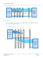
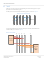
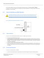
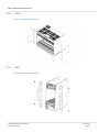
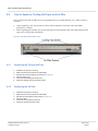
1
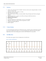
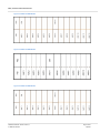
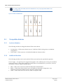
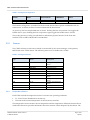
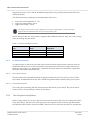
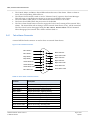
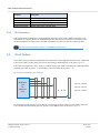
VadaTech VT89x (x = 1, 2, 3, 4, 9) 7U Chassis Series Product Reference Guide September 2014 Version 2.1 VT89x, 7U Chassis Product Reference Guide Copyright © 2014. VadaTech Incorporated, All rights reserved. VadaTech and the globe image are trademarks of VadaTech Incorporated. All other product or service names mentioned in this document are the property of their respective owners. Notice While reasonable efforts have been made to assure the accuracy of this document, VadaTech, Inc. assumes no liability resulting from any omissions in this document or from the use of the information obtained herein. VadaTech reserves the right to revise this document and to make changes periodically and the content hereof without obligation of VadaTech to notify any person of such revision or changes. Electronic versions of this material may be read online, downloaded for personal use, or referenced in another document as a URL to the VadaTech Incorporated Web site. The text itself may not be published commercially in print or electronic form, edited, translated, or otherwise altered without the permission of VadaTech, Inc. It is possible that this publication may contain reference to or information about VadaTech products (machines and programs), programming, or services that are not available in your country. Such references or information must not be construed to mean that VadaTech intends to announce such products, programming, or services in your country. Trademarks The VadaTech, Inc name and logo are registered trademarks of VadaTech Incorporated in the U.S.A. All other product or service names mentioned in this document are the property of their respective owners. ©2014 VadaTech Incorporated. Printed in the U.S.A., All Rights Reserved. VADATECH FORM No. 3WI731-01 Rev. B VT-MAN-CUS-100146 Page 2 of 38 09/2014 VT89x, 7U Chassis Product Reference Guide Revision History Doc Revision Description of Change Revision Date 1.0 Initial release for VT891 October 2010 2.0 Manual updated with VT892, VT893, VT894 information November 2013 2.1 Manual Updated with VT899 information September 2014 VADATECH FORM No. 3WI731-01 Rev. B VT-MAN-CUS-100146 Page 3 of 38 09/2014 VT89x, 7U Chassis Product Reference Guide Table of Contents 1 INTRODUCTION ............................................................................................................................................. 8 1.1 1.2 1.3 1.3.1 1.3.2 1.4 1.5 2 PURPOSE .............................................................................................................................................................. 8 APPLICABLE PRODUCTS ........................................................................................................................................... 8 DOCUMENT REFERENCES ......................................................................................................................................... 8 Specifications ................................................................................................................................................ 8 Related Documents ....................................................................................................................................... 8 ACRONYMS USED IN THIS DOCUMENT........................................................................................................................ 9 CONVENTIONS USED ............................................................................................................................................ 10 VT89X OVERVIEW .........................................................................................................................................11 2.1 PRODUCT COMPARISON ........................................................................................................................................ 11 2.1.1 Features ...................................................................................................................................................... 13 2.1.2 Custom Options ........................................................................................................................................... 13 2.2 ARCHITECTURE .................................................................................................................................................... 13 2.3 COMPATIBLE MODULES ........................................................................................................................................ 15 2.3.1 Inclusive Modules ........................................................................................................................................ 15 2.3.2 Additional Modules ..................................................................................................................................... 15 3 FUNCTIONAL DESCRIPTION ...........................................................................................................................16 3.1 3.1.1 3.2 3.2.1 3.2.2 3.3 3.3.1 3.3.2 3.4 3.4.1 3.4.2 3.5 3.6 3.6.1 3.6.2 3.6.3 3.6.4 4 FRONT PANEL...................................................................................................................................................... 16 LEDs ............................................................................................................................................................. 16 COOLING UNITS ................................................................................................................................................... 16 Sensors ........................................................................................................................................................ 17 Telco Support and Failover .......................................................................................................................... 18 JTAG SWITCH MODULE (JSM) .............................................................................................................................. 19 JSM Switches ............................................................................................................................................... 19 JSM LEDs ..................................................................................................................................................... 19 TELCO ALARM INTERFACE ...................................................................................................................................... 20 Telco Alarm Connector ................................................................................................................................ 21 FRU Information .......................................................................................................................................... 22 CLOCK OPTIONS .................................................................................................................................................. 22 BACKPLANE TOPOLOGY ......................................................................................................................................... 23 IPMB Bus ..................................................................................................................................................... 23 Fabric A ....................................................................................................................................................... 24 Fabric B ....................................................................................................................................................... 25 Fabrics D to G .............................................................................................................................................. 26 USING THE VT89X .........................................................................................................................................27 4.1 4.2 4.2.1 4.2.2 4.3 4.3.1 4.3.2 4.3.3 4.4 4.4.1 CARRIER NUMBER CONFIGURATION ........................................................................................................................ 27 HOW TO ADD/REMOVE AMC MODULES ................................................................................................................. 29 Insert a Module ........................................................................................................................................... 29 Removing the Module ................................................................................................................................. 29 ADD/REMOVE 19” MOUNTING BRACKETS ............................................................................................................... 30 VT891/VT893 and VT894 ............................................................................................................................ 30 VT892 .......................................................................................................................................................... 31 VT899 .......................................................................................................................................................... 31 HOW TO REPLACE COOLING UNIT TRAYS AND AIR FILTER ............................................................................................ 32 Replacing the Cooling Unit Tray .................................................................................................................. 32 VADATECH FORM No. 3WI731-01 Rev. B VT-MAN-CUS-100146 Page 4 of 38 09/2014 VT89x, 7U Chassis Product Reference Guide 4.4.2 5 5.1 5.2 5.3 Replacing the Air Filter ................................................................................................................................ 32 MODEL SPECIFIC VARIATIONS .......................................................................................................................33 VT893 .............................................................................................................................................................. 33 VT894 .............................................................................................................................................................. 34 VT899 .............................................................................................................................................................. 35 CONTACT VADATECH ...........................................................................................................................................38 TECHNICAL SUPPORT ........................................................................................................................................................ 38 LOCATIONS ..................................................................................................................................................................... 38 VADATECH FORM No. 3WI731-01 Rev. B VT-MAN-CUS-100146 Page 5 of 38 09/2014 VT89x, 7U Chassis Product Reference Guide Figures Figure 1: VT891 Slots Distribution .............................................................................................................................. 13 Figure 2: VT892 Slot Distribution ................................................................................................................................ 14 Figure 3: VT893 Slot Distribution ................................................................................................................................ 14 Figure 4: VT894 Slot Distribution ................................................................................................................................ 14 Figure 5: VT899 Slot Distribution ................................................................................................................................ 15 Figure 6: Vadatech JSM - UTC008 ............................................................................................................................... 19 Figure 7: Telco Alarm Connector ................................................................................................................................ 21 Figure 8: Non-redundant Clock Topology ................................................................................................................... 22 Figure 9: Redundant Clock Topology .......................................................................................................................... 23 Figure 10: IPMB Topology ........................................................................................................................................... 24 Figure 11: Fabric A Topology ....................................................................................................................................... 24 Figure 12: Ports 2 to 3 Direct Connections ................................................................................................................. 25 Figure 13: Fabric B Topology ....................................................................................................................................... 25 Figure 14: Fabrics D to G Topology ............................................................................................................................. 26 Figure 15: Chassis Locator Switch ............................................................................................................................... 27 Figure 16: DA201 Chassis Locator Switch ................................................................................................................... 28 Figure 17: AMC Hot-swap/Extractor Handle – Side View ........................................................................................... 29 Figure 18: VT891 Mounting Brackets .......................................................................................................................... 30 Figure 19: VT892 Mounting Brackets .......................................................................................................................... 31 Figure 20: VT899 Mounting Brackets .......................................................................................................................... 31 Figure 21: CU Tray and Air Filter Screws ..................................................................................................................... 32 Figure 22: VT893 Ports 2-3 Direct Connecitons .......................................................................................................... 33 Figure 23: VT894 Ports 12-15 and Ports 17-20 Routing .............................................................................................. 34 Figure 24: VT899 Ports 12-15 and Ports 17-20 .......................................................................................................... 35 Figure 26: VT899 Backplane Topology ........................................................................................................................ 36 VADATECH FORM No. 3WI731-01 Rev. B VT-MAN-CUS-100146 Page 6 of 38 09/2014 VT89x, 7U Chassis Product Reference Guide Tables Table 1: Acronyms......................................................................................................................................................... 9 Table 2: Product Comparison 1 ................................................................................................................................... 11 Table 3: Product Comparison 2 ................................................................................................................................... 12 Table 4: IPMI LEDs ....................................................................................................................................................... 16 Table 5: Cooling Unit Configuration ............................................................................................................................ 17 Table 6: Cooling Unit Sensors ..................................................................................................................................... 17 Table 7: Cooling Unit Additional Sensors .................................................................................................................... 18 Table 8: JSM Slave Select LEDs .................................................................................................................................... 20 Table 9: JSM Master Select ......................................................................................................................................... 20 Table 10: Telco Alarm Connector Pinouts ................................................................................................................... 21 Table 11: Carrier Number Configuration Reference ................................................................................................... 28 VADATECH FORM No. 3WI731-01 Rev. B VT-MAN-CUS-100146 Page 7 of 38 09/2014 VT89x, 7U Chassis Product Reference Guide 1 Introduction 1.1 Purpose This document describes the VT89x series of chassis based on the MicroTCA specifications. The VT89x series chassis can be used to build fully redundant MicroTCA systems. The main document describes features generic to all chassis in the series, device specific features are described in Model Specific section. 1.2 Applicable Products VT891 VT892 VT893 VT894 VT899 1.3 Document References 1.3.1 Specifications The VT89X is compliant with the following specifications: PICMG® 3.0 R3.0 AdvancedTCA Base Specification PICMG® AMC.0 R2.0 Advanced Mezzanine Card Base Specification PICMG® µTCA.0 R1.0 Core Specification Some of the VT89x products are compliant to other AMC specifications, see Product Comparison for more details. 1.3.2 Related Documents The following documents provide information related to VT89x: Datasheet for your device VadaTech MicroTCA MCH Getting Started Guide VadaTech MicroTCA Shelf Command Line Interface Reference Manual VadaTech MicroTCA Carrier Command Line Interface Reference Manual VadaTech MicroTCA Management Interface Specification VadaTech MicroTCA Carrier SNMP Interface Reference Manual VadaTech MicroTCA Shelf SNMP Interface Reference Manual VADATECH FORM No. 3WI731-01 Rev. B VT-MAN-CUS-100146 Page 8 of 38 09/2014 VT89x, 7U Chassis Product Reference Guide 1.4 VadaTech MicroTCA PM Command Line Interface Reference Manual Acronyms Used in this Document Table 1: Acronyms Acronym Description AMC ATCA BSP CPU DDR DIP ECC EMMC FRU GB GbE GHz GND IPMB IPMI JTAG JSM LED MHz MicroTCA or µTCA MMC PCIe PICMG PrAMC SCP SSH SDR SerDes USB XAUI Advanced Mezzanine Card Advanced Telecommunication Computing Architecture Board Support Package Central Processing Unit Double Data Rate Dual In-line Package Error Correction Coding Enhanced Module Management Controller Field Replaceable Unit Gigabyte Gigabit Ethernet Gigahertz Ground Intelligent Platform Management Bus Intelligent Platform Management Interface Joint Test Action Group JTAG Switch Module Light Emitting Diode Megahertz Micro Telecommunications Computing Architecture Module Management Controller Peripheral Component Interconnect Express PCI Industrial Computer Manufacturers Group Processor Advanced Mezzanine Card Secure Copy Protocol/Program Secure Shell Protocol Sensor Data Record Serializer-Deserializer Universal Serial Bus 10 Gigabit Media Independent Interface VADATECH FORM No. 3WI731-01 Rev. B VT-MAN-CUS-100146 Page 9 of 38 09/2014 VT89x, 7U Chassis Product Reference Guide 1.5 Conventions Used The following conventions are used in this document: Important information, when ignored can cause serious damage to the user or the device is described using this symbol Important information useful to the reader is described next to this symbol VADATECH FORM No. 3WI731-01 Rev. B VT-MAN-CUS-100146 Page 10 of 38 09/2014 VT89x, 7U Chassis Product Reference Guide 2 VT89x Overview The VT89x series are 19” x 7U x 10.5” deep (12” deep with handles) MicroTCA chassis offering various options for shelves, MCH AMC, power modules and cooling types. The VT89x series supports up to 12 AMCs and all the models supports full redundancy with dual MCH, dual power modules and dual cooling unit options (on VT899 only dual cooling units are available). 2.1 Product Comparison Table 2 provides a comparison for various features of the VT89x series. Table 2: Product Comparison 1 Features VT891 VT892 VT893 VT894 AMC Slots MCH Slots PM Slots Cooling Type Power Specifications Full Redundancy (Dual MCHs, PMs, Intelligent CUs) Ports 2-3 Direct Connections Redundant Clocks JSM 12 Full-size 2 2 Front to back 1000 W power supply AMC.1, .2, .3, .4 Yes 12 Full-size 2 2 Bottom to top 1000 W power supply AMC.1, .2, .3, .4 Yes 11 Full-size 2 2 Front to back 1000 W power supply AMC.1, .2, .3, .4 Yes 12 Full-size 2 2 Front to Back 1000 W power supply AMC.1, .2, .3, .4 Yes Optional Optional Optional Optional To be purchased separately Yes Fabric Clock on FCLK Telco Clock on TCLKA, TCLKB, TCLKC and TCLKD Optional To be purchased separately Yes Telco/GPS Clock on TCLKA, TCLKB, TCLKC and TCLKD and Fabric Clock on FCLK Optional To be purchased separately Yes Fabric Clock on FCLK Telco Clock on TCLKA, TCLKB, TCLKC and TCLKD Telco Alarm Others VADATECH FORM No. 3WI731-01 Rev. B VT-MAN-CUS-100146 Optional To be purchased separately Yes Fabric clock to each AMC Page 11 of 38 09/2014 VT89x, 7U Chassis Product Reference Guide Table 3: Product Comparison 2 Features VT899 AMC Slots 6 Full-size, modules or 3 Full-size, double modules 1 1 Front to Back 500 W power supply AMC.1, .2, .3, .4 Redundant Cooling Units only MCH Slots PM Slots Cooling Type Power Specifications Full Redundancy (Dual MCHs, PMs, Intelligent CUs) Ports 2-3 Direct Connections Redundant Clocks JSM Telco Alarm Others VADATECH FORM No. 3WI731-01 Rev. B VT-MAN-CUS-100146 Optional Optional Optional Yes Fabric clock to each AMC Page 12 of 38 09/2014 VT89x, 7U Chassis Product Reference Guide 2.1.1 Features 2.1.2 Clocks: CLK1, CLK2 and CLK3 available to each slots. CLK3 can be configured either as a Fabric clock or as a Telco clock. 1000 W AC supply option (500 W on VT899) Radial I2C bus to each AMC High speed routing on 34 layers with back drilled routing for higher performance and signal integrity High speed MicroTCA connectors (12.5 GHz), allowing for 40G fabric interfaces Redundant FRU information Redundant carrier locator Telco Alarms No active components on the backplane for ease of serviceability ESD jack on front side of chassis, location dependant on model. JTAG Switch Module (JSM) slot RoHS compliant Custom Options You can customize the VT89x such as temperature range, conformal coating, management software type, inclusive JSM and telco alarms, etc. To select the appropriate product to meet your specific requirements, refer to the ordering options section of the datasheet for your product. 2.2 Architecture The VT89x series supports various configurations of module slots. Figure 1: VT891 Slots Distribution VADATECH FORM No. 3WI731-01 Rev. B VT-MAN-CUS-100146 Page 13 of 38 09/2014 VT89x, 7U Chassis Product Reference Guide Figure 2: VT892 Slot Distribution Figure 3: VT893 Slot Distribution Figure 4: VT894 Slot Distribution VADATECH FORM No. 3WI731-01 Rev. B VT-MAN-CUS-100146 Page 14 of 38 09/2014 VT89x, 7U Chassis Product Reference Guide For VT891, VT892 and VT894, when the JSM module is used, only single width AMC can be used in AMC slot 1 Figure 5: VT899 Slot Distribution 2.3 Compatible Modules 2.3.1 Inclusive Modules The following modules are shipped with the VT89x series chassis. 2.3.2 Cooling Units – VT89x series chassis uses two VadaTech VT095 cooling units, in redundant configuration. Telco Alarm – VT89x series use a VadaTech DA200 telco alarm modules Additional Modules The following modules can be used with the VT89x series and must be purchased separately. Power supply – An optional power supply that supplies –48 V, 1000 W power to the power modules can be used with a VT89x chassis, 500W for VT899. Refer to the datasheet for your device, for more information on power supply ordering option. JSM – VT89x series can be used with UTC008 JTAG Switch Modules. MCH – VT89x series chassis allows up to two MCHs, in redundant configuration. Any VadaTech or third party MCHs can be used with a VT89x chassis. AMC – VT89x series will work with any AMC 0 compliant AMC VADATECH FORM No. 3WI731-01 Rev. B VT-MAN-CUS-100146 Page 15 of 38 09/2014 VT89x, 7U Chassis Product Reference Guide 3 Functional Description 3.1 Front Panel 3.1.1 LEDs 3.1.1.1 IPMI LEDs The IPMI LEDs follow AMC specifications. The colors and meanings of the IPMI LEDs are described in Table 4. The IPMI LEDs are found on all removable Field Replaceable Units (FRU) such as an AMC, Power Module or Cooling Unit. Table 4: IPMI LEDs 3.1.1.2 Name Color Description Hot Swap Blue Fail Red OK Green Upgrade Amber Indicates the hot-swap state, per PICMG 3.1 specification. OFF: Module active ON: OK to remove the module BLINKING: Hot-swap/power transition in progress OFF: No fault ON: Non-recoverable fault, indicates that the IPMC has not detected a good power. BLINKING: Recoverable fault OFF: No payload power ON indicates that the IPMC has enabled power and payload power OK. BLINKING: Payload power OK, but held in reset (e-keying in process or failure) OFF: Normal BLINKING: Firmware, SDR, or FRU upgrade is in progress Other LEDs VT89x series chassis front panel have other LEDs that are provide status information of various ports and sub-modules of the chassis. These LEDs are labelled on the front panel and selfexplanatory. 3.2 Cooling Units The VT89x series chassis can be used with two VT095 cooling units,( VT899 chassis uses two VT090 Cooling Units.) in redundant configuration. Table 5 provides information about the cooling units used in a VT89x chassis. VADATECH FORM No. 3WI731-01 Rev. B VT-MAN-CUS-100146 Page 16 of 38 09/2014 VT89x, 7U Chassis Product Reference Guide Table 5: Cooling Unit Configuration Position Name Power Channel IPMB Address FRU ID Bottom Top CU1 CU2 3 4 0xA8 0xAA 40 41 The bottom cooling unit is considered as the air intake unit and the top unit considered as the air exhaust unit. A chassis air filter is located underneath the bottom unit. At power-up, the hot swap handle state is closed. Pushing the Hot-swap button once toggles the handle state to open. Pushing the Hot-swap button again toggles the handle state to Closed. The cooling unit tray overlay provide labels to indicate the physical location of the front side modules such as AMCs, MCH and Power Modules. 3.2.1 Sensors The VT095 contains several sensors which are monitored by the carrier manager on the primary MCH used in the VT89x chassis. The following sensors are available with a VT095 . Table 6: Cooling Unit Sensors 3.2.1.1 Type Name Description 0x01 CU T1 0x04 0x04 0x04 0x04 0x04 0x01 FAN1 RPM FAN2 RPM FAN3 RPM FAN4 RPM FAN5 RPM CU T2 0x01 CU T3 0x01 CU T4 0xF2 0xF1 VT89x CU HS VT89x CU IPMB Cooling unit temperature sensor Fan speed sensor Fan speed sensor Fan speed sensor Fan speed sensor Fan speed sensor Fan controller temperature sensor Cooling unit temperature sensor Cooling unit temperature sensor Hot swap handle status IPMB-0 Status Temperature Sensors Each VT095 includes 4 temperature sensors to monitor the operating conditions. T1, T3 and T4 are distributed on the fan tray T2 monitors the internal temperature of the fan motor controller The temperature sensors monitor the air temperature and the temperature difference between the air intake and exhaust air provides information about the amount of heat dissipated by the chassis. The VADATECH FORM No. 3WI731-01 Rev. B VT-MAN-CUS-100146 Page 17 of 38 09/2014 VT89x, 7U Chassis Product Reference Guide temperature sensors T1,T 3 and T4, distributed along the fan trays, indicate the hot and cold zones within the chassis. The default operating conditions for the temperature sensors are: Lower non recoverable limit = –5°C Upper non critical limit = +65°C Upper critical limit = +80°C The default sensor limits can be updated by using the ScorpionWare™ system manager software but the updated values will be cleared on power cycle The CU that provides the Telco function supports these additional sensors: Only one of the cooling units can manage the telco alarm Table 7: Cooling Unit Additional Sensors 3.2.1.2 Type Name Description 0xE2 0xE1 0xD7 0xF4 POWER SWITCH AIR FILTER PS TELCO ACTIVE TELCO ALARM Status of power switch Air filter presence sensor Telco alarm active status Telco alarm status sensor Air Filter Present Sensor An optical sensor on the fan tray located in the bottom slot detects the presence/removal of the air intake filter When there is no filter present the sensor detects this and creates a major alarm event. When the user issues a “get_diagnostics” command, the major alarm event will list the output and the major alarm indicator will turn ON. 3.2.1.3 Telco Active Sensor The telco active sensor determines which cooling unit (when two CU are used) is in control of the telco alarm. A dedicated LED on the Telco Alarm front panel indicates which cooling unit is active. 3.2.1.4 Power Switch Sensor The cooling unit controlling the telco alarm monitors the chassis power switch. The power switch can be used as a soft-shutdown to safely for the chassis. 3.2.2 Telco Support and Failover Either cooling units (CU) can act as the Telco Device for the Carrier, but only one cooling unit will be active telco device. The active CU will respond to Telco requests from the Carrier, and will include the TELCO STATUS sensor record in its SDR. If the active CU is removed, the other CU will become VADATECH FORM No. 3WI731-01 Rev. B VT-MAN-CUS-100146 Page 18 of 38 09/2014 VT89x, 7U Chassis Product Reference Guide active and will act as the Telco Device. The MicroTCA specifications does not cover redundant Telco Devices, so third-party Carrier Managers may not support this failover behavior. 3.3 JTAG Switch Module (JSM) The VT89x chassis that provide an optional JTAG Switch Module (JSM) provides JTAG support to all JTAG-capable Modules in the system. The front connector is a standard 0.1 header which mates to most JTAG modules. There are three arbitrated master ports (2 MCH and one front/rear connector). The secondary ports are auto-detected if they are present. The module provides transparent communication between the Master and a selected secondary port. All co nfiguration modes use an IEEE1149.1 TAP controller. The JTAG can operate with a clock up to 50 MHz. Figure 6: Vadatech JSM - UTC008 3.3.1 JSM Switches 3.3.2 The FTM REQ switch is used to request JTAG master access for the front connector. The CFG switch allows configuration of the JTAG switch to occur through the front connector. The RST switch resets the JTAG switch JSM LEDs The ACT LED indicates that the JSM is active. The Slave Select LEDs indicate which secondary port is selected. If no LEDs are on, no secondary port is selected. Otherwise, add the numbers next to the illuminated LEDs together and use the values shown in Table 8. VADATECH FORM No. 3WI731-01 Rev. B VT-MAN-CUS-100146 Page 19 of 38 09/2014 VT89x, 7U Chassis Product Reference Guide Table 8: JSM Slave Select LEDs Number JTAG Target 1 2 3 4 5 6 7 8 9 10 11 12 13 14 15 AMC 1 AMC 2 AMC3 AMC 4 AMC 6 AMC 7 AMC 8 AMC 9 AMC 10 AMC 11 AMC 12 CU1 CU2 PM1 PM2 The MGNT LEDs indicate which master is currently granted access. If no LEDs are ON, no master has access. Table 9: JSM Master Select LED JTAG Master 0 Front panel or rear connector MCH 1 MCH 2 1 2 The DPDV LED directly indicates the state of the DPDV bit in the Device Configuration Register. For more information on detailed configuration of JSM, refer to the UTC007/8 User Manual. Depending on the chassis model selected, installing a JSM module may limit the use of double width AMC in slot 1. 3.4 Telco Alarm Interface The VT89x chassis that provides an optional Telco Alarm Interface connector is used to relay alarm information to an external alarm device. DA200 is used as a telco interface in the VT89x series. The “Active 1” and “Active 2” LEDs indicate which Cooling Unit is representing the Telco device to the Carrier Manager. Normally, “Active 1” will be on, indicating that the lower CU is active. VADATECH FORM No. 3WI731-01 Rev. B VT-MAN-CUS-100146 Page 20 of 38 09/2014 VT89x, 7U Chassis Product Reference Guide 3.4.1 The Critical, Major, and Minor Alarm LEDs indicate the state of the alarms. When an alarm is active, the corresponding LED will be on. The Chassis Power Switch is used to send a “Chassis Control” request to the Carrier Manager. This will cause a controlled power-down (or power-up) of all FRUs in the Carrier. The Power Button LED (red) is on when the Chassis Power Switch is set to OFF. The Power Good LED reflects the power state of the DA200. The Telco Alarm Cutoff button is used to engage the Telco Cutoff, turning off the external Telco alarms. The alarm LEDs will not change, but the external alarm device, if any, will be turned off. The Telco Cutoff can be disengaged using the Set Telco Alarm State ATCA Command. When disengaged, the external Telco alarms will turn back on. Telco Alarm Connector A micro DSUB-15 male connector is used to drive an external alarm device. Figure 7: Telco Alarm Connector Minor Reset + Minor Reset Major Reset + Minor Alarm NC Minor Alarm COM Major Alarm NO Major Reset Critical Alarm NO Major Alarm NC Major Alarm COM Critical Alarm NC Power Alarm NO Critical Alarm COM Minor Alarm NO Power Alarm COM Table 10: Telco Alarm Connector Pinouts Pin Name Description Minor Reset + Minor Reset Major Reset + Major Reset Critical Alarm NO Critical Alarm NC Critical Alarm COM Minor Alarm NO Minor Alarm NC Minor Alarm COM Major Alarm NO Minor alarm reset, positive polarity Minor alarm reset, negative polarity Major alarm reset, positive polarity Major alarm reset, negative polarity Critical alarm relay, normally open Critical alarm relay, normally closed Critical alarm relay, common path Minor alarm relay, normally open Minor alarm relay, normally closed Minor alarm relay, common path Major alarm relay, normally open VADATECH FORM No. 3WI731-01 Rev. B VT-MAN-CUS-100146 Page 21 of 38 09/2014 VT89x, 7U Chassis Product Reference Guide 3.4.2 Pin Name Description Major Alarm NC Major Alarm COM Power Alarm NO Power Alarm COM Major alarm relay, normally closed Major alarm relay, common path Power alarm relay, normally open Power alarm relay, common path FRU Information FRU information describes the carrier backplane topology to the chassis MCH controllers. The information is typically held in an EPROM attached to the chassis Telco board or attached to the chassis backplane. In VT89x series, the FRU information is located on the telco alarm module. The Carrier FRU information is stored in the EEPROM at address 0x52 3.5 Clock Options The VT89x series provide non-redundant clock networks connecting MCH clocks CLK1, CLK2 and CLK3 to the AMC clocks CLK1, CLK2 and CLK3 using a dedicated line as shown in Figure 8. CLK3 can be assigned as a Telco clock or a Fabric clock as per AMC.1 specification. Fabric B will be partially provided on ports 1 – 6 and CLK3 is routed to Fabric B on ports 7 – 12. Figure 8: Non-redundant Clock Topology MCH1 CLKs 1,2,3 TO AMC CLKs 1,2,3 MCH CLK1 = AMC CLK1 MCH CLK2 = AMC CLK2 MCH CLK3 = AMC CLK3 AMC 1 AMC 2 AMC 3 AMC 4 AMC n In redundant configuration CLK1 of MCH1 is connected (point-to-point) to each AMC CLK1 and CLK1 of MCH2 is connected (point-to-point) to each AMC CLK3, as shown in Figure 9. VADATECH FORM No. 3WI731-01 Rev. B VT-MAN-CUS-100146 Page 22 of 38 09/2014 VT89x, 7U Chassis Product Reference Guide Figure 9: Redundant Clock Topology AMC 1 AMC 2 AMC 3 AMC 4 AMC n MCH1 CLK1 to AMC CLK1 and MCH CLK2 to AMC CLK2 MCH1 CLK1 to AMC CLK3 and MCH CLK2 to AMC CLK2 (if MCH2 is used) 3.6 Backplane Topology The generic backplane topology, common to VT89x series, is described in this section, see Model Specific for any model specific variations. Depending on the clock options selected, some fabrics may not be routed. 3.6.1 IPMB Bus The VT89x provides a dual-redundant IPMB-0 bus among the MCH1, MCH2, CU1, CU2, PM1, and PM2 modules. The IPMB-L is a radial dual-star with each MCH connected to all AMCs using the I2C bus as shown in Figure 10. VADATECH FORM No. 3WI731-01 Rev. B VT-MAN-CUS-100146 Page 23 of 38 09/2014 VT89x, 7U Chassis Product Reference Guide Figure 10: IPMB Topology MCH2 IPMB TO AMC IPMB (if used) MCH1 IPMB TO AMC IPMB AMC 1 3.6.2 AMC 2 AMC 3 AMC 4 AMC n Fabric A Fabric A from MCH1 is connected to port 0 of each AMC and Fabric A from MCH2 is connected to port 1 of each AMC as shown in Figure 11. Figure 11: Fabric A Topology AMC 1 AMC 2 AMC 3 AMC 4 AMC n MCH1 Fabric A to AMC Port 0 MCH2 Fabric A to AMC Port 1 (if MCH2 is used) VADATECH FORM No. 3WI731-01 Rev. B VT-MAN-CUS-100146 Page 24 of 38 09/2014 VT89x, 7U Chassis Product Reference Guide 3.6.3 Fabric B AMC ports 2 and 3 (SAS / SATA) are routed depending on the selected ordering option. For option (B=1), AMCs are connected directly together. The AMC ports 2 and 3 are interconnected with ordering option B=1, as shown in Figure 12. Figure 12: Ports 2 to 3 Direct Connections 2 3 AMC 1 AMC 2 AMC 3 AMC 4 AMC 5 AMC 6 AMC n For option (B=2), MCH1 Fabric B is connected to AMC port 2 of all AMCs, and MCH2 Fabric B is connected to AMC port 3 as shown in Figure 13. Figure 13: Fabric B Topology AMC 1 AMC 2 AMC 3 AMC 4 AMC n MCH1 Fabric B to AMC Port 2 MCH2 Fabric B to AMC Port 3 (if MCH2 is used) VADATECH FORM No. 3WI731-01 Rev. B VT-MAN-CUS-100146 Page 25 of 38 09/2014 VT89x, 7U Chassis Product Reference Guide Port 2 and 3 configuration is denoted by “B” of the part number, refer to the “Ordering Options” section of the datasheet, for more information. 3.6.4 Fabrics D to G In the fat pipes region, MCH1 Fabrics D, E, F, and G are connected to ports 4, 5, 6, and 7, respectively, on all AMCs. MCH2 Fabrics D, E, F, and G are connected to ports 8, 9, 10, and 11 respectively, on all AMCs as shown in Figure 14. Figure 14: Fabrics D to G Topology AMC 1 AMC 2 AMC 3 AMC 4 AMC n MCH1 Fabrics D-G to AMC Ports 4-7 MCH2 Fabrics D-G to AMC Ports 8-11 (if MCH2 is used) VADATECH FORM No. 3WI731-01 Rev. B VT-MAN-CUS-100146 Page 26 of 38 09/2014 VT89x, 7U Chassis Product Reference Guide 4 Using the VT89x 4.1 Carrier Number Configuration If multiple Carriers are configured with an external Shelf Manager, make sure that each Carrier has a unique Carrier number. The carrier number provides a unique address to each carrier for easy management by shelf/system managers. VT89x chassis use DA200 as the Telco module, except for VT899 as it uses a DA201 module. To set the carrier number, set the Chassis Locator, shown in Figure 15, set the switches on DA200 according to the configuration provided in Table 11. Make sure both the switches are set the same. The Chassis Locator switches are on the top side of the DA200 as shown (in red circle) in Figure 15. Figure 15: Chassis Locator Switch The chassis locator switch on DA201 is shown in Figure 16. VADATECH FORM No. 3WI731-01 Rev. B VT-MAN-CUS-100146 Page 27 of 38 09/2014 VT89x, 7U Chassis Product Reference Guide Figure 16: DA201 Chassis Locator Switch Special attention should be paid whilst removal and re-installation of the telco alarm module, since the edge connectors on the telco alarm module should line up correctly with the backplane. Improper alignment and excessive force could damage the edge connector and also cause serious damage to the chassis backplane Table 11: Carrier Number Configuration Reference Carrier Number Switch 1 Switch 2 Switch 3 Switch 4 1 2 3 4 5 6 7 8 9 10 11 12 13 14 15 16 ON ON ON ON ON ON ON ON OFF OFF OFF OFF OFF OFF OFF OFF ON ON ON ON OFF OFF OFF OFF ON ON ON ON OFF OFF OFF OFF ON ON OFF OFF ON ON OFF OFF ON ON OFF OFF ON ON OFF OFF ON OFF ON OFF ON OFF ON OFF ON OFF ON OFF ON OFF ON OFF VADATECH FORM No. 3WI731-01 Rev. B VT-MAN-CUS-100146 Page 28 of 38 09/2014 VT89x, 7U Chassis Product Reference Guide The Carrier number can also be set through the Carrier Manager CLI set_carrier_number command. The Carrier Number set through the CLI takes precedence over the Carrier number set in the Chassis Locator switch 4.2 How to Add/Remove AMC Modules The module should only be removed from a running carrier when the AMC Blue LED is solid ON. Removing the module before the blue LED is on may cause severe damage to the device. Figure 17: AMC Hot-swap/Extractor Handle – Side View 4.2.1 Insert a Module To insert a new field replaceable module, such as an AMC, into the chassis: 1. 2. 3. 4. 4.2.2 Pull out the hot-swap handle until it stops Insert the module into the chassis guide rails making sure the hot swap handle is towards the lower side of the chassis (chassis with vertical slots only) and push the front panel firmly until it is fully seated into the connector. If the card does not go fully in, do not force it and instead remove it and check for proper orientation or obstructions. Once fully inserted the Blue LED should go to solid ON. Push in the handle to latch the module into the chassis, the Blue LED should blink for a short duration and then goes to solid OFF and the green LED would be expected to be solid ON to indicate that the payload power was applied. Removing the Module To remove a module such as an AMC: 1. Pull out the hot-swap handle until it stops (but do not pull hard enough to remove the module itself yet). VADATECH FORM No. 3WI731-01 Rev. B VT-MAN-CUS-100146 Page 29 of 38 09/2014 VT89x, 7U Chassis Product Reference Guide 2. 3. 4.3 The Blue LED should blink for a short duration and then go solid ON. Once the blue LED is ON, pull the hot-swap handle straight out firmly to remove the module from the chassis Add/Remove 19” Mounting Brackets This section describes how to install 19” mounting brackets for various VT89x chassis . 4.3.1 VT891/VT893 and VT894 Figure 18: VT891 Mounting Brackets VADATECH FORM No. 3WI731-01 Rev. B VT-MAN-CUS-100146 Page 30 of 38 09/2014 VT89x, 7U Chassis Product Reference Guide 4.3.2 VT892 Figure 19: VT892 Mounting Brackets 4.3.3 VT899 Figure 20: VT899 Mounting Brackets VADATECH FORM No. 3WI731-01 Rev. B VT-MAN-CUS-100146 Page 31 of 38 09/2014 VT89x, 7U Chassis Product Reference Guide 4.4 How to Replace Cooling Unit Trays and Air Filter The Cooling Units and Air Filter are hot-swappable but it is recommended to do so when system is off since: When replacing a CU, the system's air flow will be reduced or removed and could make payloads to overheat. When replacing the air filter, the system may push in dust particles that will compromise fan life span and overall system cleanliness. Figure 21: CU Tray and Air Filter Screws 4.4.1 Replacing the Cooling Unit Tray 1. 2. 3. 4. 5. 6. 4.4.2 Shutdown the system, if running Make sure power to the device is switched off Remove the screws (orange arrows) shown in Figure 21. Pull the cooling Tray Insert the new cooling unit into the slot Secure the cooling unit trays with the screws Replacing the Air Filter 1. 2. 3. 4. 5. 6. Shutdown the system, if running Make sure power to the device is switched off Remove the screws (blue arrows) shown in Figure 21. Pull the air filter Insert the new air filter into the slot Secure the air filter with the screws VADATECH FORM No. 3WI731-01 Rev. B VT-MAN-CUS-100146 Page 32 of 38 09/2014 VT89x, 7U Chassis Product Reference Guide 5 Model Specific Variations This section provides information specific to the individual chassis of the VT89x series. 5.1 VT893 The VT893 chassis only supports up to 11 AMCs and with the ordering option B=1, the AMC ports 2 and 3 have interconnections as shown in Figure 22. Figure 22: VT893 Ports 2-3 Direct Connecitons 2 2 3 3 AMC 1 AMC 2 VADATECH FORM No. 3WI731-01 Rev. B VT-MAN-CUS-100146 AMC 3 AMC 4 AMC 5 AMC 6 AMC 7 AMC 8 AMC 9 AMC 10 AMC 11 Page 33 of 38 09/2014 VT89x, 7U Chassis Product Reference Guide 5.2 VT894 On the VT894 chassis, the AMC ports 12 to 15 and ports 17 to 20 are interconnected as shown in Figure 23. Figure 23: VT894 Ports 12-15 and Ports 17-20 Routing VADATECH FORM No. 3WI731-01 Rev. B VT-MAN-CUS-100146 Page 34 of 38 09/2014 VT89x, 7U Chassis Product Reference Guide 5.3 VT899 The summary of differences between VT899 and other VT89x chassis are: VT899 only supports single 500 W power supply and single MCH VT899 has two Vadatech VT090 Cooling Units VT899 has Vadatech DA201 Telco Alarm, instead of DA200 VT899 only supports up to 6 full-size, single module AMCs VT899 can be purchased with a JSM installed (see ordering options in VT899 datasheet). When JSM is installed, Slot AMC6 will not support Full-Height modules as the slot bay shared with JSM. The ports 12-15 and ports 17-20 are routed as shown in Figure 24Error! Reference source not found.. Figure 24: VT899 Ports 12-15 and Ports 17-20 AMC Ports 12 12 13 13 14 14 15 15 AMC 1 AMC Ports AMC 2 AMC 3 AMC 4 AMC 5 AMC Ports AMC 6 17 17 18 18 19 19 20 20 AMC Ports VADATECH FORM No. 3WI731-01 Rev. B VT-MAN-CUS-100146 Page 35 of 38 09/2014 VT89x, 7U Chassis Product Reference Guide The VT899 backplane topology is shown in Figure 25. Figure 25: VT899 Backplane Topology AMC 1 AMC 2 AMC 3 AMC 4 AMC 5 AMC 6 MCH IPMB to AMC IPMB MCH Fabric A to AMC Port 0 AMC Ports 2 and 3 Direct Connections (optional) MCH Fabric A to AMC Port1 2 3 MCH Fabric B to AMC Port 2 (optional) MCH Fabric B to AMC Port 3 (optional) MCH Fabrics D-G to AMC Ports 4-7 MCH Fabrics D-G to AMC Ports 8-11 AMC JTAG Signals JSM Slot MCH CLKs 1,2,3 to AMC CLKs 1,2,3 VADATECH FORM No. 3WI731-01 Rev. B VT-MAN-CUS-100146 Page 36 of 38 09/2014 VT89x, 7U Chassis Product Reference Guide Notes VADATECH FORM No. 3WI731-01 Rev. B VT-MAN-CUS-100146 Page 37 of 38 09/2014 VT89x, 7U Chassis Product Reference Guide Contact VadaTech Technical Support If you have purchased the VadaTech product through our distributor network, contact your distributor for any technical assistance. If you require further technical support, you can contact VadaTech technical support team by forwarding your support requests to [email protected]. Locations VadaTech Corporate Office European Sales Office Asia Pacific Sales Office 198 N. Gibson Rd Henderson, NV 89014 USA Email: [email protected] Telephone: +1 702 896 3337 Fax: +1 702 896 0332 Ocean Village Innovation Centre, Ocean Way, Ocean Village, Southampton, SO14 3JZ, UK Email: [email protected] Telephone: +44 2380 381982 Fax: +44 2380 381983 7th Floor, No 2, Wenhu Street, Neihu District, Taipei 114, Taiwan Email: [email protected] Telephone: +886 2 2627 7655 Fax: +886 2 2627 7792 © 2014 VadaTech, Incorporated. All rights reserved The VadaTech logo is a registered trademark of VadaTech, Inc. Other registered trademarks are the property of their respective owners. AdvancedMC™, AdvancedTCA™ and µTCA™ logos are trademarks of the PCI Industrial Computers Manufacturers Group. VADATECH FORM No. 3WI731-01 Rev. B VT-MAN-CUS-100146 Page 38 of 38 09/2014


![VadaTech VT85x User Manual[1]](http://vs1.manualzilla.com/store/data/005803212_1-bb50408d9ec4263de47f5dcd2a97e7b3-150x150.png)