1
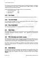
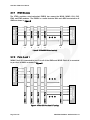
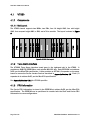
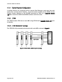
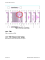
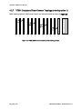
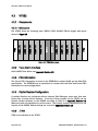
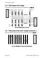
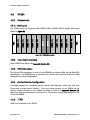
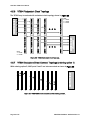
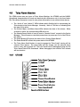
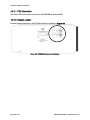
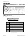
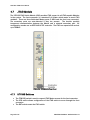
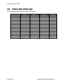
VadaTech VT86x (0,1,2,3,4 series) User Manual August 6, 2010 Version 1.0 THE POWER OF VISION VadaTech VT86x User Manual Copyright © 2010 VadaTech Incorporated All rights reserved VadaTech and the globe image are trademarks of VadaTech Incorporated. All other product or service names mentioned in this document are the property of their respective owners. Notice While reasonable efforts have been made to assure the accuracy of this document, VadaTech, Inc. assumes no liability resulting from any omissions in this document or from the use of the information obtained herein. VadaTech reserves the right to revise this document and to make changes periodically and the content hereof without obligation of VadaTech to notify any person of such revision or changes. Electronic versions of this material may be read online, downloaded for personal use, or referenced in another document as a URL to the VadaTech Incorporated Web site. The text itself may not be published commercially in print or electronic form, edited, translated, or otherwise altered without the permission of VadaTech, Inc. It is possible that this publication may contain reference to or information about VadaTech products (machines and programs), programming, or services that are not available in your country. Such references or information must not be construed to mean that VadaTech intends to announce such products, programming, or services in your country. Trademarks The VadaTech, Inc name and logo are registered trademarks of VadaTech Incorporated in the U.S.A. All other product or service names mentioned in this document are the property of their respective owners. © 2010, VadaTech Incorporated. Printed in the U.S.A., All Rights Reserved. Page 2 of 37 VADATECH FORM No. 3WI731-01 Rev. B VadaTech VT86x User Manual Revision History Doc Rev 1.0 Page 3 of 37 Description of Change Document Created Revision Date 08/06/2010 VADATECH FORM No. 3WI731-01 Rev. B VadaTech VT86x User Manual Table of Contents 1 Overview ...................................................................................................................................... 8 1.1 Document References ...................................................................................................... 9 1.2 Acronyms Used in this Document................................................................................... 9 2 Components.............................................................................................................................. 10 2.1 Power Supply.................................................................................................................... 10 2.2 VT095 Cooling Units........................................................................................................ 10 2.3 Chassis Sensors ............................................................................................................... 10 2.3.1 Temperature ............................................................................................................ 10 2.3.2 Filter Present............................................................................................................ 11 2.3.3 Telco Active Sensor................................................................................................. 11 2.3.4 Power Switch Sensor .............................................................................................. 11 2.4 Telco Alarm....................................................................................................................... 11 2.5 FRU Information and Carrier Locator ........................................................................... 11 2.6 Clock Options ................................................................................................................... 11 2.7 Backplane Topology ........................................................................................................ 12 2.7.1 IPMB Busses ............................................................................................................ 13 2.7.2 Ports 0 and 1 ........................................................................................................... 13 2.7.3 Ports 2 and 3 ........................................................................................................... 14 2.7.4 Ports 4 – 7 and 8 – 11 ........................................................................................... 15 3 Physical Description ................................................................................................................ 16 3.1 Front Panel ....................................................................................................................... 16 3.1.1 Telco Interface ......................................................................................................... 16 3.1.2 Telco Support and Failover .................................................................................... 16 4 Appendices ............................................................................................................................... 18 4.1 VT860 ................................................................................................................................ 19 4.1.1 Components............................................................................................................. 19 4.1.1.1 Slot Layout ....................................................................................................... 19 4.1.2 Telco Alarm Interface ............................................................................................. 19 4.1.3 FRU Information ...................................................................................................... 19 4.1.4 Carrier Number Configuration ............................................................................... 20 4.1.5 JTAG...........................................................................................................................20 4.1.5.1 JTAG Backplane Topology.............................................................................. 20 4.1.6 VT860 Redundant Clock Topology ....................................................................... 21 4.1.7 VT860 Backplane Direct Connect Topology (ordering option 1)...................... 21 4.2 VT861 ................................................................................................................................ 22 4.2.1 Components............................................................................................................. 22 4.2.1.1 Slot Layout ....................................................................................................... 22 4.2.2 Telco Alarm Interface ............................................................................................. 22 4.2.3 FRU Information ...................................................................................................... 22 4.2.4 Carrier Number Configuration ............................................................................... 22 4.2.5 JTAG...........................................................................................................................23 4.2.6 VT861 Redundant Clock Topology ....................................................................... 23 Page 4 of 37 VADATECH FORM No. 3WI731-01 Rev. B VadaTech VT86x User Manual 4.2.7 VT861 Backplane Direct Connect Topology (ordering option 1)...................... 24 4.3 VT862 ................................................................................................................................ 25 4.3.1 Components............................................................................................................. 25 4.3.1.1 Slot Layout ....................................................................................................... 25 4.3.2 Telco Alarm Interface ............................................................................................. 25 4.3.3 FRU Information ...................................................................................................... 25 4.3.4 Carrier Number Configuration ............................................................................... 25 4.3.5 JTAG...........................................................................................................................25 4.3.6 VT862 Redundant Clock Topology ....................................................................... 26 4.3.7 VT862 Backplane Direct Connect Topology (ordering option 1)...................... 26 4.4 VT863 ................................................................................................................................ 27 4.4.1 Components............................................................................................................. 27 4.4.1.1 Slot Layout ....................................................................................................... 27 4.4.2 Telco Alarm Interface ............................................................................................. 27 4.4.3 FRU Information ...................................................................................................... 27 4.4.4 Carrier Number Configuration ............................................................................... 27 4.4.5 JTAG...........................................................................................................................27 4.4.6 VT863 Redundant Clock Topology ....................................................................... 28 4.4.7 VT863 Backplane Direct Connect Topology (ordering option 1)...................... 28 4.5 VT864 ................................................................................................................................ 29 4.5.1 Components............................................................................................................. 29 4.5.1.1 Slot Layout ....................................................................................................... 29 4.5.2 Telco Alarm Interface ............................................................................................. 29 FRU Information ...................................................................................................... 29 4.5.3 4.5.4 Carrier Number Configuration ............................................................................... 29 4.5.5 JTAG...........................................................................................................................29 4.5.6 VT864 Redundant Clock Topology ....................................................................... 30 4.5.7 VT864 Backplane Direct Connect Topology (ordering option 1)...................... 30 4.6 Telco Alarm Modules ...................................................................................................... 31 4.6.1 UTC009 ..................................................................................................................... 31 4.6.1.1 FRU Information.............................................................................................. 32 4.6.1.2 Chassis Locator ............................................................................................... 32 4.6.2 DA200 ....................................................................................................................... 33 4.6.2.1 FRU Information.............................................................................................. 33 4.6.2.2 Chassis Locator ............................................................................................... 34 4.6.3 Telco Alarm Connector ........................................................................................... 34 4.7 JTAG Module..................................................................................................................... 35 4.7.1 UTC008 Switches .................................................................................................... 35 4.7.2 UTC008 LEDs ........................................................................................................... 36 4.8 Carrier Locator Switch Logic .......................................................................................... 37 Page 5 of 37 VADATECH FORM No. 3WI731-01 Rev. B VadaTech VT86x User Manual Figures Figure 2: VT86x non-redundant clock topology, CLK3 can run as Fabric Clock (e.g. PCIe clock). ................................................................................................................................................. 12 Figure 3: VT86x AMC I2C bus topology........................................................................................ 13 Figure 4: VT86x AMC Port 0 and 1 Topology. ............................................................................. 13 Figure 5: VT86x AMC Port 2 and 3 Topology with Ordering Option 2. .................................... 14 Figure 6: VT86x AMC Ports 4-7 Topology with Ordering Option 2. .......................................... 15 Figure 7: VT095 Front Panel.......................................................................................................... 16 Figure 8: VT860 Slot Layout. ......................................................................................................... 19 Figure 9: VT860 JTAG to AMC backplane topology.................................................................... 20 Figure 10: VT860 Redundant Clock Topology. ........................................................................... 21 Figure 11: VT860 AMC direct connections with ordering option 1.......................................... 21 Figure 12: VT861 Slot Layout........................................................................................................ 22 Figure 13: VT861 Chassis Locator Switches............................................................................... 23 Figure 14: VT861 AMC direct connections with ordering option 1.......................................... 24 Figure 15: VT862 Slot Layout........................................................................................................ 25 Figure 16: VT862 Redundant Clock Topology. ........................................................................... 26 Figure 17: VT862 AMC direct connections with ordering option 1.......................................... 26 Figure 18: VT861 Slot Layout........................................................................................................ 27 Figure 19: VT863 Redundant Clock Topology. ........................................................................... 28 Figure 20: VT863 AMC direct connections with ordering option 1.......................................... 28 Figure 21: VT864 Slot Layout........................................................................................................ 29 Figure 22: VT864 Redundant Clock Topology. ........................................................................... 30 Figure 23: VT864 AMC direct connections with ordering option 1.......................................... 30 Figure 24: UTC009 Front Panel..................................................................................................... 31 Figure 25: UTC009 Chassis Locator Switches. ........................................................................... 32 Figure 26: DA200 Front Panel. ..................................................................................................... 33 Figure 27: DA200 Chassis Locator Switches.............................................................................. 34 Figure 28: Telco Alarm Connector ................................................................................................. 34 Figure 29: UTC008 JSM Front Panel ............................................................................................ 35 Page 6 of 37 VADATECH FORM No. 3WI731-01 Rev. B VadaTech VT86x User Manual Tables Table 1: Model Comparison Chart .................................................................................................. 8 Table 2: Acronyms............................................................................................................................. 9 Table 3: Cooling Units ..................................................................................................................... 10 Table 4: VT095 LEDs....................................................................................................................... 16 Table 5: Telco Connector Pins ........................................................................................................ 34 Table 6: Slave Select LEDs ............................................................................................................ 36 Table 7: MGNT LEDs........................................................................................................................ 36 Table 8: Carrier Number Configuration........................................................................................ 37 Page 7 of 37 VADATECH FORM No. 3WI731-01 Rev. B VadaTech VT860 User Manual 1 Overview Figure 1: Typical VT86x Chassis. The VT86x series, shown in Figure 1, are 5U MicroTCA carriers offering a variety of chassis, AMC and MCH combinatorial options. Current production comprises VT86x models x=[0 1 2 3 4]. This document describes the common VT86x chassis, configuration and operation. Attached Appendices describe each model’s individual characteristics with configuration and operational characteristics. Table 1 provides shows a comparison chart for each model’s features. Model # of MCH Slots VT860 VT861 VT862 VT863 VT864 2 1 2 2 2 # of Power Module slots 2 1 2 2 2 JSM slot Telco Alarm Yes No No No No Yes No Yes Yes Yes # of AMC FH Slots 4 12 10 6 10 # of AMC MH Slots 6 0 0 6 0 # of AMC CH Slots 2 0 0 0 0 Dual Redundant Fan Tray 1000W Power Supply Yes Yes Yes Yes Yes Yes Yes Yes Yes Yes Table 1: Model Comparison Chart Page 8 of 37 VADATECH FORM No. 3WI731-01 Rev. B VadaTech VT86x User Manual 1.1 1.2 Document References PICMG Specification MTCA.0 R1.0 (MicroTCA) VadaTech VT860 data sheet VadaTech VT861 data sheet VadaTech VT862 data sheet VadaTech VT863 data sheet VadaTech VT864 data sheet Acronyms Used in this Document Acronym AMC CU JTAG MCH PM FH MH CH Description Advanced Mezzanine Card Cooling Unit Joint Test Action Group MicroTCA Carrier Hub Power Module Full Height Mid Height Compact Height Table 2: Acronyms Page 9 of 37 VADATECH FORM No. 3WI731-01 Rev. B VadaTech VT86x User Manual 2 Components The VT86x carrier’s components include an optional 1000W AC power supply, two Cooling Units, temp sensors, a removable JTAG Switch Module (JSM), and a removable Telco Alarm Interface board. The removable Telco Alarm Boards contain the Carrier Locator and Carrier FRU Information devices. 2.1 Power Supply The optional power supply supplies 1000W, 48V power to the chassis Power Module(s). 2.2 VT095 Cooling Units The VT860 carrier includes two redundant VT095 MicroTCA Cooling Units (CUs), as shown in the following table. Position Bottom Top CU1 CU2 Name Power Channel 3 4 IPMB Address 0xA8 0xAA 40 41 FRU ID Table 3: Cooling Units The bottom unit is considered the intake air unit and the top unit considered the exhaust air unit. A chassis air filter is located underneath the bottom unit. 2.3 Chassis Sensors Chassis sensors available on the VT86x series are monitored by the Carrier Manager running on an MCH. The sensors available are as follows: 2.3.1 Temperature Temperature sensors are incorporated in the VT095 Cooling Units to monitor operating conditions. Each VT095 contains 4 temp sensors for: 1. 2. 3. 4. TEMP1 – distributed on fan tray TEMP2 – monitors fan motor controller internal temps TEMP3 – distributed on fan tray TEMP4 – distributed on fan tray Page 10 of 37 VADATECH FORM No. 3WI731-01 Rev. B VadaTech VT86x User Manual The temperature sensor differential between intake and exhaust air provides an indication of heat dissipation for the chassis. Distributed sensors TEMP1, TEMP3, and TEMP4 indicate hot/cool zones within the chassis. VadaTech MCH software sets operating conditions for the temp sensors: Lower Non Recoverable -5 C Upper Non Critical 65 C Upper Critical 80 C 2.3.2 Filter Present A sensor on the lower Cooling Unit detects the absence/presence of the intake air filter. 2.3.3 Telco Active Sensor One Cooling Unit manages the Telco Alarm and the Telco Active Sensor is used to determine which Cooling Unit is in control. 2.3.4 Power Switch Sensor The Cooling Unit controlling the Telco Alarm monitors the Chassis Power Switch. 2.4 Telco Alarm Most VT86x chassis offer Telco alarm functionality to provide the end user with information concerning operational anomalies detected. (See Appendix for model-specific information.) 2.5 FRU Information and Carrier Locator FRU information describes the carrier backplane topology to the chassis MCH controllers. The information is typically held in an EPROM attached to the chassis Telco board or attached to the chassis backplane. (See Appendix for model-specific information.) The Carrier Locator can be assigned via mechanical dip switches located on the Telco board or the chassis backplane. (See Appendix for model-specific information and switch settings Table.) 2.6 Clock Options The VT86x series provide non-redundant clock networks connecting MCH clocks CLK1, CLK2 and CLK3 to the AMC clocks CLK1, CLK2 and CLK3 by a dedicated line (Shown in Figure 2). CLK3 can be assigned a Telco clock or become the Fabric clock per AMC.1 Page 11 of 37 VADATECH FORM No. 3WI731-01 Rev. B VadaTech VT86x User Manual specification. Fabric B will be partially provided on ports 1 – 6 and CLK6 is routed to Fabric B on ports 1 – 12. a 2.7 n AMC CLK1, 2 and 3 4 AMC CLK1, 2 and 3 3 AMC CLK1, 2 and 3 2 AMC CLK1, 2 and 3 1 AMC CLK1, 2 and 3 MCH1 CLK1, 2 and 3 Redundant options connect CLK1 of MCH1 point-to-point to each AMC CLK1 and CLK1 of MCH2 point-to-point to each AMC CLK3. (See Appendix for model-specific redundant clock information.) AMC AMC AMC AMC AMC 1 n 2 3 4 Figure 2: VT86x non-redundant clock topology, CLK3 can run as Fabric Clock (e.g. PCIe clock). Backplane Topology Common VT86x backplane connectivity is shown here. Check model-specific information in Appendix. Depending on the clock options selected, some fabrics may not be routed. Refer to the VT86x data sheet for details. Page 12 of 37 VADATECH FORM No. 3WI731-01 Rev. B VadaTech VT86x User Manual 2.7.1 IPMB Busses 4 n 3 4 MCH2 IPMB (If present) 3 AMC IPMB 2 AMC IPMB 2 AMC IPMB 1 AMC IPMB 1 AMC IPMB MCH1 IPMB The VT86x provides a dual-redundant IPMB-0 bus among the MCH1, MCH2, CU1, CU2, PM1, and PM2 modules. The IPMB-L is a radial dual-star with each MCH connected to all AMCs as shown in Figure 3. n AMC 1 AMC 2 AMC 3 AMC 4 AMC n Figure 3: VT86x AMC I2C bus topology. 2.7.2 Ports 0 and 1 MCH1 Fabric A is connected to port 0 on all of the AMCs and MCH2 Fabric A is connected to port 1 on all AMCs as shown in Figure 4. Port 0 Port 0 4 Port 0 3 Port 0 2 Port 0 MCH1 Fabric A 1 n Port 1 Port 1 Port 1 Port 1 Port 1 AMC1 AMC2 AMC3 AMC4 AMCn 2 3 4 n MCH2 Fabric A (If present) 1 Figure 4: VT86x AMC Port 0 and 1 Topology. Page 13 of 37 VADATECH FORM No. 3WI731-01 Rev. B VadaTech VT86x User Manual 2.7.3 Ports 2 and 3 AMC ports 2 and 3 (SAS / SATA) are routed depending on the ordering option. Under option 1, AMCs are connected directly together (See Appendix for model-specific information). Under option 2, MCH1 Fabric B is connected to port 2 on all of the AMCs, and MCH2 Fabric B is connected to port 3 on all of the AMCs as shown in Figure 5. Port 2 Port 2 4 Port 2 3 Port 2 2 Port 2 MCH1 Fabric A 1 n Port 3 Port 3 Port 3 Port 3 Port 3 AMC1 AMC2 AMC3 AMC4 AMCn 2 3 4 n MCH2 Fabric A (If present) 1 Figure 5: VT86x AMC Port 2 and 3 Topology with Ordering Option 2. Page 14 of 37 VADATECH FORM No. 3WI731-01 Rev. B VadaTech VT86x User Manual 2.7.4 Ports 4 – 7 and 8 – 11 In the fat pipes region, MCH1 Fabrics D, E, F, and G are connected to ports 4, 5, 6, and 7, respectively, on all AMCs. MCH2 Fabric D, E, F, and G are connected to ports 8, 9, 10, and 11, respectively, on all AMCs as shown in Figure 6. Ports 4-7 Ports 4-7 4 Ports 4-7 3 Ports 4-7 2 Ports 4-7 MCH1 Fabric D - G 1 n Ports 8-11 Ports 8-11 Ports 8-11 Ports 8-11 AMC2 AMC3 AMC4 AMCn 2 3 4 n MCH2 Fabric D - G (If present) Ports 8-11 AMC1 1 Figure 6: VT86x AMC Ports 4-7 Topology with Ordering Option 2. Page 15 of 37 VADATECH FORM No. 3WI731-01 Rev. B VadaTech VT86x User Manual 3 Physical Description 3.1 Front Panel Each VT095 provides four LEDs and a hot swap button, as shown in Figure 7. Figure 7: VT095 Front Panel The VT095 LEDs indicate the state of the CU, as described in the following table. Name Color Hot Swap Blue Fail Red OK Upgrade Green Amber Description indicates hot-swap state, per AMC.0 and MicroTCA specifications ON indicates failure. For example, the geographic address pins are invalid, or payload power has failed. BLINKING indicates that one or more fans have stalled, or are still spinning up. OFF indicates normal operation. ON indicates normal operation. ON while the CU operation is interrupted during a firmware upgrade. Table 4: VT095 LEDs At power-on, the hot swap handle state is Closed. Pushing the Hot Swap button once toggles the handle state to Open. Pushing the Hot Swap button again toggles the handle state to Closed. 3.1.1 Telco Interface Telco alarms are handled per model, see Appendices for model information. 3.1.2 Telco Support and Failover Either CU can act as the Telco Device for the Carrier, but only one CU at a time will do so. The active CU will respond to Telco requests from the Carrier, and will include the TELCO STATUS sensor record in its SDR. If the active CU is removed, the other CU will become active and will act as the Telco Device. The MicroTCA specification does not cover Page 16 of 37 VADATECH FORM No. 3WI731-01 Rev. B VadaTech VT86x User Manual redundant Telco Devices, so third-party Carrier Managers may not support this failover behavior. Page 17 of 37 VADATECH FORM No. 3WI731-01 Rev. B VadaTech VT86x User Manual 4 Appendices The Appendices contain model-specific information for each product followed by configuration information and tables. Appendix 4.1– Model VT860 Appendix 4.2 – Model VT861 Appendix 4.3 – Model VT862 Appendix 4.4 – Model VT863 Appendix 4.5 – Model VT864 Appendix 4.6 – Telco Alarm Chassis Appendix 4.7 – JTAG Module Appendix 4.8 – Carrier Locator Switches Page 18 of 37 VADATECH FORM No. 3WI731-01 Rev. B VadaTech VT86x User Manual 4.1 VT860 4.1.1 Components 4.1.1.1 Slot Layout Telco PM2 AMC12 - FH AMC11 - FH AMC10 - MH AMC9 - MH AMC7 - CH AMC8 - MH MCH2 MCH1 AMC5 - MH AMC6 - CH AMC4 - MH AMC3 - MH AMC2 - FH AMC1 - FH PM1 JSM The VT860 chassis supports two MCHs, two PMs, four full height AMC, four mid height AMC, four compact height AMC, a JSM, and a Telco module. The layout is shown in Figure 8. Figure 8: VT860 Slot Layout. 4.1.2 Telco Alarm Interface The UTC009 Telco Alarm Interface board goes in the rightmost slot in the VT860. It provides an 8KB FRU EEPROM on each private MCH I2C bus. Each EEPROM is at address 0x52, per the MicroTCA specification. It also provides an 8574A I/O expander on the same buses to access the Carrier Locator Devices described in Appendix Section 4.6. Each I/O expander is at address 0x3E, per the MicroTCA specification. See Appendix Section 4.6.1 for UTC009 specifics. 4.1.3 FRU Information The Carrier FRU information is stored in the EEPROM at address 0x52, per the MicroTCA specification. The EEPROM can be partitioned to contain both the Shelf and Carrier FRU Information in some configurations. Page 19 of 37 VADATECH FORM No. 3WI731-01 Rev. B VadaTech VT86x User Manual 4.1.4 Carrier Number Configuration If multiple Carriers are configured with an external Shelf Manager, make sure that each Carrier has a unique Carrier number. To set the Carrier number for the VT860, set the Chassis Locator switches on the UTC009 according to Table 8 in Appendix Section 4.8Make sure both the MCH1 and MCH2 switches are set the same. 4.1.5 JTAG The VT860 enables JTAG bus to each AMC using UTC008 (See Appendix Section 4.71.1.1 for details). 4.1.5.1 JTAG Backplane Topology The UTC008 is fully connected point-to-point with each AMC as shown in Figure 9. AMC JTAG AMC JTAG AMC JTAG AMC JTAG AMC JTAG 2 3 4 n AMC 1 AMC 2 AMC 3 AMC 4 UTC 008 IN JSM SLOT 1 AMC n Figure 9: VT860 JTAG to AMC backplane topology. Page 20 of 37 VADATECH FORM No. 3WI731-01 Rev. B VadaTech VT86x User Manual 4.1.6 VT860 Redundant Clock Topology The VT860 may be ordered with redundant clock topology shown in Figure 10. NOTE: 1 -> 1 2 -> 2 CLK 1 & 2 CLK 1 & 2 4 CLK 1 & 2 3 CLK 1 & 2 2 CLK 1 & 2 MCH1 CLK 1 & 2 1 n CLK 3 & 2 CLK 3 & 2 CLK 3 & 2 CLK 3 & 2 CLK 3 & 2 AMC1 AMC2 AMC3 AMC4 AMCn NOTE: 1 -> 3 2 -> 2 2 3 4 n MCH2 CLK 1 & 2 (If present) 1 Figure 10: VT860 Redundant Clock Topology. 4.1.7 VT860 Backplane Direct Connect Topology (ordering option 1) 2 2 2 2 2 2 3 3 2 2 2 2 2 2 3 Port Port Port Port Port Port Port Port Port Port Port Port 3 AMC 1 AMC 2 AMC 3 AMC 4 AMC 5 AMC 6 AMC 7 AMC 8 AMC 9 AMC 10 AMC 11 AMC 12 AMC PORTS 2 & 3 With ordering option 2, AMC ports 2 and 3 are interconnected as shown in Figure 11. Figure 11: VT860 AMC direct connections with ordering option 1. Page 21 of 37 VADATECH FORM No. 3WI731-01 Rev. B VadaTech VT86x User Manual 4.2 VT861 4.2.1 Components 4.2.1.1 Slot Layout PM1 AMC12 - FH AMC11 - FH AMC10 - FH AMC9 - FH AMC8 - FH AMC7 - FH MCH1 AMC6 - FH AMC5 - FH AMC4 - FH AMC3 - FH AMC2 - FH AMC1 - FH The VT861 offers the following slots: 1-MCH, 1-PM, 12-AMC (FH-full height) with layout shown in Figure 12. Figure 12: VT861 Slot Layout. 4.2.2 Telco Alarm Interface No Telco alarm interface available on model VT861. 4.2.3 FRU Information The Carrier FRU information is stored in the EEPROM at address 0x52, per the MicroTCA specification. The EEPROM can be partitioned to contain both the Shelf and Carrier FRU Information in some configurations. 4.2.4 Carrier Number Configuration If multiple Carriers are configured with an external Shelf Manager, make sure that each Carrier has a unique Carrier number. To set the Carrier number for the VT861, set the Chassis Locator switches located on the VT861 backplane at SW1. The backplane is shown in Figure 13. Switch settings are covered in Appendix Section 4.8. Page 22 of 37 VADATECH FORM No. 3WI731-01 Rev. B VadaTech VT86x User Manual Figure 13: VT861 Chassis Locator Switches. 4.2.5 JTAG JTAG not available on VT861. 4.2.6 VT861 Redundant Clock Topology Model VT861 not offered with redundant clock option. Page 23 of 37 VADATECH FORM No. 3WI731-01 Rev. B VadaTech VT86x User Manual 4.2.7 VT861 Backplane Direct Connect Topology (ordering option 1) 2 2 2 3 2 2 2 2 3 2 2 3 2 2 2 Port Port Port Port Port Port Port Port Port Port Port Port 3 AMC 1 AMC 2 AMC 3 AMC 4 AMC 5 AMC 6 AMC 7 AMC 8 AMC 9 AMC 10 AMC 11 AMC 12 AMC PORTS 2 & 3 With ordering option 2, AMC ports 2 and 3 are interconnected as shown in Figure 14. Figure 14: VT861 AMC direct connections with ordering option 1. Page 24 of 37 VADATECH FORM No. 3WI731-01 Rev. B VadaTech VT86x User Manual 4.3 VT862 4.3.1 Components 4.3.1.1 Slot Layout PM2 AMC10 - FH AMC9 - FH AMC8 - FH AMC7 - FH AMC6 - FH MCH2 MCH1 AMC5 - FH AMC4 - FH AMC3 - FH AMC2 - FH AMC1 - FH PM1 The VT862 offers the following slots: 2-MCH, 2-PM, 10-AMC (FH-full height) with layout shown in Figure 15. Figure 15: VT862 Slot Layout. 4.3.2 Telco Alarm Interface Uses DA200 Telco Alarm, see Appendix Section 4.6. 4.3.3 FRU Information The Carrier FRU information is stored in the EEPROM at address 0x52, per the MicroTCA specification. The EEPROM can be partitioned to contain both the Shelf and Carrier FRU Information in some configurations. 4.3.4 Carrier Number Configuration If multiple Carriers are configured with an external Shelf Manager, make sure that each Carrier has a unique Carrier number. To set the Carrier number for the VT862, set the Chassis Locator switches on the DA200 according to Table 8 in Appendix Section 4.6. Make sure both the switches are set the same. The Chassis Locator switches are on the top side of the DA200. Switch settings are covered in Appendix Section 4.8. 4.3.5 JTAG JTAG is not available on the VT862. Page 25 of 37 VADATECH FORM No. 3WI731-01 Rev. B VadaTech VT86x User Manual 4.3.6 VT862 Redundant Clock Topology The VT862 may be ordered with redundant clock topology shown in Figure 16. NOTE: 1 -> 1 2 -> 2 CLK 1 & 2 CLK 1 & 2 4 CLK 1 & 2 3 CLK 1 & 2 2 CLK 1 & 2 MCH1 CLK 1 & 2 1 n CLK 3 & 2 CLK 3 & 2 CLK 3 & 2 CLK 3 & 2 CLK 3 & 2 AMC1 AMC2 AMC3 AMC4 AMCn NOTE: 1 -> 3 2 -> 2 2 3 4 n MCH2 CLK 1 & 2 (If present) 1 Figure 16: VT862 Redundant Clock Topology. 4.3.7 VT862 Backplane Direct Connect Topology (ordering option 1) 2 2 2 3 2 2 2 2 2 2 2 Port Port Port Port Port Port Port Port Port Port 3 AMC 1 AMC 2 AMC 3 AMC 4 AMC 5 AMC 6 AMC 7 AMC 8 AMC 9 AMC 10 AMC PORTS 2 & 3 With ordering option 2, AMC ports 2 and 3 are interconnected as shown in Figure 17. Figure 17: VT862 AMC direct connections with ordering option 1. Page 26 of 37 VADATECH FORM No. 3WI731-01 Rev. B VadaTech VT86x User Manual 4.4 VT863 4.4.1 Components 4.4.1.1 Slot Layout PM2 AMC12 - FH AMC11 - MH AMC10 - FH AMC9 - MH AMC8 - FH AMC7 - MH MCH2 MCH1 AMC6 - MH AMC5 - FH AMC4 - MH AMC3 - FH AMC2 - MH AMC1 - FH PM1 The VT861 offers the following slots: 2-MCH, 2-PM, 6-AMC (FH-full height) and 6-AMC(MHmid height) with layout shown in Figure 18. Figure 18: VT861 Slot Layout. 4.4.2 Telco Alarm Interface Uses DA200 Telco Alarm, see Appendix Section 4.6. 4.4.3 FRU Information The Carrier FRU information is stored in the EEPROM at address 0x52, per the MicroTCA specification. The EEPROM can be partitioned to contain both the Shelf and Carrier FRU Information in some configurations. 4.4.4 Carrier Number Configuration If multiple Carriers are configured with an external Shelf Manager, make sure that each Carrier has a unique Carrier number. To set the Carrier number for the VT863, set the Chassis Locator switches on the DA200 according to Table 8 in Appendix Section 4.6. Make sure both the switches are set the same. The Chassis Locator switches are on the side of the DA200. 4.4.5 JTAG JTAG is not available on the VT863. Page 27 of 37 VADATECH FORM No. 3WI731-01 Rev. B VadaTech VT86x User Manual 4.4.6 VT863 Redundant Clock Topology The VT863 may be ordered with redundant clock topology shown in Figure 19. NOTE: 1 -> 1 2 -> 2 CLK 1 & 2 CLK 1 & 2 4 CLK 1 & 2 3 CLK 1 & 2 2 CLK 1 & 2 MCH1 CLK 1 & 2 1 n CLK 3 & 2 CLK 3 & 2 CLK 3 & 2 CLK 3 & 2 CLK 3 & 2 AMC1 AMC2 AMC3 AMC4 AMCn NOTE: 1 -> 3 2 -> 2 2 3 4 n MCH2 CLK 1 & 2 (If present) 1 Figure 19: VT863 Redundant Clock Topology. 4.4.7 VT863 Backplane Direct Connect Topology (ordering option 1) 2 2 2 2 2 3 2 3 2 2 2 2 2 2 3 Port Port Port Port Port Port Port Port Port Port Port Port 3 AMC 1 AMC 2 AMC 3 AMC 4 AMC 5 AMC 6 AMC 7 AMC 8 AMC 9 AMC 10 AMC 11 AMC 12 AMC PORTS 2 & 3 With ordering option 2, AMC ports 2 and 3 are interconnected as shown in Figure 20. Figure 20: VT863 AMC direct connections with ordering option 1. Page 28 of 37 VADATECH FORM No. 3WI731-01 Rev. B VadaTech VT86x User Manual 4.5 VT864 4.5.1 Components 4.5.1.1 Slot Layout PM2 AMC10 - FH AMC9 - FH AMC8 - FH AMC7 - FH AMC6 - FH MCH2 MCH1 AMC5 - FH AMC4 - FH AMC3 - FH AMC2 - FH AMC1 - FH PM1 The VT861 offers the following slots: 2-MCH, 2-PM, 10-AMC (FH-full height) with layout shown in Figure 21. Figure 21: VT864 Slot Layout. 4.5.2 Telco Alarm Interface Uses DA200 Telco Alarm, see Appendix Section 4.6. 4.5.3 FRU Information The Carrier FRU information is stored in the EEPROM at address 0x52, per the MicroTCA specification. The EEPROM can be partitioned to contain both the Shelf and Carrier FRU Information in some configurations. 4.5.4 Carrier Number Configuration If multiple Carriers are configured with an external Shelf Manager, make sure that each Carrier has a unique Carrier number. To set the Carrier number for the VT864, set the Chassis Locator switches on the DA200 according to Table 8 in Appendix Section 4.6. Make sure both the switches are set the same. The Chassis Locator switches are on the side of the DA200. 4.5.5 JTAG JTAG is not available on the VT864. Page 29 of 37 VADATECH FORM No. 3WI731-01 Rev. B VadaTech VT86x User Manual 4.5.6 VT864 Redundant Clock Topology NOTE: 1 -> TCLKA 2 -> TCLKB 3 -> FCLKA 1 2 3 4 n MCH2 CLK 1 & 2 (If present) TCLKA,TCLKB & FCLKA TCLKC & TCLKD AMCn TCLKA,TCLKB & FCLKA TCLKC & TCLKD AMC4 NOTE: 1 -> TCLKC 2 -> TCLKD TCLKA,TCLKB & FCLKA n TCLKC & TCLKD 4 AMC3 3 TCLKA,TCLKB & FCLKA 2 AMC2 TCLKC & TCLKD TCLKA,TCLKB & FCLKA 1 AMC1 TCLKC & TCLKD MCH1 CLK 1,2 & 3 The VT864 may be ordered with redundant clock topology shown in Figure 22. Figure 22: VT864 Redundant Clock Topology. 4.5.7 VT864 Backplane Direct Connect Topology (ordering option 1) 2 2 2 3 2 2 2 2 2 2 2 Port Port Port Port Port Port Port Port Port Port 3 AMC 1 AMC 2 AMC 3 AMC 4 AMC 5 AMC 6 AMC 7 AMC 8 AMC 9 AMC 10 AMC PORTS 2 & 3 With ordering option 2, AMC ports 2 and 3 are interconnected as shown in Figure 23. Figure 23: VT864 AMC direct connections with ordering option 1. Page 30 of 37 VADATECH FORM No. 3WI731-01 Rev. B VadaTech VT86x User Manual 4.6 Telco Alarm Modules The VT86x series uses two types of Telco Alarm Modules, the UTC009 and the DA200. Operational characteristics for each are identical with differences only in the form factor. The Telco Alarm Connector is used to relay alarm information to an external alarm device. 4.6.1 The “Active 1” and “Active 2” LEDs indicate which Cooling Unit is representing the Telco device to the Carrier Manager. Normally, “Active 1” will be on, indicating that the lower CU is active. The Critical, Major, and Minor Alarm LEDs indicate the state of the alarms. When an alarm is active, the corresponding LED will be on. The Chassis Power Switch is used to send a “Chassis Control” request to the Carrier Manager. This will cause a controlled power-down (or power-up) of all of the FRUs in the Carrier. The Power Button LED reflects the state of the “Chassis Power Switch”. The Power Good LED reflects the power state of the UTC009. The Telco Alarm Cutoff button is used to engage the Telco Cutoff, turning off the external Telco alarms. The alarm LEDs will not change, but the external alarm device, if any, will be turned off. The Telco Cutoff can be disengaged using the Set Telco Alarm State ATCA Command. When disengaged, the external Telco alarms will turn back on. UTC009 Figure 24: UTC009 Front Panel Page 31 of 37 VADATECH FORM No. 3WI731-01 Rev. B VadaTech VT86x User Manual 4.6.1.1 FRU Information The Carrier FRU information is stored in the EEPROM at address 0x52 4.6.1.2 Chassis Locator Chassis locator switches on the UTC009 module are shown in Figure 25. Figure 25: UTC009 Chassis Locator Switches. Page 32 of 37 VADATECH FORM No. 3WI731-01 Rev. B VadaTech VT86x User Manual 4.6.2 DA200 Telco Alarm Connector Active 2 Active 1 Critical Alarm Major Alarm Minor Alarm Power Button Indicator Power Switch Power Good Indicator Telco Alarm Cutoff Figure 26: DA200 Front Panel. 4.6.2.1 FRU Information The Carrier FRU information is stored in the EEPROM at address 0x52 Page 33 of 37 VADATECH FORM No. 3WI731-01 Rev. B VadaTech VT86x User Manual 4.6.2.2 Chassis Locator Chassis Locator switches for the DA200 are located on the top of the board as shown in Figure 27. Figure 27: DA200 Chassis Locator Switches. 4.6.3 Telco Alarm Connector Micro DSUB-15 male connector is used to drive an external alarm device. 8 1 15 9 Figure 28: Telco Alarm Connector Pin 1 2 3 4 5 6 7 8 9 10 11 12 13 14 15 Name Minor Reset + Minor Reset Major Reset + Major Reset Critical Alarm NO Critical Alarm NC Critical Alarm COM Minor Alarm NO Minor Alarm NC Minor Alarm COM Major Alarm NO Major Alarm NC Major Alarm COM Power Alarm NO Power Alarm COM Description minor alarm reset, positive polarity minor alarm reset, negative polarity major alarm reset, positive polarity major alarm reset, negative polarity critical alarm relay, normally open critical alarm relay, normally closed critical alarm relay, common path minor alarm relay, normally open minor alarm relay, normally closed minor alarm relay, common path major alarm relay, normally open major alarm relay, normally closed major alarm relay, common path power alarm relay, normally open power alarm relay, common path Table 5: Telco Connector Pins Page 34 of 37 VADATECH FORM No. 3WI731-01 Rev. B VadaTech VT86x User Manual 4.7 JTAG Module The UTC008 JTAG Switch Module (JSM) provides JTAG support to all JTAG-capable Modules in the system. The front connector is a standard 0.1 header which mates to most JTAG modules. There are three Arbitrated Master ports (2 MCH and the front/rear connector). The secondary ports are auto-detected if they are present. The module provides transparent communication between the Master and a selected secondary port. All configuration modes use an IEEE1149.1 TAP controller. The JTAG can operate with a clock up to 50MhZ. Figure 29: UTC008 JSM Front Panel 4.7.1 UTC008 Switches The FTM REQ switch is used to request JTAG Master access for the front connector. The CFG switch allows configuration of the JTAG switch to occur through the front connector. The RST switch resets the JTAG switch. Page 35 of 37 VADATECH FORM No. 3WI731-01 Rev. B VadaTech VT86x User Manual 4.7.2 UTC008 LEDs The ACT LED indicates that the JSM is active. The Slave Select LEDs indicate which secondary port is selected. If no LEDs are on, no secondary port is selected. Otherwise, add the numbers next to the illuminated LEDs together and use the following table. Value 1 2 3 4 5 6 7 8 9 10 11 12 13 14 15 16 JTAG Target AMC 1 AMC 2 AMC 3 AMC 4 AMC 5 AMC 6 AMC 7 AMC 8 AMC 9 AMC 10 AMC 11 AMC 12 CU 1 CU 2 PM 1 PM 2 Table 6: Slave Select LEDs The MGNT LEDs indicate which master is currently granted access. If no LEDs are on, no master has access. 0 1 2 LED JTAG Master Front Panel or Rear Connector MCH 1 MCH 2 Table 7: MGNT LEDs The DPDV LED directly indicates the state of the DPDV bit in the Device Configuration Register. Page 36 of 37 VADATECH FORM No. 3WI731-01 Rev. B VadaTech VT86x User Manual 4.8 Carrier Locator Switch Logic The Table shows switch positions to set Carrier number. Carrier Number 1 2 3 4 5 6 7 8 9 10 11 12 13 14 15 16 On On On On On On On On Off Off Off Off Off Off Off Off Switch 1 On On On On Off Off Off Off On On On On Off Off Off Off Switch 2 On On Off Off On On Off Off On On Off Off On On Off Off Switch 3 Switch 4 On Off On Off On Off On Off On Off On Off On Off On Off Table 8: Carrier Number Configuration Page 37 of 37 VADATECH FORM No. 3WI731-01 Rev. B


![VadaTech VT85x User Manual[1]](http://vs1.manualzilla.com/store/data/005803212_1-bb50408d9ec4263de47f5dcd2a97e7b3-150x150.png)