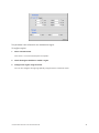
1
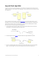
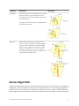
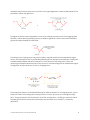
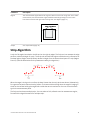
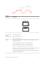
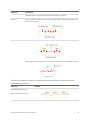
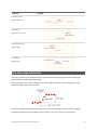
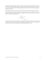
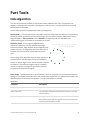
USER MANUAL
Gocator Measurement
Tool Technical Manual
Version 3.6.5.33 Revision: A
Copyright
Copyright © 2014 by LMI Technologies, Inc. All rights reserved.
Proprietary
This document, submitted in confidence, contains proprietary information which shall not be
reproduced or transferred to other documents or disclosed to others or used for manufacturing or any
other purpose without prior written permission of LMI Technologies Inc.
No part of this publication may be copied, photocopied, reproduced, transmitted, transcribed, or
reduced to any electronic medium or machine readable form without prior written consent of LMI
Technologies, Inc.
Trademarks and Restrictions
Gocator™ is a registered trademark of LMI Technologies, Inc. Any other company or product names
mentioned herein may be trademarks of their respective owners.
Information contained within this manual is subject to change.
This product is designated for use solely as a component and as such it does not comply with the
standards relating to laser products specified in U.S. FDA CFR Title 21 Part 1040.
Contact Information
For more information, please contact LMI Technologies.
LMI Technologies, Inc. 1673 Cliveden Ave.
Delta, BC V3M 6V5
Canada
Telephone: +1 604 636 1011
Facsimile: +1 604 516 8368
www.lmi3D.com
Gocator Measurement Tool Technical Manual
2
Table of Contents
Copyright
2
Table of Contents
3
Introduction
4
Profile Tools
5
Feature Points
5
Fit Lines
7
Gap and Flush Algorithm
8
Groove Algorithm
12
Strip Algorithm
16
Strip Start and Terminate Conditions
19
Strip Step Edge Definitions
21
Part Tools
23
Hole Algorithm
23
Opening Algorithm
25
Stud Algorithm
28
Common Parameters
30
Decisions
30
Output Filters
31
Regions
31
Gocator Measurement Tool Technical Manual
3
Introduction
Several of LMI's measurement tools use complex algorithms to find features and then return
measurements. This documentation describes the algorithms used by the following tools profile tools:
l
Gap and Flush
l
Groove
l
Strip
And the following whole part tools:
l
Hole
l
Stud
l
Opening
Gocator Measurement Tool Technical Manual
4
Profile Tools
Feature Points
Many profile measurements involve estimating the locations of feature points and then making
comparisons between the feature points. The following types of points can be identified.
Point Type
Examples
Top
Finds the point with the maximum Z value in the region of
interest.
Bottom
Finds the point with the minimum Z value in the region of
interest.
Left
Finds the point with the minimum X value in the region of
interest.
Right
Finds the point with the maximum X value in the region of
interest.
Average
Determines the average location of points in the region of
interest.
Gocator Measurement Tool Technical Manual
5
Point Type
Examples
Corner
Finds a dominant corner in the region of interest, where
corner is defined as a change in profile slope.
Top Corner
Finds the top-most corner in the region of interest, where
corner is defined as a change in profile shape.
Bottom Corner
Finds the bottom-most corner in the region of interest,
where corner is defined as a change in profile shape.
Left Corner
Finds the left-most corner in the region of interest, where
corner is defined as a change in profile shape.
Right Corner
Finds the right-most corner in the region of interest,
where corner is defined as a change in profile shape.
Rising Edge
Finds a rising edge in the region of interest.
Gocator Measurement Tool Technical Manual
6
Point Type
Examples
Falling Edge
Finds a falling edge in the region of interest.
Any Edge
Finds a rising or falling edge in the region of interest.
Median
Determines the median location of points in the region of
interest.
Fit Lines
Some measurements involve estimating lines in order to measure angles or intersection points. A fit line
can be calculated using data from either one or two fit areas.
A line can be defined using one or two areas. Two areas can be used to bypass discontinuity in a line
segment.
Gocator Measurement Tool Technical Manual
7
Gap and Flush Algorithm
The gap and flush tools use the same algorithm to find a feature. This algorithm first searches for two
regions on each side: a surface region and an edge region. (See the tables below for the parameters used
by the algorithm.)
After the algorithm finds the regions, it places a feature point in the surface region based on a set of
parameters. You can control the measurement regions for the left and the right side. A measurement
region defines the region in which the measurement tool will search for the feature points. Feature
points are located on each side using the following algorithm.
1. On the left side, search from left to right to find a surface area with data that covers at least the
Surface Width. On the right side, search from right to left.
2. If a surface region is found, fit a line, called the surface line, using the data within the area.
3. Search for a valid edge region that is located at least Surface Offset away from end of the surface
region. If a surface region is not found, move along the search direction and repeat step 1.
Gocator Measurement Tool Technical Manual
8
A valid edge region is detected when an edge matches the Nominal Radius or when the depth
exceeds the Minimum Depth. The search algorithm uses the Void Width Max to distinguish between
an actual edge from an area of missing data (referred to as void).
4. If a valid edge region is detected, a model fit is applied to the surface and edge regions to accurately
determine the region positions and feature point locations. The model fit takes into account the
Surface Width, Surface Offset, Edge Angle and the Edge Type parameters.
Parameters
Parameter
Description
Gap Width Max
The maximum width of the gap. Allows the tool to filter gaps longer than the expected width. This could
be used to single out the correct gap when there
are multiple gaps in the field of view.
Gocator Measurement Tool Technical Manual
Illustration
9
Parameter
Description
Reference Side
Defines the side on which the gap is calculated.
Measurement
Axis
Defines the direction that the gap is calculated.
Gap tool only
Illustration
Surface: In the direction of the fitted surface line of
the reference surface.
Edge: In the direction perpendicular to the edge of
the reference surface.
Distance: The Cartesian distance between the two
feature locations.
Decision
See Decisions (page 30).
Region
See Regions (page 31).
Output
See Output Filters (page 31).
Left/Right Side Parameters
Parameter
Description
Void Width
The maximum width of the missing data caused by
occlusion or data dropout. A larger value prevents
the algorithm from registering a section of missing
data as an edge.
Max
Illustration
Setting the value to 0 causes the algorithm to try to
detect an edge in every missing data section.
Gocator Measurement Tool Technical Manual
10
Parameter
Description
Minimum
Depth
Defines the minimum depth before an opening
could be considered to have a potential edge. The
depth is the perpendicular distance from the fitted
surface line.
Surface Width
The width of the surface area in which laser data is
used to form the fitted surface line. This value
should be as large as the surface allows.
Surface Offset
The distance between the edge region and the
surface region. Setting a small value allows the
edge within a tighter region to be detected.
However, the measurement repeatability could be
affected if the data from the edge are considered
as part of the surface region (or vice versa). A rule
of thumb is to set the Surface Offset equal to the
Illustration
Nominal Radius.
Nominal Radius
The radius of the curve edge that the algorithm
uses to locate the edge region. The algorithm
searches for a start position in which the remaining
data most resemble a circle of the specified nominal radius.
Gocator Measurement Tool Technical Manual
11
Parameter
Description
Edge Angle
A point on the best fit circle to be used to calculate
the feature point. The selected point is on the
circumference at the specified angle from the start
of the edge region.
Illustration
The angle is measured from the axis perpendicular
to the fitted surface line.
Edge Type
Defines the type of feature point and it can be
either a corner or a tangent. A tangent edge point
is the point selected based on the defined Edge
Angle. A corner edge point is the intersect point
between the fitted surface line and a edge line
formed by interpolating the points at and after the
tangent within the edge region.
Groove Algorithm
The groove measurement tool first locates valley along the profile line. The bottom point of a valley, the
valley point, is the first estimation of the position of the groove bottom. For each valley, the algorithm
searches for corner to the left and to the right to find the groove corners. A groove candidate is found
when the groove corners are located on the left and right before the next valley is reached. Two groove
Gocator Measurement Tool Technical Manual
12
candidates may share the same corner as shown in the right image below. (See the tables below for the
parameters used by the algorithm.)
The algorithm derives search parameters from the user settings to prevent noise from triggering false
detections. When detecting multiple grooves, an adaptive algorithm is used to ensure that candidate
grooves are approximately the same scale.
The valley points of open grooves may not be visible or may fall outside of the measurement region.
Voids in the data (regions with no profile data) between pairs of valid points are detected. A valley point
is added midway between the pair of valid points. The Z position of the valley point is either the
minimum groove depth below the lower of the corners or the bottom edge of the measurement region.
The algorithm then proceeds as if to find a U-shaped groove.
The actual groove bottom is calculated differently for different shapes. For a V-shaped groove, a line is
fitted to the sides of the valley points starting from the corners, up to (but not including) the valley
point. The groove bottom is the intersection of the left and right lines. Line fitting is used such that an
accurate groove bottom can be found even when the real bottom is not visible (i.e., blocked by
reflections).
Gocator Measurement Tool Technical Manual
13
For U-shaped and open groove, the distance from each point within the groove (including the added
point for open-shaped groove) is projected onto the width line. The groove bottom's X is at the centroid
of the projected values along the width. The groove bottom's Z is at the maximum depth of the groove.
Groove candidates that do not meet the minimum and maximum width and depth settings are rejected.
The width and depth measurements are invariant to the groove rotation. The width is the distance
between the groove corners and the depth is perpendicular distance of the groove bottom from the
groove width.
Parameters
Parameter
Description
Shape
Shape of the groove
Gocator Measurement Tool Technical Manual
14
Parameter
Description
Location
Specifies the location type to return
(Groove X and
Groove Z
measurements
only)
Bottom - Groove bottom. For a U-shape and open-shape groove, the X position is at the the
centroid of the groove. For a V-shape groove, the X position is at the intersection of lines
fitted to the left and right sides of the groove. See algorithm section below for more
details.
Left - Groove's left corner.
Right - Groove's right corner.
Select Type
Specifies how a groove is selected when there are multiple grooves within the
measurement area.
Maximum Depth - Groove with maximum depth.
Index from The Left - 0-based groove index, counting from left to right
Index from the Right - 0-based groove index, counting from right to left.
Index
0-based groove index.
Minimum Depth
Minimum depth for a groove to be considered valid.
Minimum Width
Minimum width for a groove to be considered valid. The width is the distance between the
groove corners.
Maximum Width
Maximum width of a groove to be considered valid. If set to 0, the maximum is set to the
width of the measurement area.
Decision
See Decisions (page 30).
Gocator Measurement Tool Technical Manual
15
Parameter
Description
Region
The measurement region defines the region in which to search for the groove. For a stable
measurement, the measurement region should be made large enough to cover some
laser data on the left and right sides of the groove. See Regions (page 31).
Output
See Output Filters (page 31).
Strip Algorithm
A strip is a flat region bounded on the left and on the right by edges. The Strip tool can measure the edge
positions, width and height of a strip. The Strip tool assumes that regions outside the strip, referred to as
the base regions (Region A and D below), deviate in height from the start and end parts of a strip (Region
B and C). (See the tables below for the parameters used by the algorithm.)
When the target is sitting on the surface, the base is lower than the strip (as shown above). Alternatively
for a groove the base is above the strip surface. The base could be missing when the target is hanging in
the air or the surface holding the target falls outside the sensor's active area. You can control the base
type in the measurement panel.
The Strip tool can detect multiple strips. You can select an ROI, referred to as the measurement region,
from which the algorithm search for multiple strips.
Gocator Measurement Tool Technical Manual
16
Parameters
Parameter
Description
Base Type
Specifies if the strip has a base or not.
Location
Specifies the strip position from which the measurements are performed.
(Strip Height, Strip X,
and Strip Z
measurements only)
Left - Left edge of the strip.
Right - Right edge of the strip.
Center - Center of the strip.
Left Edge
Specifies the features that will be considered as the strip's left edge. You can select
more than one condition.
Rising - Rising edge detected based on the strip edge parameters.
Falling - Falling edge detected based on the strip edge parameters.
Data end - First valid profile data point in the measurement region.
Void - Gap in the data that is larger than the maximum void threshold. Gaps connected
to the measurement region's boundary are not considered as a void.
See "Strip Start and Terminate Conditions" in the Algorithm Technical User Manual for
the definitions of these conditions.
Gocator Measurement Tool Technical Manual
17
Parameter
Description
Right Edge
Specifies the features that will be considered as the strip's right edge. You can select
more than one condition.
Rising - Rising edge detected based on the strip edge parameters.
Falling - Falling edge detected based on the strip edge parameters.
Data end - Last valid profile data point in the measurement region.
Void - Gap in the data that is larger than the maximum Void parameter. Gaps
connected to the measurement region's boundary are not considered as a void.
See "Strip Start and Terminate Conditions" in the Algorithm Technical User Manual for
the definitions of these conditions.
Select Type
Specifies how a strip is selected when there are multiple strips within the
measurement area.
Best - The widest strip.
Index from The Left - 0-based strip index, counting from left to right
Index from the Right - 0-based strip index, counting from right to left
Index
0-based strip index.
Minimum Edge
Height
Specifies the minimum deviation from the strip base. See "Strip Step Edge Definitions"
in the Algorithm Technical User Manual on how this parameter is used for different
base types.
Edge Support Width
Specifies the width of the region around the edges from which the data is used to
calculate the step change. See "Strip Step Edge Definitions" in the Algorithm Technical
User Manual on how this parameter is used by different base types.
Edge Transition
Width
Specifies the nominal width needed to make the transition from the base to the strip.
See "Strip Step Edge Definitions" in the Algorithm Technical User Manual on how this
parameter is used by different base types.
Maximum Void
The maximum width of missing data allowed for the data to be considered as part of a
strip when 'Void" is selected in the Left or Right Edge parameter. This value must be
smaller than the Edge Support Width.
Gocator Measurement Tool Technical Manual
18
Parameter
Description
When occlusion and exposure causes data drops, users should use the gap filling
function to fill the gaps.
Minimum Strip Width
Specifies the minimum width for a strip to be considered valid.
Tilt
Enables/disables tile correction.
Decision
See Decisions (page 30).
Region
The measurement region defines the region in which to search for the strip. If
possible, the region should be made large enough to cover the base on the left and
right sides of the strip.
See Regions (page 31) for more information.
Output
See Output Filters (page 31).
Strip Start and Terminate Conditions
The Strip tool allows you to define how a strip starts and ends. The Left Edge parameter controls how a
strip starts and the Right Edge parameter controls how a strip ends.
Start / terminate conditions
Condition
Description
Rising
Rising step edge detected based on the strip edge parameters. See Strip Step Edge
Definitions (page 21) for details on how the step edge is detected.
Falling
Falling step edge detected based on the strip edge parameters. See Strip Step Edge
Gocator Measurement Tool Technical Manual
19
Condition
Description
Definitions (page 21) for details on how the step edge is measured.
Data end
The first (for the left edge) or the last (for the right edge) valid profile data point in the
measurement region.
Void
Gaps in the data that are larger than the maximum void threshold.
Gaps at the ends of the measurement region's boundary are not considered as a void.
The following examples show how the parameters affect the strip detection in different scenarios.
Left and Right Edge conditions
Condition
Example
Left: Rising, data end, void
Right: Falling, data end, void
Gocator Measurement Tool Technical Manual
20
Condition
Example
Left: Rising, void
Right: Falling, void
Left: Rising
Right: Data end, void
Left: Data end, void
Right: Falling
Left: Falling
Right: Rising
Strip Step Edge Definitions
The Strip tool detects step edges based on the parameters Base Type, Edge Transition Width, Edge
Support Width, and Minimum Edge Height.
When Base Type is set to Flat, the regions around the edges are visible and the edge positions are
between the base and the strip surface.
The Minimum Edge Height parameter defines the size of the step edge. The Edge Transition Width
parameter specifies the nominal width of the transition, from the base to the strip surface.
Gocator Measurement Tool Technical Manual
21
The Edge Support Width parameter defines the width of the region around the edges from which the
data is used to measure the step change. This region should be relatively smooth and flat. To improve
noise immunity, the height level of the Edge Support Width parameter is calculated by averaging the
data within the region.
When the base is set to None, the tool looks for continuous sections that are wider than the Edge
Support Width parameter and have no data points that deviate positively or negatively more than the
value of the Minimum Edge Height parameter. The height level of the continuous region is calculated
based on the fitted line as shown below.
The algorithm then backs off by the value of the Edge Transition Width parameter and uses the data up
to the back-off point to create the fitted line and projects the edge point on the line. This step prevents
the points near the end of a rounded strip from affecting the height of the strip.
Gocator Measurement Tool Technical Manual
22
Part Tools
Hole Algorithm
The Hole tool processes the data in three phases: Search, Measure, and Filter. The algorithm can
separate out background information that appears inside the hole. It can also detect holes that only
partially appear in the data.
See the tables below for the parameters used by the algorithm.
Search phase - The tool searches for coarse data transitions (edge data) and performs a coarse fitting
of the hole model (specified by the orientation angles and the nominal value) to determine the most
likely candidate. If Tilt Correction is set to Autoset, the algorithm uses the data within the
measurement region to estimate the orientation of the part.
Measure phase - A more rigorous edge detection
algorithm is applied to precisely determine the edges
around the feature. Edge detection at this stage will reject
outliers and noise. The algorithm requires at least 25% of
the data around the hole for the candidate to remain
valid.
The accuracy of the algorithm improves when the points
are spread more evenly along the hole's circumference.
The set of refined edges is then used to locate and inspect
the feature. If the Reference Regions option is enabled
and set to AutoSet, the edges are also used to calculate
the location of the reference regions.
Filter phase - The detected location and dimensions are then compared to the nominal and tolerance
settings. If the refined feature falls within the measurement region and its measurements fit within the
specified tolerance, the results are reported. If not, an invalid result is returned.
Parameters
Parameter
Description
Nominal Radius
Expected radius of the hole.
Radius Tolerance
The maximum variation from the nominal radius (+/- from the
nominal radius).
Reference Regions
The algorithm uses the Reference Regions option to calculate
the Z position of the hole. It is typically used in cases where the
surface around the hole is not flat.
Gocator Measurement Tool Technical Manual
23
Parameter
Description
When this option is set to Autoset, the algorithm automatically
determines the reference region. When the option is not set to
Autoset, the user manually specifies the reference region. The
location of the reference region is relative to the detected
center of the hole and positioned on the nominal surface plane.
When the Reference Regions option is disabled, the tool
measures the hole's Z position using all the data in the
measurement region, except for a bounding rectangular region
around the hole.
Tilt Correction
Tilt of the target with respect to the alignment plane.
When this option is set to Autoset, the tool automatically
detects the tilt. Otherwise, the user must enter the angles
manually. Autoset requires the measurement region to cover
more areas on the surface plane than other planes.
The results from the Plane X and Y tool can be used for angles X
and Y parameters.
Partial Detection
Gocator Measurement Tool Technical Manual
Enable if only part of the hole is within the measurement
region. If disabled, the hole must be completely in the region of
interest for results to be valid.
24
Parameter
Description
Decision
See Decisions (page 30).
Region
See Regions (page 31).
Output
See Output Filters (page 31).
Opening Algorithm
The Opening tool processes the data in three phases: Search, Measure, and Filter.
See the tables below for the parameters used by the algorithm.
Search phase - The tool searches for coarse data transitions (edge data) and performs a coarse fitting
of the opening shape (specified by the orientation angles and the nominal dimensions) to determine the
most likely candidate. If Tilt Correction is enabled, the algorithm uses the flat surface in the
measurement region to estimate the orientation of the part.
Measure phase - A more rigorous edge detection
algorithm is applied to precisely determine the
edges around the feature. Edge detection at this
stage will reject outliers and noise. The algorithm
requires opposite sides and ends to be associated
with a comparable number of edge pixels, with the
weaker side or end having at least 25% of the
stronger.
The set of refined edges is then used to locate and
inspect the feature. If the Reference Regions
setting is enabled, the edges are also used to
calculate the location of the reference regions.
Gocator Measurement Tool Technical Manual
25
Filter phase - The detected location and dimensions are compared to the nominal and tolerance
settings. If the refined feature falls within the measurement region and its measurements fit within the
specified tolerance, the results are reported. If not, an invalid result is returned.
Parameters
Parameter
Description
Type
Rounded Slot, Rectangle.
Nominal Width
Nominal width of the opening.
Nominal length
Nominal length of the opening.
Nominal Angle
Nominal angle of the opening. The default orientation is the length of the opening
along the X axis.
The diagram above illustrates the case where the surface is not tilted. When the
surface is tilted, the orientation is defined with respect to the normal of the surface,
not with respect to the X-Y plane
Nominal Radius
Nominal radius of the opening ends. If the opening type is set to rectangular, the
radius setting is disabled. The opening has an oval shape if the radius is equal to ½
of the width. The opening is a rounded rectangle when the radius is less than ½ of
the width.
Gocator Measurement Tool Technical Manual
26
Parameter
Description
Width Tolerance
The maximum variation from the nominal width (+/- from the nominal value).
Length Tolerance
The maximum variation from the nominal length (+/- from the nominal value).
Orientation Tolerance
The maximum variation from the nominal orientation (+/- from the nominal value).
Reference Regions
The algorithm uses reference regions to calculate the Z position of the hole.
Reference regions are relative to the center location of the feature. This option is
typically used in cases where the surface around the opening is not flat.
When the Reference Regions setting is disabled, the tool measures the hole's Z
position using the all data in the measurement region, except for a bounding
rectangular region around the opening.
Gocator Measurement Tool Technical Manual
27
Parameter
Description
With one or more reference region, the algorithm calculates the Z positions as the
average values of the data within the regions.
When the user places the reference region manually, all of the data is used, whether
the data is inside or outside the opening. The user should place the reference region
carefully.
Tilt Correction
Tilt of the target with respect to the alignment plane. Set to Auto-Set to have the tool
automatically detect the target's tilt, or enter the angles manually. Auto-Set requires
the measurement region to cover more areas on the surface plane than other
planes.
The results from the Plane X and Y tool can be used for angles X and Y parameters.
Decision
See Decisions (page 30).
Region
See Regions (page 31).
Output
See Output Filters (page 31).
Stud Algorithm
The Stud algorithm measures the stud in three steps: searching for the tip, finding the reference plane,
and shaft fitting.
See the tables below for the parameters used by the algorithm.
Searching for the tip - The algorithm looks for the approximate location of the tip. If Auto-Tilt is
enabled, the algorithm uses the flat surface around the tip to estimate the orientations of the part. The
approximate tip is the location of the highest (maximum Z) pixel after correction for the nominal tilt
angle.
Finding the reference plane - The reference regions are positioned using the approximate tip, the
nominal angle values, and the nominal stud length. Compared to the hole/opening, misplaced stud
reference regions are more likely to cause a failure to produce any measurement.
Gocator Measurement Tool Technical Manual
28
Shaft fitting - The shaft region is determined
based on the approximate tip position, the nominal
angles, the reference plane position, and the stud
nominal size parameters. Shaft fitting is successful
if the algorithm can fit at least three circles with the
stud diameter along the shaft. Fitting each circle
requires sufficient data along the top portion the
shaft. Because of occlusions, the bottom of the
shaft is often not visible to the sensor and the
algorithm is designed to handle this situation.
Parameters
Parameter
Description
Nominal Stud Radius
Expected radius of the stud.
Nominal Stud Length
Expected length of the stud.
Base Height
The height above the base surface that will be ignored when the (truncated) cone is
fit to the stud data.
Tip Height
The height from the top of the surface that will be ignored when the (truncated)
cone is fit to the stud data.
Radius Offset
The distance from the tip of the stud from which the radius is measured.
Reference Regions
The algorithm uses reference regions to calculate the base plane of the stud.
Reference regions are relative to the base of the stud.
Tilt Correction
Tilt of the target with respect to the alignment plane. Set to Auto-Set to have the tool
automatically detect the tilt, or enter the angles manually. Auto-Set requires the
measurement region to cover more areas on the surface plane than other planes.
The results from the Plane X and Y tool can be used for angles X and Y parameters.
Decision
See Decisions (page 30).
Region
See Regions (page 31).
Output
See Output Filters (page 31).
Gocator Measurement Tool Technical Manual
29
Common Parameters
Decisions
Results from a measurement tool can be compared against minimum and maximum thresholds to
generate pass / fail decisions. The decision state is pass if a measurement value is between the minimum
and maximum threshold; in the user interface, these values are displayed in green. Otherwise, the
decision state is fail; in the user interface, these values are displayed in red.
Value (50.380) is within the decision thresholds (Min: 80, Max:100). Decision: Pass
Value (102.928) is outside the decision thresholds (Min: 80, Max: 100). Decision: Fail
Along with measurement values, decisions can be sent to external programs and devices. In particular,
decisions are often used with digital outputs to trigger an external event in response to a measurement.
Gocator Measurement Tool Technical Manual
30
Output Filters
Output filters can be applied to measurement values before they are output from the Gocator sensors.
Operation
Description
Scale and Offset
The Scale and Offset settings are applied to the measurement value according to
the following formula:
Scale * Value + Offset
Scale and Offset can be used to transform the output without the need to write a
script. For example, to convert the measurement value from millimeters to
thousands of an inch, set Scale to 39.37.
Hold Last Valid
Hold the last valid value when the measurement is invalid. Measurement is invalid if
there is no valid value.
Smoothing
Apply moving window averaging to reduce random noise in a measurement output.
The averaging window is configured in number of frames.
If Hold Last Valid is enabled, smoothing uses the output of the Hold Last Valid filter.
To configure the output filters:
1.
Select a measurement.
Click on the + in a measurement panel to expand it. Click the arrow next to Output to expand the panel.
2.
Enable filters and configure the settings.
Regions
The Region parameter is used to limit the region in which a measurement will occur. See the individual
tools for details on the best way to use this parameter with each tool.
The parameter can be configured graphically using the mouse in the data viewer when the
Measurement page is active.
Some measurements use more than one region.
Gocator Measurement Tool Technical Manual
31
This parameter is also referred to as a measurement region.
To configure regions:
1.
Select a measurement.
Click on the + in a measurement panel to expand it.
2.
Check the Region checkbox to enable a region.
3.
Configure the region using the fields.
You can also configure the region graphically using the mouse in the data viewer.
Gocator Measurement Tool Technical Manual
32