1
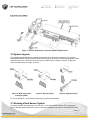
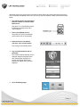
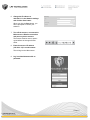
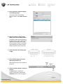
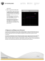
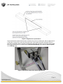
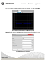
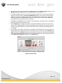
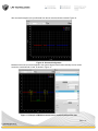
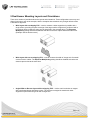
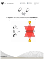
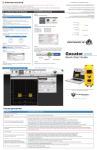
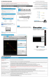
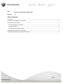
Title: Gocator 4.x Dual-Sensor Setup Guide Revision: 1.1 Table of Contents 1 Overview ................................................................................................................................................................. 2 2 Software and Hardware Requirements ................................................................................................................... 2 3 Dual-Sensor Setup Steps........................................................................................................................................ 2 3.1 Connecting the Components ............................................................................................................................ 2 3.2 System Layouts ................................................................................................................................................ 3 3.3 Running a Dual-Sensor System ....................................................................................................................... 3 4 Alignment and Measurement Example ................................................................................................................... 7 5 Dual-Sensor Mounting Layouts and Orientations ................................................................................................. 12 Page | 1 1 Overview This application note describes how to set up and use the Gocator’s built-in support for dual-sensor operation. The document is divided into two main parts. The first part is based on the user manual for all the basic setup steps, whereas the second part describes in detail how to align the system into a common coordinate frame and briefly explains how measurement tools can be used on the combined data. The aim of this document is to provide you with all the required setup steps to get a dual-sensor system operating. The guide requires two Gocator sensors of the same model, running the same firmware version. 2 Software and Hardware Requirements Requirements Details Gocator Firmware Gocator 4.0.9.136 or later Gocator Series Gocator 2300 family 3 Dual-Sensor Setup Steps In a dual-sensor system, two Gocator sensors work together to measure an object, typically in order to cover a wider field of view (FOV) or to measure thickness. The sensor system can deliver combined 3D data in a common coordinate frame, provided by the Gocator’s built-in alignment support. The controlling sensor is referred to as the Main sensor, and the helper is referred to as the Buddy sensor. Gocator’s software recognizes three dual-sensor installation layouts, which are summarized in the following table: Layout Description and usage scenario Wide Sensors are mounted side by side to scan a wide target. Reverse Sensors are mounted side by side as in the Wide layout, but the Buddy sensor is rotated 180 degrees around the z-axis to prevent occlusion along the y-axis. Opposite Sensors are mounted facing each other, typically to measure the thickness of material. These layouts are illustrated in System Layouts. 3.1 Connecting the Components Master 400 must be used to connect two sensors in a dual sensor system. Gocator 23x0 Master cordsets are used to connect the sensors to the Master. Page | 2 Figure 1: Gocator 2300 Family Connection (Master 2400 pictured) 3.2 System Layouts The examples below illustrate the possible mounting layouts for dual-sensor systems. The mounting relationships between the Main and the Buddy sensor must be as shown in the following diagrams. When viewed from the rear, in Wide and Reverse layout, the Main sensor is always on the left. In Opposite layout, the Main sensor is always on the top. Figure 2: Wide layout (with overlapping FOV) Figure 3: Reverse layout Figure 4: Opposite layout For more information, see Dual-Sensor Mounting Layouts and Orientations. 3.3 Running a Dual-Sensor System All Gocator sensors are configured to use 192.168.1.10 as the default IP address. For a dual-sensor system, the Main and Buddy sensors must run the same firmware version and must be assigned unique Page | 3 addresses before they can be used on the same network. Before proceeding with these instructions, connect the Main and Buddy sensors one at a time (to avoid an address conflict) and follow the steps below. 1. Turn off the sensors and unplug the Ethernet network connection of the Main sensor. Skip steps 1 to 3 if the Buddy sensor's IP address is already setup with a unique address. 2. Power up the Buddy sensor. The power LED (blue) of the Buddy sensor should turn on immediately. 3. Enter the sensor’s IP address (192.168.1.10) in a web browser. This will log into the Buddy sensor. 4. Log in as Administrator with no password. The interface display language can be changed using the language option. After selecting the language, the browser will refresh and the web interface will display in the selected language. 5. Go to the Manage page. Page | 4 6. Change the IP address to 192.168.1.11 in the Network settings and click the Save button. When you click the Save button, you will be prompted to confirm your selection. 7. Turn off the sensors, re-connect the Main sensor’s Ethernet connection and power-cycle the sensors. The sensors must be reset or powercycled before the change will take effect. 8. Enter the sensor’s IP address (192.168.1.10) in a web browser. This will log into the Main sensor. 9. Log in as Administrator with no password. Page | 5 10. Go to the Sensor System category on the Manage page. The serial number of the Buddy sensor is listed in the Visible Sensors area. 11. Select a sensor to assign as the Buddy and click the Assign button. The Buddy sensor will be assigned to the Main sensor, and its status will be updated in the System panel. Note that the firmware version on the Main and the Buddy must be the same for Buddy assignment to be successful. 12. Ensure that the Laser Safety input is high. 13. Go to the Scan page and ensure that Replay mode is off. When Replay mode is off, the slider is to the left. 14. Click on the Start button to start the sensors. The Start button is used to run sensors continuously, whereas the Snapshot button is used to trigger a Page | 6 single profile. 15. Move a target into the laser plane. If a target object is within the sensor’s measurement range, the data viewer will display the profile of the target and the sensor’s Range indicator LED will illuminate. In the data viewer’s drop-down box, select Left & Right to view data from both sensors at the same time. Note that sensors are referred to as Top, Bottom, Left, or Right in the Scan, Measure, and Output pages, The exact names used depend on the layout chosen. 4 Alignment and Measurement Example In order to use the dual-sensor setup to actually measure targets in a single combined field of view, the sensors have to be made aware of each other’s mounting location. In Gocator 4.0, this is done through the built-in Alignment function, which supports the alignment of the dual-sensor system into world coordinates. The example presented here is for the Wide layout scenario, that is, when the sensors are mounted side by side to cover a wider field of view. For wide multi-sensor systems, alignment bars are required to perform the system alignment according to the specification in Figure 5. The bar should not be made of a reflective or shiny material, but a brushed or matte metallic surface may still work. As a rule-of-thumb, the diameter of the reference holes should be at least 10 times the sensor’s X resolution. Page | 7 Figure 5: Alignment bar specifications Figure 6 shows two Gocator 2330 sensors mounted side by side in a Wide layout, with an alignment bar in their field of view (FOV). In this case the sensors are close together and their individual FOV’s are physically overlapping, which is suitable in applications where high resolution is required to scan a target that is larger than the FOV of a single sensor. Exposure Multiplexing was enabled in Sensor System on the Manage page. Figure 6: Dual-sensor setup with custom alignment bar Page | 8 Figure 7 shows what the unaligned profile data looks like in the data viewer. Note again that Left & Right must be selected in the data viewer’s drop-down selection box. Figure 7: Unaligned profiles from both the Main and the Buddy Alignment of the Gocator is done in the Alignment panel on the Scan page. Figure 8 shows the Alignment panel with the correct settings entered corresponding to the setup pictured above in Figure 6. Figure 8: Alignment panel with settings Note the following: Page | 9 The correct layout must be selected in the Layout section in the Sensor System category on the Manage page before alignment for a successful operation. See Figure 9. If the Main and Buddy sensors are mounted so that the camera from one sensor can detect the laser from the other sensor, the Exposure Multiplexing feature can be used to eliminate laser interference. Exposure multiplexing creates a time offset for laser exposures and ensures that interfering lasers are not strobed at the same time. Note that the use of exposure multiplexing may reduce the maximum frame rate. See Figure 9. Select Bar in the Target drop-down and enter the dimensions of the alignment bar. The distance between the holes is from center to center. Select Stationary in the Type drop-down for an alignment where the bar does not movie in the sensor’s FOV during alignment. This type of alignment does not calibrate the encoder resolution and is the recommended method if the encoder resolution has already been established or has not changed. If an encoder is connected to the system, it is possible to also calibrate the encoder resolution in a single operation by scanning the bar in the direction of travel. In this case, select Moving in the Type drop-down. The Width setting represents the width of the bar and is used by the alignment routine to establish the encoder resolution. The encoder resolution can also be manually entered in the Motion and Alignment category on the Manage page. Figure 9: Layout under Sensor System on Manage page (Wide layout selected) Page | 10 After successful alignment, the profile data from the two sensors should resemble Figure 10. Figure 10: Successful alignment Measurement tools can now be applied to the system-aligned data for dimensionally correct results across the combined field of view, as shown in Figure 11. Figure 11: Example of Width measurement on combined dual-sensor data Page | 11 5 Dual-Sensor Mounting Layouts and Orientations There are a number of possible dual-sensor layouts and orientations. These configurations are set up and aligned in the same way as the example, with the exception that sometimes only a single reference hole is needed for alignment. Wide layout with overlapping FOV – used to measure a wider target than is possible with a single sensor, providing complete coverage of the target surface. Alignment is performed with a bar with two holes, exactly the same way as described in the example above. The Exposure Multiplexing setting should be disabled so that the two sensors capture data at the same time. (Example used in this document.) Wide layout with non-overlapping FOV – used to measure the width of a large web of material such as metal or rubber. The Exposure Multiplexing setting should be disabled so that the two sensors capture data at the same time. Angled Wide or Reverse layout with overlapping FOV – used to avoid occlusions on targets with complicated shape and sharp corners. The sensors are angled in toward each other. Alignment is performed using a bar with a single hole. Page | 12 Opposite layout – used to measure true thickness of a target. The Exposure Multiplexing setting should be disabled so that the two sensors capture data at the same time. The two sensor’s lasers should be aligned to form a single plane. Alignment is performed using a bar with a single hole, as illustrated below. Page | 13