1
Installing the Panel
Gently tighten the lower screws to secure the panel to
the wall.
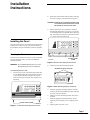
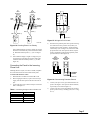
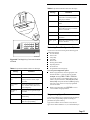
10) Insert the Quick Reference Card into the space at the
top, back side of the panel (see Figure 4). Make sure
that the “TEST WEEKLY” tab on the card is facing
out. Also, remember to fill this card out when the
install is complete.
9)
QUICK REFERENCE CARD
POWER
1
2
3
4
5
POLICE
6
7
8
9
0
FIRE
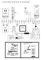
Refer to the wiring diagram on the back cover of this manual for basic wiring. Wire the following devices to the system, as necessary:
Hardwire sensors
Hardwire sirens and/or piezos
AC Power Transformer
For detailed information on installing peripheral and hardwire devices, see the Commander 2000 Reference Manual
and the installation sheets that accompany each device.
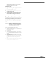
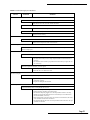
Refer to Table A.2 to calculate the hardwire device limit for
the system.
READY
STAY
Connecting Devices to the Panel
AWAY
NO DELAY STATUS BYPASS
TROUBLE
COMMAND
AUX
Connecting Hardwire Sensors to the
Panel
8333G29A.DS4
Figure 4. Quick Reference Card Location
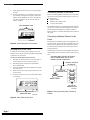
Running Wire to the Panel
You must run wire from the panel to phone, power, and
hardwire devices. Do not run wires near fluorescent lighting
or parallel to AC power lines.
To run wires to the panel’s wire access area:
1)
2)
3)
4)
5)
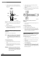
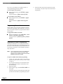
Drill holes for the necessary wire runs in the wall, at
the back of the wire access area (see Figure 5).
Run the appropriate wire between each hardwire
device and the panel.
Feed wires through the holes just drilled in the panel’s
wire access area.
Mark each wire run so that you know which wires are
for each device.
Tie-wrap or secure the wires to a solid structure whenever possible.
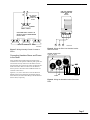
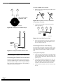
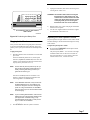
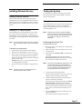
The panel has one hardwire input for wiring hardwire sensors to the panel. You can use either a normally open or normally closed configuration. Both configurations require a
4.7k ohm end-of-line (EOL) resistor as the last device for
circuit supervision.
Normally open contacts are wired in parallel (see Figure 6),
while normally closed contacts are wired in series (see Figure 7).
USE EITHER SINGLE CONTACT OR MULTIPLE
CONTACT SERIES WIRING BUT NOT BOTH
(SHOWN IN CLOSED ALARM STATE)
MULTIPLE CONTACTS
IN PARALLEL
4.7k Ohm EOL
RESISTOR 49-365
MAGNET
SINGLE CONTACT
POWER
1
2
3
4
5
POLICE
6
7
8
9
0
FIRE
READY
STAY
AWAY
NO DELAY
STATUS BYPASS
COMMAND
AUX
TROUBLE
4.7k Ohm EOL
RESISTOR 49-365
8333G20A.DS4
Figure 6. Wiring Normally Open Contacts in
Parallel
WIRE ACCESS AREA
8333G17A.DS4
Figure 5. Panel Wire Access Area
Page 2