1
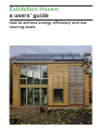
Exhibition House:
a users’ guide
how to achieve energy efficiency and low
running costs
1
1.00 Contents
1.00
Contents
2.00
Key data / 1
3.00
3.01
3.02
Introduction / 2
Purpose of users’ guide / 2
Project vision / 2
4.00
Overview of the house
and sustainability features / 3
Materials / 4
Services / 4
Rennovation and demolition / 5
4.01
4.02
4.03
10.00
10.01
10.02
10.03
10.04
10.05
Local amenity information / 22
Refuse / 22
Public transport / 22
Cycle routes / 22
Car parking / 22
Location of essential services / 22
11.00
Emergency information and
procedures / 23
Location of emergency
information / 23
Location of utility isolation / 23
Contact information / 23
11.01
11.02
11.03
5.00
5.01
5.02
5.03
5.04
5.05
5.06
5.07
5.08
5.09
5.10
5.11
5.12
5.13
5.14
5.15
Building fabric overview / 6
Masonry plinth wall / 6
Timber structure / 6
Timber cladding / 6
Chestnut shakes / 6
Trombé wall / 7
Air tightness membrane / 7
Floor screeds / 7
Cork and carpet floor finishes / 7
Sweet chestnut shingle roof / 8
Solar panel roof / 8
External wall / 8
Trombé wall / 9
Wall/window junction / 9
Ground floor construction / 10
Upper floor / external wall
junction / 10
6.00
6.01
6.02
6.03
6.04
Joinery overview / 11
Single leaf external doors / 11
Sliding folding doors / 11
Windows / 11
Sliding sun shade / 11
Address:
Exhibition House
Exhibition Mews
Bordon
Hampshire
GU35 0GY
7.00
7.01
7.02
7.03
7.04
7.05
Building services overview / 12
Keeping the house warm / 12
Keeping the house cool / 13
How to keep water bills down / 14
How to keep electric bills down / 14
The building services in detail / 14
Responsibility of:
Lee Burn, East Hampshire
District Council
Position:
Facilities manager
8.00
Users’ guide issue number:
1st edition
Date:
January 2013
8.03
8.04
Refit, rearrangement and
demolition considerations / 19
Altering the fabric of the building / 19
Altering the structure of the
building / 19
Lifetime Homes adaptations / 19
Design for demolition / 20
The garden / 21
Overview / 21
Terrace and lawn / 21
Garden shed / 21
Clothes dryer / 21
Water butts / 21
Composting bins / 21
Cold frame / 21
Raised beds / 21
Surface water drainage / 21
This users’ guide should be
kept at all times in:
Exhibition house, study
9.00
9.01
9.02
9.03
9.04
9.05
9.06
9.07
9.08
9.09
Electronic version available
from:
www.whitehillbordon.com
Prepared by:
Ian McKay of BBM Sustainable Design Limited
Guide design consultant:
Peter Brawne | Matter
8.01
8.02
2.00 Key data
2
3.00 Introduction
3.01 Purpose of user
guide
3.02 Project vision
This Users’ Guide sits alongside the
Operations and Maintenance Manual
(O&M Manual) prepared by Westridge
Construction who built the house. The
users’ guide provides an overview
of the ideas behind the design of the
house, its energy and resource efficient
strategies, as well as descriptions of
how elements are made and how they
work.
In order to demonstrate to existing and
future residents of Whitehill and Bordon
that green living can be enjoyable, the
Eco-town team commissioned Riches
Hawley Mikhail to design a two bedroom, four person exhibition house to
demonstrate the opportunities of living
a zero-carbon and sustainable lifestyle
as well as a showcase for some of the
technologies that such a lifestyle would
include. BBM Sustainable Design were
appointed to prepare the specification
and construction information whilst retaining the initial concept of the house.
In the interests of making it user
friendly, the guide has been conceived
to communicate predominantly through
illustrations and photographs with
supporting written descriptions and annotations.
The householder should also be aware
that if carrying out maintenance and
material alterations to the building
fabric and/or electrical and mechanical services of the property there is a
digital appendix to the User Guide with
a schedule of user guide updates. Use
this document to record the nature, date
and responsibility for the work.
The master electronic version of this
Microsoft Office document is held at
East Hampshire District Council, Penns
Place, Petersfield, Hampshire, GU31
4EX
Our brief required the house to be
designed as an exhibit, open to the
public for a year, and then in the future
it would become a family home. The
project has provided a rare opportunity to test new design solutions and
technologies for carbon neutral living
without losing sight of the role that design plays in creating a liveable home:
we wanted visible demonstrations of
energy use and technologies, but not
at the expense of a comfortable and
pleasant living environment.
Learning from the design and construction process for the exhibition house
doesn’t end when the building work
is over. This is why we have commissioned a User’s Manual. The different
technologies – photovoltaic panels, solar thermal panels, inter-seasonal heat
store, rainwater harvesting, mechanical ventilation and heat recovery unit,
require some understanding in order to
achieve the best performance from the
home. We want future occupants and
visitors to understand how the house
works and that management and maintenance is as important as design and
construction.
The exhibition house is one of six exhibition buildings on the former Ministry
of Defence fire station site. The main
exhibition building is the refurbishment
of the existing Edwardian former fire
station, designed by BBM Sustainable
Design. The building is now the ‘Ecostation’ with exhibition space, a lecture
theatre and office space. There will also
be exhibitions of history and local ecology and an adjacent old stable block
has been retained. The refurbishment
has focused on improving the thermal
performance of the building – adding insulation to some of the floors, walls and
roof as well as installing new energy
efficient gas boilers.
In 2013, the construction of three terraced houses will commence. These
will demonstrate how eco-homes can
be affordable, and provide a model for
future homes in the town. Radian Housing Group is the client for this project
working with Ash Sakula Architects.
The final project will be the refurbishment of the existing drill tower. It will be
clad in solar panels and contribute to
the energy efficiency of the Eco-station.
Together these projects should provide
a learning resource for the Eco-town
and beyond.
3
4.00 Overview of the house and sustainability features
�
�
��
���
��
��
�
�
�
���
�
��
���
���
��
��
��
��
��
Ground floor
��
north
�
�
�
�
���
���
Exhibition house floor plans at a scale of
1:200
���
Key:
�
�
���
�
��
���
���
���
�
First floor
�
�
�
�
�
�
���
���
���
�
�
���
Loft
�
The rooms in the house are organised
to respond to both the environmental
and exhibition requirements of the
brief. A central circulation route allows
easy movement of the public as for
an exhibition. In terms of reducing the
demand for energy to heat the house,
the sedentary spaces: the living room,
dining area, main bedroom and study,
are located in the warmest part of the
house. These south facing rooms benefit from two passive design features
built into the south facing wall – a winter
garden and a trombé wall. The kitchen,
bathrooms and the entrance hall are in
the coldest part of the house, forming
a buffer to the walls that face north and
therefore don’t benefit from the warmth
of the sun.
1. Driveway
2. Entrance lobby
3. Hall
4. Accessible W.C.
5. Living room
6. Trombé wall
7. Winter garden
8. Kitchen / diner
9. Shed storage
10. Bin store
11. Water collection
12. Garden
13. Inter-seasonal heat store
(underground)
14. Main bathroom
15. Bedroom 1
16. Void
17. Mezzanine level
18. Bedroom 2
19. Services cupboard
20. Outline of possible future
Lifetime Homes lift access
21. Attic
22. Photovoltaic and solar
thermal panels on standing seam metal
roof
23. Sweet chestnut shingle roof
�
The winter garden traps heat between
two layers of glass in winter, while in
summer the outer layer of glazing can
be left permanently open, providing a
covered area at ground floor for a table
and chairs, and a balcony off the master bedroom at first floor level.
The trombé wall works from the sun
heating an area of clay blocks that
provide thermal mass, which stores and
radiates heat internally, a timber screen
gives shade so the wall does not overheat in the summer.
The open circulation not only creates
views to different floors but it also acts
as a route for passive ventilation to all
the rooms. At the centre of the stair-
case is a service duct connecting to the
mechanical ventilation unit.
The ground floor is fully wheelchair
accessible, conforming to the requirements of Lifetime Homes. This standard
comprises 16 design criteria that can
be universally applied to new homes
to make them more convenient and
accessible to the broadest range of
homeowners including elderly people
and those with physical disabilities. It includes future adaptation features which
are explained in section 8.0.
The design has considered future
changes to the house and allows for
demolition and salvage.
4
4.00 Overview of the house and sustainability features
���
���
���
���
���
���
���
���
���
Understanding
������������the
���basic
�����principles
�
behind the low energy design of the
������������
house
will help the homeowner interact
������������������
and
control the various technologies as
��������
well
as exploit the most energy efficient
�������������������
modes
of operation.
���������������
���������������
�����������������
�������������������
����������������
�������������
Buildings
impact the environment when
��������������������
they
are built, when they are in use and
����������
�����������������������������
finally
when they are demolished. With
��������������
good
design we can minimize these
�����������������
impacts
at every stage of the energy
�������������
lifecycle
�������� of the house. Starting with the
energy
and environmental impact of
�������������������
how
the house was built, the design�������������
���������������������
ers
have opted mainly for materials
������������������������������
that
have been grown, such as timber
���������������������������
products.
There is generally far less
���������
energy
involved
in making buildings out
��������������������������
of wood
than say, brick and concrete.
���������������������������
The����������������
material itself is renewable (it can
�������������������������������
be
re-grown) and wood products lock
4.01 Materials
��
��
��
Section
A-A
���������
��
Sectiion
A-A
��
��
��
Section
C-C
������
�����
Sectiion
C-C
���
���
���
���
���
���
���
��
���
��
��
Section
Sectiion
B-B
�������B-B
��
��
��
Section
D-D
Sectiion
D-D
������
�����
��
carbon out of the atmosphere through
photosynthesis, as a result of which
wood has no carbon emissions.
25 years growth cycle
100 + years growth cycle
4.02 Services
The house has been designed to
nurture low carbon lifestyles for its
inhabitants. It incorporates simple technologies such as the external clothes
line, a bike store to support low carbon
transport, recycling storage in the
kitchen and garden shed and a garden
design which supports the growing of
food and recycling of food waste. The
home working study points to a more
flexible and efficient way of working
where daily commuting can be avoided.
near left above: Exhibtion house is predominantly built out of prefabricated timber. Building in timber is good for the environment as
there is minimal processing energy required
and in itself it is a form of ‘carbon locking’.
near left bottom: Exhibtion house is externally clad in glue-laminated lengths of
coppiced sweet chestnut which is grown and
manufactured in the Sussex Weald.
far left: The coppiced technique of harvesting timber benefits from a mature root stock
to regenerate the timber at a far greater rate
than that of conventional logging (far left).
As such it is regarded as the fastest way of
growing hardwood and ‘locking carbon’!
5
4.00 Overview of the house and sustainability features
There is also an electric car charging
point fitted within the bike shed. While
it utilizes daytime energy produced by
the solar photovoltaic panels on the
roof of the house, it will provide truly low
carbon transport.
It also has a range of energy systems
which can help the homeowner cut
down on utility bills. (See section 7.0)
The most important aspect of designing
a low energy house is first to ensure
you have reduced the demand for heat
and power. In the Exhibition house
this means really thick walls, roofs and
floors filled with thermal insulation. So
much insulation in fact, that the house
effectively will not need any form of
artificial space heating input for all but
the very dullest and coldest days of the
year. You can read more detail on the
materials and construction of the exhibition house in sections 5.0 and 6.0.
The house also makes its own energy
both passively and actively. It uses the
sun’s energy to produce heat and electrical energy and it collects rainwater
for use in the flushing of the downstairs
WC and washing machine. It has water
efficient sanitary fittings, LED lighting
technology and a power ‘OFF’ button
by the front door, which you can press
when you want to turn off all the left on
lights and non-essential power sockets
in the house. You can read more on
building services in section 7.0.
4.03 Renovation and
Demolition
Buildings are a valuable resource for
society as a whole and they must be
capable of adaptation for new uses. If
and when their useful life comes to an
end, then the constituent parts of the
construction and all the fittings need
to be salvaged in such a way so as to
maximize potential for re-use in other
buildings or some form of recycling.
The exhibition house has been designed to be environmentally safe and
easy to salvage.
top: The inter-seasonal heat store is buried
deep in the ground - the base is about 4.5m
below the garden. It is seen here during
construction.
bottom: These diagrams show the principles
behind making a building like Exhibtion
house super-insulated whereby most of the
space heating requirements are met by well
controlled solar gain and the day to day living
activities of the occupants.
6
5.00 Building fabric overview
This section describes the construction of the house with an overview of the principles behind different materials and construction elements, what purposes they
serve and detailed drawings showing the fabric of the building. Look out for the
‘watch points’ giving information about upkeep and maintenance.
5.01 Masonry plinth wall
The plinth wall lifts the timber structure off the ground keeping it clear of ground
water and rain splashes. The photo opposite shows the wall from above at the
junction of the draught lobby and living room wall with the east facing external wall.
The facing brick, full cavity fill polystyrene insulation and concrete block inner leaf
can clearly be seen. The bricks are sourced from the Feshfield Lane Brickworks in
East Sussex.
5.02 Timber structure
Above the plinth wall, the house is constructed of prefabricated timber frame cassettes. The photo shows the western gable at the south corner. The engineered
timber studs and rafters can be seen between the Oriented Strand Board (OSB)
sheathing. Soft wood plates separate the upper and lower sections of the cassettes.
5.03 Timber cladding
The cladding of the house is made from coppiced sweet chestnut which has been
cut and glue-laminated together to form long continuous planks that reduce warping. The timber has been treated with a penetrating oil which retards the leaching
of natural tanins. The tanin is a natural preservative but it can lead to tea coloured
staining if cuts or penetrations are made to the cladding and are left untreated.
The sweet chestnut comes from the Sussex Weald.
5.04 Chestnut shakes
The roof cladding on the north pitch is untreated chestnut shakes. In normal conditions the material is likely to provide a weatherproof finish for upwards of fifty years.
7
5.00 Building fabric overview
5.05 Trombé wall
The trombé wall provides the house with a thermal store; daytime solar energy is
radiated into the interior providing evening warmth to rooms. The natural clayblocks
and clay plaster come from the Freshfield Lane Brickworks in East Sussex. The
outer glazed panel consists of a multi-skin polycarbonate panel filled with aerogel
which is a new generation of super-insulation materials which allows the sun’s radiant energy to penetrate through to the clay blocks but inhibits escaping convected
heat.
5.06 Air tightness membrane
The inside face of the timber structure is clad in an air tightness and vapour control
membrane. In a super-insulated house with a mechnical ventilation system with
heat recovery (MVHR) it is essential to reduce air leakage to an absolute minimum.
The membrane performs this role along with a range of tapes and grommets (or
eyelets) as seen in the photo.
5.07 Floor screeds
The sand and cement screeds on the floors provide thermal mass preserving
stable internal comfort conditions. As a result, occupants should remain cool even
when air temperatures are rising above normal comfort conditions. Thermal mass
is important for helping to iron out fluctuations in air temperature. It becomes
particularly important in very hot weather where outside air brought into the house
exceeds normal comfort conditions. If the fabric of the house can absorb excess
heat, it acts as a buffer in those extreme weather scenarios.
5.08 Cork and carpet floor finishes
The cork floor finish has excellent eco-credentials: cork can be harvested from the
same tree for about 200 years and no trees are cut down to extract the material.
The floors have been finished with two extra coats of acrylic varnish. From time to
time it will become necessary to reapply a coat of varnish.
The carpet is from UK producer Axminster from their Swaledale range. It is made
using wool from Swaledale sheep which is a hardy breed with an inherent amount
of natural grey fibre in the pile which can be distinguished in the lighter colours of
this minimally processed carpet. Swaledale is thought to be the first accredited
carbon neutral carpet.
8
5.00 Building fabric overview
5.09 Sweet chestnut shingle roof
1
2
3
4
5
7
6
8
9
Description
This is the section of roof over the north facing
pitch of the house. The roof consists of engineered
timber i-beams (‘tgi joists’) which are sandwiched
between oriented strand board (OSB) to form
pre-fabricated cassettes. The upper face has a
breather membrane which beads water but allows
water vapour to escape the construction. Chestnut
shakes form the outer roof finish. The joists are
infilled with ‘Warmcell’ celulose insulation. The section has a plasterboard finish to the underside fixed
to softwood battens which forms a service zone
but where it encloses the attic space, there is no
plasterboard finish and the foil backing of the soffit
insulation is exposed.
Watch points
The taped foil backing of the roof insulation forms
the vapour barrier and air tightness membrane of
the building. If you inadvertently puncture the foil
backing, reseal immediately with suitable foil tape.
10
11
Construction build-up
1. Sweet chestnut shakes
2. Reinforced bitumen membrane interlay
3. Treated ex38x25mm sw battens and counter
battens as (provides min 50mm clear ventilation)
4. Vapour permeable roof underlay (Pro clima
‘Solitex Plus’)
5. 18mm oriented strand board outer sheathing
layer (OSB3)
6. 400mm deep timber i-beam rafter
7. Blown-in gypsum impregnated recycled newsprint insulation
8. 9mm oriented strand board outer sheathing
layer (OSB3)
9. Polyurethane soffit insulation (Kingspan
Kooltherm K7) with integral vapour control
membrane with taped joints
10. Vapour control membrane as (9.)
11. 12.5mm plasterboard and plaster skim on
25mm deep softwood battens
U-Value
0.079W/m2Kº
5.10 Solar panel roof
Description
This is the section of roof over the south facing
pitch of the house. The roof structure is the same
as the north facing pitch but differs in having a roof
finish of solar thermal and solar photovotaic panels.
These are fixed to a standing seam metal roof
mounted on gapped softwood boards, ventilating to
the underside of the metal sheet. The metal sheet
is aluminium coated in galvanized zinc.
1
2
3
5
6
4
7
8
9
10
11
12
Watch points
The taped foil backing of the roof insulation forms
the vapour barrier and air tightness membrane of
the building. If you inadvertently puncture the foil
backing, reseal immediately with suitable foil tape.
U-Value
0.079W/m2Kº
13
Construction build-up:
1. Solar thermal or solar photovoltaic panels
2. Fixing rail
3. Aluzinc standing seam (metal) roof
4. Gapped softwood boarding
5. Softwood battens forming ventilated cavity
6. Vapour permeable roof underlay (Pro clima
‘Solitex Plus’)
7. 18mm oriented strand board outer sheathing
layer (OSB3)
8. Engineered timber i-beam rafter
9. Blown-in gypsum impregnated recycled newsprint insulation
10. 9mm oriented strand board inner sheathing
layer (OSB3);
11. Polyurethane soffit insulation (Kingspan
Kooltherm K7) with integral vapour control
membrane with taped joints
12. Vapour control membrane as (9.)
13. 12.5mm plasterboard and plaster skim on
25mm deep softwood battens
5.11 External wall
Description
The external walls are constructed of the same
timber system as the roof. The inside face is clad
in plasterboard on softwood battens which forms a
25mm deep service void. The vapour control and
air tightness membrane sits behind the service
zone. The outer cladding is glue-laminated coppiced sweet chestnut and black stained softwood
battens and counter battens. This forms a ventilation zone and it is backed by a black breather
membrane which beads water but allows water
vapour to escape the construction.
10
6
9
5
8
7
4
3
2
1
11
13
12
Watch points
You can run new wiring within the service zone
behind the plasterboard but avoid penetrating the
vapour control and air tightness membrane. Use
self-adhesive wiring clips. If new penetrations are
required through the wall use a suitable self-sealing
grommet as it passes through the membrane. The
chestnut cladding is sealed with 2 coats of ‘DEKS’
D1 saturator Oil (Owatol Ltd). It is important that
any new penetrations or cuts in the cladding are
sealed with a penetrating oil to avoid tanin stains
(black tea in colour). Chestnut reacts badly with
certain metals so only use stainless steel fixings.
U-Value
0.092WW/m2Kº (timber frame)
0.12WW/m2Kº (brick plinth)
Construction build-up:
1. Glue-laminated coppiced sweet chestnut cladding
2. Softwood battens and counter battens
3. Breather membrane
4. 18mm oriented strand board outer sheathing
layer (OSB3)
5. Engineered timber i-stud
6. Blown-in gypsum impregnated recycled newsprint insulation
7. 9mm oriented strand board inner sheathing
layer (OSB3);
8. Vapour control/breather membrane
9. Mineral wool service void insulation
10. 12.5mm plasterboard and plaster skim on
25mm deep softwood battens
11. Brick plinth outer leaf
12. 2 x 100mm phenolic foam insulation
13. 100mm blockwork
9
5.00 Building fabric overview
5.12 Trombé wall
Description
The technical operation of the trombé wall is
described in more detail in section 7.0. It has
three elements: the ‘wall’ itself which is a 200mm
thick unfired clay block stacked with clay mortar.
Its inner face is sheathed in a ‘through coloured’
clay plaster (not painted). The middle layer is the
glazing element and sits on the outside face of the
wall forming a sealed air cavity. The glazing itself
is a polycarbonate sheet infilled with aerogel. This
element helps retard heat loss to the outside. The
outer layer is the sun shading device or brise soleil.
It is made from the same timber as the rest of the
cladding.
Watch points
The construction of the wall is experimental as the
unfired clay blocks are being used as a dynamic
solar heat store, which has not been tested before.
As the blocks have only been ambiently dried,
there is a risk that further drying may cause cracks
to work through the clay plaster finish, particularly
during transitions of solar intensity. The clay plaster
is ‘through coloured’, meaning it is not painted. If
the plaster becomes tired and stained over time,
use a suitable clay paint product . Do not use
conventional emulsion. The brise soleil is fixed with
stainless steel screws which allows the screen to
be removed for maintenance in four manageable
panels.
5
3
4
U-Value
0.277W/m2Kº
Construction build-up
1. Glue-laminated coppiced sweet chestnut
2. Polycarbonate panel filled with aerogel
3. 120mm air gap
4. 200mm thick unfired clay block wall
5. 15mm thick clay plaster finish
2
1
5.13 Wall/window junction
Description
The external wall, window and door junctions are
a critical part of the exhibition house construction.
The reveals are formed by two back to back tgi
wall studs lining all four sides of the aperture. The
cavity between the studs is infilled with mineral
wool. The outer face of the studs is lined in 18mm
thick OSB. This part of the wall also shows the
‘Kerto’ engineered timber edge beam which forms
a window / door lintel and in other areas where
there is an oversailing upper floor, it forms the floor
edge beam.
Watch points
How the vapour control and air tightness membrane attaches to the door and window frames is
critical for the junction of external joinery elements
and apertures in the external wall. This is done
with specialist air tightness tape. If and when any
of the doors and windows are replaced, it is vital
for the air tightness taping to be redone around the
newly inserted unit. This will entail removal of the
plasterboard reveals and sills in order to achieve a
successful reinstatement.
Construction build-up
1. Glue-laminated coppiced sweet chestnut cladding
2. Softwood battens and counter battens
3. ‘Kerto’ engineered timber lintel
4. Blown-in gypsum impregnated recycled newsprint insulation
5. 18mm oriented strand board outer sheathing
layer (OSB3) reveal lining
6. Vapour control/breather membrane taped to
window / door with proprietary air tightness
tape system
7. Treble glazed panel (Nordan ‘NTech)
8. Window frame (Nordan ‘NTech)
9. 24mm medium density firbreboard (MDF)
decorated window sill board
10. Engineered timber i-stud (back to back)
11. Polyester powder coated aluminium
12. 18mm oriented strand board outer sheathing
layer (OSB3)
13. Example cable or pipe penetration sealed with
an air tightness ‘gromit’
14. 12.5mm plasterboard and plaster skim
15. Service zone formed with 25mm deep softwood battens
16. 100mm blockwork
17. 2 x 100mm phenolic foam insulation
18. Brick plinth outer leaf
1
2
3
4
5
6
7
8
9
11
6
5
12
10
4
13 14
6
18
17
16
15
10
5.00 Building fabric overview
5.14 Ground floor construction
Description
The ground floor slab is relatively unique in that it
is not formed with a solid concrete slab but instead
is formed over in-situ cast concrete strips below
the structural lines of the outer and inner walls. In
between there is no slab but rather infilled hardcore
upon which the insulated floor build-up sits. The
floor is covered in cork tiles that are warm to touch
and form a tight interface with the thermal mass of
the floor screed.
1
2
3
4
6
5
7
8
Watch points
There is no underfloor heating within the screed
but there is a steel mesh reinforcing grid. The cork
floor has an integral varnish and was laid with two
further coats of water based acrylic varnish. This
coating will over time wear thin and the homeowner
should be vigilant of areas that start to show a
dull matt appearance. This is where the varnish
has completely worn through. The cork should be
cleaned with wire wool and resealed immediately.
For quick repairs to the worn areas, mask off the
area concerned to the nearest tile joints and reapply a suitable quick drying clear floor varnish such
as Bona ‘Traffik’. After many years of use, you may
chose to refresh the whole floor finish, first preparing the surface by rubbing back with wire wool and
then applying one or two coats of the floor varnish.
U-Value
0.08W/m2Kº
Construction build-up
1. 4.5mm thick cork tile with acrylic varnish
2. 75mm sand/cement screed
3. 500 gauge polythene damp proof membrane
4. 2 layers of 120mm thick Celotex ‘XR4000’
insulation
5. 1200 gauge Visqueen ‘Ecomembrane’ damp
proof membrane
6. 50mm sand blinding layer
7. 150mm thick well consolidated hardcore
8. Original sub-ground as excavated
5.15 Upper floor / external wall junction
9
13
7
10
8
1
11
2
14
12 5
4
3
6
13
9
7
7
Description
The junction of the intermediate floors and external
walls is critical, again because of the continuity
achieved with the vapour control and air tightness
membrane. The wall cassettes were assembled
above and below the floor insertion which itself
is spaced with an engineered ‘Kerto’ edge beam.
Unusually for a suspended timber floor, the upper
floors include a sand and cement screed laid
between softwood battens which is sealed with a
heavy layer of latex levelling screed. The cork floor
finish is laid on the screed.
Watch points
The upper floor ceilings are formed with a 12.5mm
plasterboard ceiling fixed to a 25mm deep softwood
batten which forms a service void. Any changes to
the wiring in the ceiling can make use of this wiring
space.
See ground floor construction above for details of
looking after the cork floor finish.
U-Value
N/A
Construction build-up
1. 4.5mm thick cork tile with acrylic varnish on
latex levelling compound
2. Sand and cement screed laid between ex50
50mm softwood battens
3. 500 gauge polythene damp proof membrane
4. Engineered timber i-joist
5. Galvanised metal joist hanger
6. 100mm thick mineral wool acoustic insulating
slab
7. 12.5mm plasterboard and plaster skim
8. Decorated softwood skirting
9. Service zone formed with 25mm deep softwood battens
10. 9mm oriented strand board inner sheathing
layer (OSB3)
11. Vapour control/breather membrane (VCL)
taped to window / door with proprietary air
tightness tape system
12. VCL lapped around outer edge of floor cassette
13. Blown-in gypsum impregnated recycled newsprint insulation
14. ‘Kerto’ engineered timber edge beam
11
6.00 Joinery overview
6.01 Single leaf external doors
There are two types of external doors used in the exhibition house. The single leaf
entrance doors are from the Nordan NTech range and are highly insulative and
very well sealed. In the front door lobby, it is the inner doorset that forms the true
thermal line and air tightness seal for the main interior. With the kitchen doors, it is
the outer door performing this role. It is important to keep the inner front door and
outer kitchen door closed to maximise the efficiency of the MVHR system — see
section 7.0 for more information. The construction of the doors is timber sandwich
panel with a micro porous wood stain and triple-glazed vision panels. See the O&M
manual for details of colour.
6.02 Sliding folding doors
The second type of external door is the sliding folding doors to the winter garden.
These are supplied by ID-Systems and use Sunflex sliding folding door gear. The
inner set of doors are designed as the true thermal and air tightness line of the
house, see section 7.0. The outer doors are double glazed and the inner doors are
triple-glazed. The construction of the doors are softwood timber with a micro porous wood stain and double and triple-glazed vision panels. See the O&M manual
for details of colour.
6.03 Windows
The windows are from the Nordan NTech range and are highly insulative and very
well sealed. Many of them have tilt and turn operation and more details of their
operation can be found in the O&M manual. Whilst the windows are openable and
do have restrictors, they do not have trickle vents and it is recommended that all
ventilation through the year is done through the MVHR unit. The construction of
the windows is thermally broken timber frames with a micro porous wood stain and
triple-glazed vision panels. See the O&M manual for details of colour.
One exception to the windows is the outer set of windows to the winter garden at
first floor level. These are double-glazed units supplied by ID-Systems.
Periodic checks of the silicone mastic joint of the sills should be carried out about
once every six months to ensure integrity. Replace with a suitable high performance sealant.
6.04 Sliding sun shade
The south facing living room window incorporates a sliding sun shade. It is built
out of the same material as the rest of the cladding – glue-laminated coppiced
sweet chestnut. See section 5.0 for more details. The system uses traditional sash
weights and pulleys, all of which can be accessed by removing the adjacent vertical cladding battens.
12
7.00 Building services overview
In this section we outline overall workings of the heating,
cooling, ventilation, water and electrical systems of the house
as well as detailed operational information for the specific elements incorporated into the design. These include:
2
1
3
5
4
Winter garden
Trombé wall
Heat store and hot water cylinder
Solar thermal and solar PV panels
Awadukt/MVHR
Mains and rainwater storage tank
Essential and non-essential electrical circuits
LED lighting
The electrical controls
Monitoring strategy
left: Some of the main heating systems of Exhibition house can be
seen on the south elevation:
6
1
2
3
4
5
6
solar electric (photovoltaic panels)
solar thermal panels
winter garden
sliding sun screen
trombé wall
inter-seasonal heat store
7.01 Keeping the house warm
The design of the exhibition house is based on the principle of first focusing on minimizing energy demand. When
it comes to keeping the house warm in winter, this means
slowing down the rate of heat loss from inside to outside. To
do this the house is filled with thick layers of insulation in the
roof, outer walls and ground floor as well as super-efficient
triple-glazed windows.
Through most of the cold months, the space heating will be
provided by a mix of the heat of the sun through the glazing,
the living activities of the occupants and from domestic appliances and electrical devices.
The house can generate heat without burning gas, oil or
wood. It does this with passive solar design to capture winter
sun angles. The south façade accommodates two special
passive solar design technologies: the winter garden and the
trombé wall.
The winter garden is designed to trap winter sun rays which
heat up the air within the outer and inner glazing. This
warmed air can then be let into the house via windows and
doors but closed off as night falls and before the heat energy
starts to flow out of the glazed space.
above: Passive heating of the house is provided by convected
warmed air in the winter garden and from radiant heat from the
trombé wall into the evening.
The trombé wall also traps the suns rays and converts the
energy into heat. Unlike the winter garden, the trombé wall is
designed to bring heat into the house after the sun has gone
down. It has a massive clay block inner leaf which is warmed
13
7.00 Building services overview
on the outside by day and this energy slowly migrates to the
inside face where it will gently emit radiant heat into the living room and master bedroom. The innovative construction
also includes a middle leaf which is a polycarbonate glazed
panel filled with aerogel, a super insulating material which
allows light and solar energy to pass through whilst providing
thermal insulation. This restricts heat loss at night from the
trombé wall. Its outer layer is a solar shading device, which
is designed to allow winter sun to penetrate the glazed panel
but keep it predominantly shaded in the warmer months to
prevent overheating of the interior.
The house is equipped with a mechanical ventilation system
which has a special heat recovery feature. Known as mechanical ventilation and heat recovery (MVHR), this electrical
box of fans and filters is installed in the loft and connected to
four air ducts. These pipes supply air to the living spaces of
the house and remove warm moist air from the wet spaces
(bathroom, WC and kitchen). The system automatically
controls the ventilation of the house and is able to extract appreciable heat from the stale outgoing air and transfer it into
the fresh incoming air.
The house has a large array of solar thermal panels which
use the sun’s energy to heat water and this heat is collected
into a giant 9,000 litre underground insulated heat store
which acts like a thermal battery. It will store excess solar
energy from the summer months for use in the lean winter
months. It works in conjunction with a traditional hot water
cylinder inside the house and this maintains the water at the
correct temperature either directly from the solar panels, from
the underground heat store or perhaps in late winter / early
spring (when the underground heat store energy is starting
to wane), from an electric emersion heater at the base of the
tank.
7.02 Keeping the house cool
The house will maintain excellent thermal comfort conditions
automatically without much active control required by the occupier. Most of this work is done by the insulation used in the
outer fabric of the building. It helps keep the house warm in
winter but also helps keep it cool in summer. However in very
hot weather and to avoid the interior overheating, it is best
to keep the winter garden outer glazed doors open. It should
be left like a covered porch or loggia. Keep the outer first
floor windows open too. The inner line of glazing of the winter
garden should remain shaded from summer sun.
There is also a sliding solar shade on the living room south
side window, which again should be deployed only if the
house is starting to overheat in high summer.
It is a good idea to keep the mechanical ventilation system
running as the underground air feed pipe (known as an earth
pipe or Awadukt) will bring fresh cool air into the house.
above: In hot weather the first floor glazing can be left on permanent
vent and the outer set of ground floor doors can be left in the open
position.
14
7.00 Building services overview
7.3
How to keep water bills down
The house has a number of features which help the homeowner lower water use. These include:
•
•
•
•
rainwater recycling tank which serves the ground floor
toilet flush and washing machine
water efficient taps
low water use bath (140 litre)
rain water butts for watering the garden and car washing
Using these features will help the homeowner reduce water
consumption and bills.
7.04 How to keep electric bills down
The house has a number of features that help the homeowner lower electricity use. These include:
•
•
•
•
100 per cent use of LED lighting (321 watts total lighting
capacity)
15 solar electric (photovoltaic) panels on the south roof
which generate up to 3.525KW of peak output
a smart meter which helps encourage the homeowner to
use less electricity and receive more feed-in tariff payment
essential and non-essential electrical circuits within the
house so that power can be switched off with the push of
a single button when leaving the house for all the non-essential elements
7.05 The building services in detail
Winter garden
The winter garden is part of the passive solar heating strategy of the house. It works by trapping the sun’s heat between
the inner (treble-glazing) and outer layers of glass (doubleglazing) which can flow into the main spaces of the interior by
opening its inner doors and windows.
The householder needs to familiarise themselves with how
the winter garden works through the year as it has the
potential to make a lot of heat very quickly particularly in the
intermediate seasons (spring and autumn) as well as in the
summer.
above: The winter garden has been designed to trap useful solar
gain in the winter months (bottom) and to release unwanted solar
gain in the summer months (top) with the outer glazing designed to
be left open.
I
Cold weather mode
•
•
•
Night time: keep all vents closed
Overcast: keep all vents closed
Sunny: open inner vents only when the winter garden
air temperature has been sufficiently heated to make it
beneficial to the rest of the house
II
Warm weather mode
•
•
•
Night time: keep all vents closed
Overcast: keep all vents closed
Broken cloud and sun: open inner vents only when the
winter garden air temperature has been sufficiently
heated to make it beneficial to the rest of the house but if
the main spaces are getting too hot close the inner line of
vents and open the first floor outer vents
Sunny: keep the outer line of vents closed, the inner line
•
15
7.00 Building services overview
7.05 The building services in detail
of vents open and rely on the MVHR to keep the spaces
cool or if really hot close the inner line of vents and open
the outer line of vents
III Hot weather mode
•
•
Night time: keep outer vents open and inner vents closed
and rely on MVHR to keep the spaces cool
Day time: keep outer vents open and inner vents closed
and rely on MVHR to keep the spaces cool
The inner line of glazing is designed as both the main thermal
line of the building and is fully securable such that the outer
glazing can be left fully open even if you are leaving the
house. Use the Teleflex winders to open and close the upper/inner line of windows.
Trombé wall
The trombé wall has no moving parts and it has its own builtin means of solar control in the form of an outer louvered
sunscreen. Whilst the winter garden provides beneficial solar
heat by day, the trombé wall stores solar energy from the day
and releases heat after the sun has set.
The trombé wall itself is made up of three specific elements.
The inner leaf is the unfired clay block wall, which has an
amazing capacity to store heat. The second and middle element is the glazing panel. Unlike earlier forms of trombé wall,
this one uses a super insulating polycarbonate panel filled
with aerogel which allows light to pass through and onto the
clay block wall but retards heat loss in the other direction.
The third and outer element is the sunshade which allows
winter sun onto the polycarbonate panel but proportionally
less and less as the sun climbs through its solar calendar
until during the middle of the day in high summer, the glazed
element will be in full shade.
With this innovative blend of features, it is hoped the house’s
trombé wall will overcome the problems associated with early
trials of this technology in this climate, namely overheating
during the summer and stopping excessive heat loss late into
the night.
Heat store and hot water cylinder
The single biggest innovation in the Exhibition house is the
underground inter-seasonal heat store (IHS). It acts like a
giant heat battery, conserving excess solar heat from the
summer months so that it can be used in the depths of winter.
It is buried 5m in the ground in the garden. The concrete
tank holds 9,000 litres of water at temperatures of up to 90o
Celsius. The control system in the bathroom cupboard will
automatically draw heat from the store in the winter when
the solar thermal panels do not make enough heat to get the
domestic hot water supply (the water that comes out of the
taps) up to temperature.
It is calculated that the IHS will provide useful heat for the
house until January/February. From this point until the solar
thermal panels start to make meaningful heat for the house
perhaps around March/April, the electric immersion heater
fitted inside the hot water cylinder in the loft will provide the
above: This diagram illustrates the energy generated through a typical solar year relative to the heating demands of a household. The
dotted line denotes the available solar energy and the two dash lines
denote the domestic hot water demand (flat) and the space heating
demand. Note that there is surplus solar energy through the summer
months but not enough in the winter months. Thus the idea for storing the excess solar energy in an underground heat store has been
adopted at Exhibtion house.
16
7.00 Building services overview
7.05 The building services in detail
required top-up heating.
The system has been designed to be self-regulating. The
homeowner may want to increase or decrease the temperature of the hot water and this can be done by adjusting the
programme on the control system. The inter-seasonal heat
store (IHS) is accessed via a manhole in the garden about
two thirds the way up the curved ramp. There is no need for
frequent access, however, should the homeowner need to
provide access to the IHS, it is important to:
•
•
•
Ensure the operative entering the chamber is suitably
certified to access the chamber and that they have the
necessary breathing apparatus
Ensure the water level has been pumped out to a level
where access is safe
Ensure the temperature of the water is at safe levels
– turn off the supply of heat to the tank well in advance of
accessing the tank
For more information on the IHS and the health and safety
issues, please refer to the O&M manual.
Solar thermal and solar photovoltaic panels
The south pitch of the house accommodates fifteen solar
photovoltaic panels producing up to 3.525KW of peak output
and additionally six solar thermal water heating panels.
above left: The inverter (red box) converts the DC current from the
PV panels into AC current and the LCD screen shows current energy
generation and a cumulative tally in kilowatt hours. The DC isolator switch is visible just to the left and the AC isolator is visible just
below.
The photovoltaic panels provide a direct current (DC) to
the inverter in the loft (the red and black box) which in turn
converts the power into alternating current (AC) so it can be
fed into the utility provider’s power network as well as for
use around the house. The house was supplied with a smart
meter by the energy company so the homeowner can be
fairly compensated for the amount of energy sent into the
grid in addition receive the associated feed-in tariff (FiT). The
inverter records the daily as well as cumulative power generated in kilowatt hours.
above right: The solar thermal has a ‘drain back’ system for the
circulating fluid — do not remove the blue container as the system is
designed to emergency discharge if overheating occurs.
The ventilation system
The MVHR unit in the loft automatically controls the ventilation of the house with a very low power fan. The incoming
fresh air supply passes through an Awadukt or earth pipe. It
is a very long and wide air duct which starts with an air inlet
turret located behind the bike shed then buried underground
around the perimeter of the house before passing under
the ground floor slab and rising up through the core of the
staircase and into the loft where it connects to the MVHR
unit. In the process the air is subjected to the ambient thermal
mass of the ground so it either warms up very cold winter air
or chills down very hot summer air. If further top up energy is
needed there is a hot water heating coil that can be activated
to warm the supply air duct in very cold weather. Again this
is done automatically to maintain the termperature set by the
house thermostat.
It is important for the household to understand the basic
17
7.00 Building services overview
7.05 The building services in detail
principle of how the MVHR system operates. It does not work
effectively if windows and doors are left ajar or wide open.
Therefore it is important to let the MVHR do all the ventilation. This is the case, even in the summer. If you need extra
ventilation — for example, if you have been doing a lot of
cooking or there are a lot people in the house, you can select
the boost mode. You can access the MVHR controls in the
bathroom.
Medium speed
Boost
Timer
Low speed
Mains and rainwater storage tank
The mains water enters the house near the kitchen sink and
you will find the stop cock for the incoming water in this location.
All the hot and cold water feeds in the house are direct from
the mains and therefore under high pressure. The exceptions are the ground floor toilet cistern and washing machine.
These are fed by a rainwater harvesting tank in the bathroom
cupboard.
The rainwater harvesting tank works without any electrical
pumps, relying entirely on gravity. For this reason it is a very
effective low carbon technology.
The tank is fed from the north roof pitch of the house via a
diverter on the rainwater down pipe. It has an overflow back
into the downpipe and also a ball valve within the tank that
automatically tops up the tank if it gets too low with mains
water.
From time to time, perhaps once every six months, it may
be necessary to inspect the divert pipe into the tank. The
stainless steel cover on the diverter can be removed by lifting
it upwards. This will expose the diverter pipe which can be
unclipped. It may be preferable to remove the cover on the
tank itself and rod through the inlet pipe from the inside. Any
sediment or other obstructive material can be washed out into
the downpipe.
LED lighting
The house is lit entirely by LED (Light Emitting Diode)
technology. LED lights have for many years been extremely
expensive, given off rather harsh glaring light and their use
has been limited to decorative or secondary light sources as
overall light power (lux) has been poor. A new generation of
this technology has overcome many of the past shortcomings
and the lights in the exhibition house are a demonstration
of the various applications they can be put to, from discrete
recessed ceiling mounted lights or small surface mounted
fittings. These new lights have the benefits of instant start up
time, good colour rendering and incredibly long lamp life.
above left: The rainwater storage tank in the bathroom cupboard
works on gravity and feeds the ground floor WC.
above right: The rainwater diverter for the tank is located at high level
on the north elevation downpipe and is concealed by the stainless
steel slieve — it is removable by lifting upwards and this allows
access to the plastic diverter kit which from time to time will need
inspecting and cleaning.
18
7.00 Building services overview
7.05 The building services in detail
Essential and non-essentail electrical circuits
To help the household lead a low carbon lifestyle, the house
has a useful energy saving feature which is basically a
master power off switch near the front door. The idea being is
that you can turn off all the lights and all ‘non-essential’ power
sockets from a single point as you leave the house. Those
appliances and electrical systems on the ‘essential’ electrical
circuit remain on.
above: The electrical cupboard in the hall contains the main fuse
boards for the ‘essential’ and ‘non-essential’ electrical circuits. The
master ‘off’ switch of the non-essential circuits (above right) can be
found in the entrance lobby.
left: The house has a fire alarm
control switch located in the
entrance hall.
Electrical controls
The exhibition house trials a range of different and innovative technologies which has led to a complex set of electrical
controls for the heat and power networks. These controls are
in various locations:
Ground floor electrical cupboard
•
left: The house has an intruder
alarm control panel located in
the entrance lobby.
•
•
•
•
the fuse boards for both the essential and non-essential
electrical circuits
the telephone master sockets
the monitoring equipment data receiver and transmitter
some of the monitoring sub-meters
the intruder alarm
Bathroom cupboard
•
•
•
•
main mechanical installation control panel with consumer
interface
sub-meter for immersion heater, heating coil and other
mechanical systems
sub-meter for solar thermal array
solar thermal control panel
Monitoring Strategy
The exhibition house has been fitted with numerous monitoring devices. These installations record energy use and
energy generation as well as atmospheric and meteorological
data. This information will in turn help determine how effective the various technologies have been in the completed
house. A full list of the monitoring equipment installed including locations on the house plans can be found in the O&M
manuals.
above: There are a number of check meters throughout the house
as part of the monitoring being carried out on Exhibtion house. Two
are visible in the above image either side of the solar thermal control
panel.
19
8.00 Refit, rearrangement and demolition considerations
This section includes important information pertaining to future adaptations of
the building including features aimed at
minimising environmental impact and
maximising salvage potential for the
building if and when it is demollished.
The building has also been designed to
conform to the requirements of Lifetime
Homes including provisions for future
alterations.
garden accessable for
wheelchair users
waste sorting
bins
external clothes
drying facility
rainwater butts
door layout and sizes to
afford ease of access by
wheelchair users
cycle stand
The house has been designed to
minimise the environmental impacts of
disposal.
8.01 Altering the fabric of
the building
There are a number of key elements of
the building that must be given careful
consideration during alteration work.
Of particular note are the external
walls and roof where high performance vapour control and air tightness
membranes help protect the timber
frame structure from what is known as
interstitial condensation and excessive
ventilation heat loss which would alter
the effectiveness of the building’s ventilation heat recovery. See section 5.0
for details of where the membranes are
located in the construction and section
7.0 for an overview of how the ventilation system works.
If replacing windows or doors on the
external envelope, it is important to reinstate air tightness taping. See sections
5.0.
The homeowner is encouraged to
source materials for any DIY project
ensuring timber products are from a
Forest Stewardship Council (FSC) certified source and paints, stains and varnishes comply with the Volatile Organic
Compounds (VOC) limits stipulated in
The Volatile Organic Compounds in
Paints, Varnishes and Vehicle Refinishing Products Regulations 2012.
For more information on considering
low environmental impact construction
and energy saving technology refer to
the following links:
www.greenspec.co.uk
www.energysavingtrust.org.uk
bin store
floor gulley for
future shower
fitting
900mm min. width stair
with continuous handrail
wide car space for wheelchair
access and level approach to
front door
ground floor living space /
potential for entrance level
bed space
entrance level wc
level threshold access
Ground floor
future wall opening
for ceiling mounted
chair hoist between
bedroom and
bathroom
water efficient
fittings
wheelchair
accessible fittings
outline of trimmed floor panel to allow
fitting of chair lift
First floor
above: Exhibtion house has a number of design features which conform to the requirements
of Lifetime Homes and Code for Sustainable Homes (in blue) which allows particularly for
future adaptation for those with mobility impairment.
20
8.00 Refit, rearrangement and demolition considerations
8.02 Altering the structure of the
building
Proposals to alter any of the floors, walls or roof of the building should be first checked by a suitably qualified structural
engineer before any work begins. The house is a timber
frame construction and is relatively easy to adapt. There are
a number structural posts and beams in addition to the engineered timber joists, rafters and external wall studs. Please
refer to the manufacturer’s drawings in the O&M manuals.
8.03 Lifetime Homes adaptations
The house has been designed to conform to the requirements of Lifetime Homes, which is a design standard incorporating 16 design criteria that can be universally applied to
new homes to make them more convenient and accessible to
the broadest range of homeowners including elderly people
and those with physical disability.
•
Cork floors: Can be easily salvaged to provide energy
from waste.
•
Entrance matting: C/S Products are sourced locally
wherever possible, and the aluminium content of the mats
are 100% recyclable. C/S entrance matting systems are
easily refurbished by re-stripping the carpet sections only.
•
Balustades: Timber components can be easily salvaged
for energy from waste.
•
Ironmongery: Refer to architect’s door schedule and
Styletech ironmongery schedule for individual items.
Ironmongery should predominantly be salvagable within a
reasonable lifespan of the intended use of the building.
•
Sanitary fittings: The specified products should predominantly be salvagable within a reasonable lifespan of the
intended use of the building.
•
Insulation materials: The blown-in insulation will in theory
be possible for reuse. Otherwise it is biodegradable. The
mineral fibre quilt and rigid foam insulation boards should
predominantly be salvagable within a reasonable lifespan
of the intended use of the building.
There are three main adaptations anticipated in the design:
•
A floor gulley to allow the ground floor WC to be used as
a shower room. In addition to fitting the shower valves,
the floor would need to be relaid with anti-slip welded
vinyl flooring with coved upstands and falls formed in the
screed.
•
A platform wall climbing lift can be fitted to access the
master bedroom and living room. A knock-out floor panel
has been fitted beneath the floor finish with joist trimmers
to suit. Details of the panel’s location can be seen in the
plans accompanying the O&M Manual.
A horizontal chair hoist can be fitted between the master
bedroom and the bathroom. Details of the route can be
seen in the plans accompanying the O&M Manual.
•
8.04 Design for demolition
A site waste minimisation plan helped to reduce material
waste during construction and avoided waste streams to
landfill. However, the plan went further and identified how the
construction of the building can be demolished and salvaged
to maximum potential. The matrix from this document is
copied below:
•
Ground floor slab: design with large voids on plan to minimise use of concrete and use site waste spoil to backfill
the voids.
•
Brickwork: Lime mortar has been specified to enable
salvage of brick and blockwork in future.
•
Timber frame: Using careful demolition methods it should
be possible to salvage much of the timber frame components.
•
New roof steelwork and lintels: Bolted connections have
been used wherever practicable to enable future salvage
and reuse.
•
Aluzinc standing seam roof: Easily salvagable and highly
recyclable.
21
9.00 The garden
compost bins
raised beds
heat store lid
cold frame
9.01 Overview
9.06 Composting bins
The garden has been designed to compliment the future
thinking of the house itself and offers a glimpse of the kind
of landscape that will be required to support a low carbon
lifestyle. Thus it functions on a number of levels:
There are a pair of compositing bins in the garden which
allow the householder to turn food waste into nutrient rich
compost for use on the garden. Not all food is suitable for this
form of composting. Meat, onions and citrus fruit are among a
range of foodstuffs requiring an alternative means of disposal. The compost bin has two compartments which allow
one compartment to be rotted down and then utilised while
the other side is being filled. The heap will need to be turned
occasionally. The householder should obtain further information on how to successfully operate a compost bin from local
garden centres, relevant books and websites.
•
•
•
As a place of repose and play.
As a means of growing fruit and vegetables for the
household.
As a means of supporting other aspects of a low
carbon lifestyle.
The garden has also been designed to be fully accessible
including a ramped access to the raised beds on the south
and west side of the garden – ideal for wheelchair users.
9.02 Terrace and lawn
The paved terrace extends into the winter garden affording
semi-sheltered external space and thus projects the living
space into the garden. Together with the lawn these areas
can be used for relaxing in or supporting limited forms of play.
9.03 Garden shed
The garden shed accommodates wheelie bins, a car charging
point and a cycle stand.
9.04 Clothes dryer
The ‘whirly gig’ clothes dryer behind the garden store allows
the occupants to air dry washed clothes without the use of an
energy hungry tumble dryer. If using a freestanding clothes
dryer, the winter garden is also an ideal place to dry clothes
regardless of weather.
9.05 Water butts
The garden shed is fitted with a pair of large water butts
which can be used to water the garden and car washing. The
householder should periodically inspect the diverter pipes to
clear any blockages which might restrict rainwater collection.
9.07 Cold frame
The inclusion of a cold frame allows the householder to
extend the growing season of the garden and enjoy the
harvest of home grown fruit and vegetables from earlier in the
gardener’s calendar. The cold frame is used to ‘harden off’
tender seedlings before planting out. The householder should
obtain further information on how to successfully operate the
cold frame from local garden centres, relevant books and
websites.
9.08 Raised beds
The raised beds around the garden are easier to maintain
than traditional beds. The extra height afforded requires less
strenuous effort to tend the preparing of soil, planting out and
weeding.
9.09 Surface water drainage
The garden design, including the hard standing areas have
been designed to be free-draining and to help avoid excessive volumes of water being directed into the local surface
water disposal system. The surface water drains connect to a
soakaway located on the far side of Exhibition Mews. See the
O&M Manual for more information on below ground drainage.
22
10.00 Local amenities
10.01 Refuse
10.05 Location of essential services
The house has a number of design features which aid the
householder in efficiently sorting and dealing with refuse.
Food shops:
One Stop is located about five minutes
walk south on Camp Road / A325.
Tesco is located about five minutes
drive south on Camp Road / A325.
Post box/office:
Bordon Post Office is located about five
minutes walk south on Camp Road.
Bank/cash points:
Lloyd’s bank is located immediately
adjacent the site. Cash points are also
located at the Whitehill Bordon Tesco.
Pharmacy:
The local Tesco has a small pharmacy.
Schools:
Bordon Infant School
Bordon, Hampshire
tel: 01420 472358
website: www.bordoninfantschool.ik.org
The kitchen sink unit contains three separate recycling receptacles which allow for the sorting of recyclable materials. The
garden has a composting bin which will deal with some food
waste materials - see section 9.06. Finally there is the garden
shed which has ample provision for wheelie bin storage.
The Bordon Household Waste Recycling Centre (HWRC) is
located at:
Station Road
Bordon
GU35 0LG
For an up to date schedule of refuse collection times vist:
http://www.easthants.gov.uk/ehdc/recyclingandwaste.nsf
Weyford Infant School and Nursery
Bordon, Hampshire
tel: 01420 472119
website: www.weyford-inf.hants.sch.uk
10.02 Public transport
Buses
Service 13 – Provides an hourly service connecting
Basingstoke – Alton – Kingsley – Lindford – Bordon –
Whitehill – Liphook
Service 18 – Provides an hourly service connecting
Aldershot – Farnham – Bordon – Whitehill – Lindford –
Haslemere
Bordon Junior School
Budds La, Bordon GU35 0JB
tel: 01420 472145
website: www.bordon-junior.hants.sch.
uk
Medical centres:
Service 73 – Operates on Wednesdays and connects Whitehill and Bordon to Petersfield via Liss and Greatham
Details of the timetables for service 13 and service 73 can be
found in the Travel Guide for Bordon, Whitehill and Liphook:
http://www3.hants.gov.uk
Forest Surgery
60 Forest Road, Bordon, Hampshire
GU35 0BP
tel: 01420 477111
website: www.bordondoctors.com
Trains
Whitehill & Bordon does not currently have a rail station.
There are rail link services from Portsmouth to London, via
Liphook and Haslemere, or to London line via Alton and
Farnham. Alton and Liphook Stations can be accessed from
Service 13 bus and Farnham and Haslemere Stations can be
accessed from the Service 18 bus
10.03 Cycle routes
Pinehill Surgery
Pinehill Road, Bordon GU35 0BS
tel: 01420 477968
website: www.pinehillsurgery.co.uk
Leisure centre:
Mill Chase Leisure Centre
Mill Chase Road
Bordon, GU35 0ER
tel: 01420 472549
website: www.dcleisurecentres.co.uk
Community centre:
Forest Community Centre
Pinehill Road, Bordon, GU35 0BS
tel: 01420 488978
website: www.forestcommunitycentre.
co.uk
Place of worship:
All Saints C Of E Church
High St, Headley GU35 8PP
tel: 01428 717321
website: www.headleyallsaints.org.uk
For the latest cycle route information visit:
http://www.cycle-route.com
http://www.sustrans.org.uk
10.04 Car parking
The house includes off-street parking for one car with sufficient free space to provide ease of access for wheelchair
users. The garden shed also includes a car charging point for
electric cars inside the lockable bin store facing the drive.
Chase Community Hospital
Conde Way
Bordon
Hampshire
GU35 0YZ
tel: 01420 488801
23
11.00 Emergency information and procedures
11.01 Location of emergency
information
For emergency information please refer to the accompanying
O&M manuals in section 13 and 18 and associated manufacturer’s literature for intruder alarm, smoke/heat detectors and
remote control switch.
11.02 Location of utility isolation
•
•
•
•
•
Mains electricity:
Entrance hall cupboard
Photovoltaic panels:
DC shut off is left of inverter in loft
AC shut off is right of inverter in loft
Mains water
Stopcock under kitchen sink
Rainwater
Stopcock under rainwater harvesting tank
BT master socket
Entrance hall cupboard
For further information on the location and isolation of utilities
please refer to the accompanying O&M manuals / record
drawings.
11.04 Contact information
Building owner:
East Hampshire District Council
Facilities manager:
Lee Burn, East Hampshire District Council
Fire alarm service provider:
Southern Alarm Services
25 Cradle Hill Rd
Seaford
East Sussex BN25 3JE
tel: 01323 899634
Security alarm service provider:
Languards Alarms
217 Preston Road
Brighton
East Sussex BN1 6SA
tel: 01273 561883
Contractor’s aftercare manager:
Andre Hayler of Westridge Construction
email: [email protected]
tel: 01580 830600
mobile: 07968 514694