1
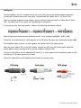
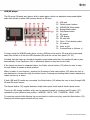
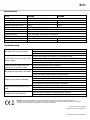
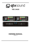
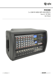
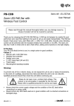
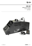
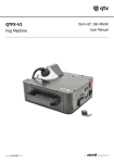
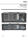
MODEL NUMBER PH SERIES PA HEADS Item ref: 178.734UK, 178.736UK User Manual Caution: Please read this manual carefully before operating Damage caused by misuse is not covered by the warranty Introduction Thank you for choosing a QTX PH series PA Head as part of your sound reinforcement system. This mixer-amplifier is designed to offer high quality, dependable service for mobile and installed systems. Please read this manual fully and follow the instructions to achieve the best results with your new purchase and to avoid damage through misuse. Warning To prevent the risk of fire or electric shock, do not expose any components to rain or moisture. If liquids are spilled on the casing, stop using immediately, allow unit to dry out and have checked by qualified personnel before further use. Avoid impact, extreme pressure or heavy vibration to the case No user serviceable parts inside – Do not open the case – refer all servicing to qualified service personnel. Safety Check for correct mains voltage and condition of IEC lead before connecting to power outlet Speaker leads should be of good quality and have cores which are capable of the power output Do not allow any foreign objects to enter the case or through the ventilation grilles Placement Keep out of direct sunlight and away from heat sources Keep away from damp or dusty environments Ensure adequate air-flow and do not cover cooling vents at the front and rear of the amplifier Ensure adequate access to controls and connections Cleaning Use a soft cloth with a neutral detergent to clean the casing as required Use a vacuum cleaner to clear ventilation grilles of any dust or debris build-ups Do not use strong solvents for cleaning the unit 178.734UK 178.736UK User Manual Input Channel 1. 2. 3. 4. 5. 6. Microphone input (balanced XLR) Line input (unbalanced jack or 2 x RCA) Low frequency EQ control High frequency EQ control Delay effect level Channel output level Master Section 7. 8. 9. 10. 11. 12. 13. 14. 15. 16. Delay effect master level control Delay effect time control Delay effect repeat control AUX input connectors (2 x RCA) Master level output control AUX input level control USB/SD player level control REC output connectors (2 x RCA) Power and level meter LEDs Graphic EQ frequency sliders Note: AUX IN and REC OUT connections (10, 14) are on the rear panel of PH4150 Rear Panel 17. Mains voltage selector 18. Mains power on/off switch 19. IEC mains inlet and fuse holder 20. Speaker outputs (wired parallel) 21. Cooling fan vent 178.734UK 178.736UK User Manual Setting Up Connect speakers via the 2 outputs on the rear panel (20) using good quality speaker leads with 6.3mm jack connectors and twin core cable, recommended no smaller than 2 x 0.5mm² CSA. When connecting speakers to the outputs, ensure that the combined load is no lower than 4 Ohms (4Ω). To make sure of this, check the manufacturer’s information. If connecting more than one speaker, observe the following calculation method. Most PA and sound reinforcement speakers are 8Ω, so we consider that 1/8 + 1/8 = 1/4 Therefore, when connecting 2 x 8Ω speakers to the PH series PA head, the resulting total load is 4Ω. The amplifier output is mono, so each speaker will receive half of the rated output. With the power switch (18) in the Off position, connect the IEC inlet (19) to the mains using the power lead provided, ensuring that the correct voltage is selected (29) Connect a microphone via the balanced XLR input (1) or a line input into the unbalanced jack or RCA connectors (2) for each channel to be used. Wiring for balanced mic and unbalanced line inputs are shown below. 178.734UK 178.736UK User Manual Operation To check an input, ensure that Low and High EQ controls (3, 4) are set to the vertical (12 o’clock) position and the Delay and Level controls (5, 6) are turned fully down. Also, turn down the USB/SD and AUX input level controls (13, 12). Turn the Master volume control (11) down and set all Graphic EQ sliders (16) to the halfway position. Switch the mains power on, turn up the Master volume control (11) part way and gradually increase the Channel output level (6) for the microphone or line input source whilst checking the output through the connected speakers. Alternatively, a USB pen drive or SD card with compressed audio tracks stored can be connected to the USB/SD Audio Player for checking playback through the speakers. More details can be found in the “USB/SD player” section of this manual. Once the sound has been checked through the speakers, increase the Master volume to the required level, ensuring that the LED level meter (15) doesn’t continually reach into the red (+6dB). The red +6dB level meter LED should only ever light briefly on the loudest peaks of the sound (e.g. bass drum beat) and if it lights for anything longer than momentarily, the Channel or Master levels must be reduced until it stops lighting. Adjust the channel output level controls to balance the mix of inputs and if required, adjust the tone of any channel by boosting or cutting the Low and High controls (3, 4) – vertical position is neutral. Furthermore, tone adjustment for the overall mix is available via the master Graphic Equalizer. This section is home to 5 sliders which range from 100Hz to 10kHz centre frequencies. They can be otherwise considered from left to right as Low, Lo-mid, Mid, Hi-mid and High EQ. Halfway up the slider is neutral, top position is 12dB boost and bottom is 12dB cut of that frequency. The PH series PA heads have a built-in Delay section for producing echo effects for vocals or line level inputs. Each channel has a rotary control for Delay level (5), which varies the amount of the input fed to the Delay Section. Turn the master Delay control (7) up part way and then gradually increase the channel Delay level (5) to hear the effect. The Delay effect can be adjusted to have longer or shorter delay time intervals by adjusting the Time control (8) and the number of repeats for the echo effect can be adjusted via the Repeat control (9) The AUX IN control (12) adjusts the volume level of the AUX IN inputs (10) The AUX IN inputs (rear panel for PH4150) are suitable for any line level source. (these 2 x RCA inputs are summed to mono as the amplifier is single channel) The REC outputs (14) are 2 x RCA connectors which carry the main mix output, suitable for recording or linking onto another amplifier. The USB/SD control (13) varies the level of the USB/SD player to the main mix. When not in use, remove USB or SD media, turn down the Master volume control and switch off. Disconnect from the mains if not in use for long periods. 178.734UK 178.736UK User Manual USB/SD player The PH series PA heads each have a built-in audio player which can playback compressed digital audio files stored on either USB memory device or SD card. 22. 23. 24. 25. 26. 27. 28. 29. 30. 31. 32. 33. USB port Folder search buttons USB/SD/Off Mode select Repeat Mode select Play/Pause button EQ select LCD display SD card slot Clock / Track display select IR receiver Mute on/off Previous/Next or Volume +/- To begin using the USB/SD audio player, insert a USB pen drive and/or SD card with compressed audio files stored on it into the USB connector/SD card slot on the front panel (22. 29) Provided that the tracks are stored as standard compressed audio files, the media will start to play automatically. Press Play/Pause (26) to alternately pause or play the current track. If the tracks are stored in separate folders, the Folder search buttons (23) allow the user to step through folders to speed up track selection. Within a folder or root directory, pressing the Previous or Next track buttons (33) allow the user to step backward or forward through the tracks therein. Pressing and holding these buttons adjusts the output volume up or down. If both USB and SD media are connected, the Mode button (24) allows the user to step through USB, SD and Off sound source. The Repeat button (25) toggles between single-track repeat mode and all-tracks repeat mode. There are 6 EQ modes available, which can be stepped through by pressing the EQ button (27) repeatedly to give different tone profiles:– NORMAL - ROCK - POP - CLASSICAL - BASS - LIVE To mute the output whilst allowing the current track to continue to play, press the Mute button (32). Pressing this button again switches off the mute. 178.734UK 178.736UK User Manual Display and Clock Track name and elapsed time information is shown on the backlit LCD display (28). The icons at the top of the display also show the repeat modes and media source selected. This display can be swapped for a 24hr clock display by pressing the Clock button (30). Setting the clock Pressing and holding the clock button makes the hour value flash on the display and the hour value can be changed using the Previous/Next track buttons. Pressing the Clock button again allows the minute value to be changed in the same way. Pressing the Clock button again sets the clock running at the selected time. IR Remote Control The USB/SD player is also supplied with an Infra Red remote control handset. Remove the clear plastic tab from the handset to engage the CR2025 button cell before first use. 34. 35. 36. 37. 38. 39. 40. 41. 42. 43. Player Power on/off button Play/Pause button EQ select USB/SD/Off Mode select Mute on/off Previous/Next track select Volume up/down buttons Repeat Mode select Clock / Track display select Numerical track select Most of the front panel functions of the audio player are duplicated, with a few exceptions. The handset has a numerical keypad (43), allowing for direct track selection – punch in the track number and the track will begin to play after a short pause. Volume up and down buttons are independent of the Previous/Next track select buttons on the handset. The handset also has a Power on/off button to switch the player on or off. 178.734UK 178.736UK User Manual Specifications Model Power supply Channel inputs Output power RMS @ 4Ω Output power RMS @ 8Ω Channel controls Master controls Digital audio player Speaker outputs RCA connectors Dimensions Weight PH4150 PH8200 110/230Vac, 50/60Hz (IEC) 4 x balanced mic/unbalanced line 8 x balanced mic/unbalanced line 150W 200W 100W 130W Low EQ, High EQ, Delay, Level 5-band EQ, USB/SD, AUX, Master USB or SD input with IR remote & backlit LCD display 2 x 6.3mm jack (mono pair), 4 Ohms min. AUX input, REC output 145 x 485 x 240mm 210 x 485 x 270mm 8.55kg 11.50kg Troubleshooting No power LED on control panel Power LED is on but no other LEDs and no output Power and level meter LEDs are lighting but no speaker output No playback from USB or SD media Output is very loud or distorted Output is working but at very low level Feedback with microphones Ensure mains outlet voltage is correct for the unit Check power is switched on at the mains and at the rear panel Check IEC fuse – if blowing fuses, refer to qualified service personnel Check input signals and condition of connection leads Check channel level and EQ controls are not turned fully down Check Master and channel level control is not fully down For digital media, check that files are standard compressed format Check output connections to speakers Check that speakers are in good working order Check that files are standard compressed audio format Check USB/SD level control is not turned fully down Check the volume setting within the audio player Check level of input signal is not too high Reduce channel level and EQ settings Ensure Hi-Z line level input(s) not connected via XLR Check AUX level control and reduce if necessary Check input audio source level is not too low Ensure low impedance line or mic signal is not connected via jack Increase channel level control and EQ settings if turned down Face microphone away from speakers and monitors Reduce channel level control and/or EQ level(s) Disposal: The “Crossed Wheelie Bin” symbol on the product means that the product is classed as Electrical or Electronic equipment and should not be disposed with other household or commercial waste at the end of its useful life. The goods must be disposed of according to your local council guidelines. Errors and omissions excepted. Copyright © 2014. AVSL Group Ltd. 178.734UK 178.736UK User Manual