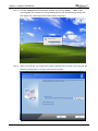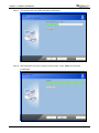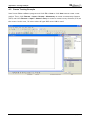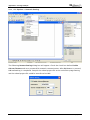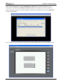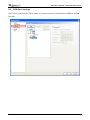
1
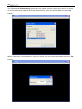
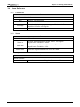
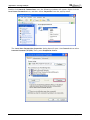
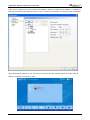
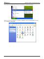
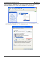
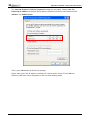
Table of Contents
Chapter 1 Introduction................................................................................. 1-1
1.1 eRemote Remote Control Software....................................................................... 1-1
1.2 Supported Models................................................................................................ 1-1
1.3 System Requirement ............................................................................................ 1-2
Chapter 2 Software Installation .................................................................... 2-1
2.1 eRemote Setup .................................................................................................... 2-1
2.1.1 Software Installation ..................................................................................... 2-1
Chapter 3 Working with eRemote ................................................................. 3-1
3.1 Update Firmware ................................................................................................. 3-1
3.2 Start eRemote ...................................................................................................... 3-2
3.3 Connection .......................................................................................................... 3-2
3.4 Menu Reference ................................................................................................... 3-5
3.4.1 Connection................................................................................................... 3-5
3.4.2 Zoom............................................................................................................ 3-5
3.4.2 Help ............................................................................................................. 3-5
Appendix A
Testing Example....................................................................... A-1
A.1 Networking Settings ............................................................................................ A-1
A.2 Create Testing Example ....................................................................................... A-4
Appendix B
Upload / Download via Ethernet ............................................... B-1
B.1 Configuration Settings ......................................................................................... B-1
B.2 COM Port Settings................................................................................................ B-3
B.3 Compile and Upload / Download Screen & Recipe................................................ B-8
Revision July, 2010
i
Table of Contents
About this Manual…
User Information
Be sure to store this manual in a safe place.
Due to constantly growing product range, technical improvement and alteration or changed
texts, figures and diagrams, we reserve the right of this manual contained information change
without prior notice.
Coping or reproducing any part of this manual, without written consent of Delta Electronics
Inc. is prohibited.
Technical Support and Service
Welcome to contact us or visit our web site (http://www.delta.com.tw/industrialautomation/)
if you need any technical support, service and information, or, if you have any question in
using the product. We are looking forward to serve you needs and willing to offer our best
support and service to you. Reach us by the following ways.
ASIA
JAPAN
DELTA ELECTRONICS, INC.
DELTA ELECTRONICS (JAPAN) INC.
TAOYUAN Plant/
Sales Office/
31-1, SHIEN PAN ROAD, KUEI SAN
DELTA SHIBADAIMON BLDG.
INDUSTRIAL ZONE TAOYUAN 333, TAIWAN
2-1-14 SHIBADAIMON, MINATO-KU,
TEL: 886-3-362-6301
TOKYO, 105-0012, JAPAN
FAX: 886-3-362-7267
TEL: 81-3-5733-1111
FAX: 81-3-5733-1211
NORTH/SOUTH AMERICA
EUROPE
DELTA PRODUCTS CORPORATION
DELTRONICS (NETHERLANDS) B.V.
Sales Office/
Sales Office/
P.O. BOX 12173
DE WITBOGT 15, 5652 AG EINDHOVEN,
5101 DAVIS DRIVE,
THE NETHERLANDS
RESEARCH TRIANGLE PARK, NC 27709,
TEL: 31-40-259-2860
U.S.A.
FAX: 31-40-259-2851
TEL: 1-919-767-3813
FAX: 1-919-767-3969
ii
Revision July, 2010
Chapter 1 Introduction
1.1 eRemote Remote Control Software
eRemote is a PC software used to help the customers view and check the same screen shown
on HMI at the production site, and control the manufacturing process via Ethernet. No matter
where you are, remote controlling is not an arduous task at all.
1.2 Supported Models
The supported models for eRemote Remote Control Software are listed in the table below.
Series
Model Name
Remark
DOP-AE57BSTD
DOP-AE57GSTD
DOP-AE Series
DOP-AE57CSTD
DOP-AE80THTD1
DOP-AE10THTD1
DOP-B Series
Revision July, 2010
DOP series Extension Ethernet
Module, DOP-EXLNHJ1AE is
required when using eRemote
with DOP-AE series HMI
product.
DOP-B10E615
1-1
Chapter 1 Introduction
1.3 System Requirement
Below are the system requirements to comply with the operating environment of eRemote:
Hardware / Software
System Requirement
CPU
Pentium 4, 2GHz or greater is recommended
Memory
1GB and above is recommended
Hard Disk
Capacity: 50MB and above
Monitor
Support resolution: 1024 × 768 or higher full-color display.
Printer
Printer compatible with Windows® 2000 & Windows® XP
Operation System
Windows 2000/WindowsXP/Windows Vista/Windows7
1-2
Revision July, 2010
Chapter 2 Software Installation
2.1 eRemote Setup
In this chapter, it will introduce general functions of eRemote with Windows. The users can
use it to design what they want. Detail information for each function will be discussed in the
following chapters.
2.1.1
Software Installation
To start the eRemote setup, please refer to the following steps:
Step 1. Please start-up your computer to Windows 2000/WindowsXP system.
Revision July, 2010
2-1
Chapter 2 Software Installation
Step 2. Execute setup.exe from Windows taskbar by clicking “Start” > “Run”. After
pressing OK, the system will setup automatically and the following dialog box
will appear for selecting the desired display language.
Step 3. After pressing OK, the system will setup automatically and the users will get the
following dialog box to choose destination location.
2-2
Revision July, 2010
Chapter 2 Software Installation
To select the default directory
C: \Program Files\Delta Industrial Automation\DOP eRemote 1.0, click Next>
for the next step. Setup will install in the directory indicated in the Destination
Directory box at the bottom of the dialog box.
To select a directory other than the default directory, click Browse. A list of
available directories appears. Highlight the desired directory for the Delta
eRemote and click OK, then Next> for the next step.
If necessary, click < Back button to take you back through Setup dialog boxes
one by one.
Step 4. After pressing Next, the following dialog box will appear and ask the users to
select the installation software, i.e. DOP eRemote. Then click Install button to
start DOP eRemote installation.
Revision July, 2010
2-3
Chapter 2 Software Installation
Step 5. The system will start DOP eRemote Installation.
Step 6. DOP eRemote has been installed successfully. Press Close to finish the
installation.
2-4
Revision July, 2010
Chapter 3 Working with eRemote
Before using eRemote, the users need to update HMI firmware. Please ensure to read the
following instructions fully so that the users could understand how to update HMI firmware
correctly.
3.1 Update Firmware
Remember to update the firmware before using eRemote. To select this function, click Start >
Programs > Delta Industrial Automation > HMI > DOP eRemote 1.0 > Update Firmware
Tool.
After clicking Update Firmware Tool, the following dialog box will appear for the users to
select the communication interface (the default setting is USB driver). Press Update button to
update HMI firmware automatically.
Revision July, 2010
3-1
Chapter 3 Working with eRemote
3.2 Start eRemote
To start eRemote, click Start > Programs > Delta Industrial Automation > HMI > DOP
eRemote 1.0 > eRemote.
3.3 Connection
After starting eRemote, click Connection > New from menu bar to create a new connection.
3-2
Revision July, 2010
Chapter 3 Working with eRemote
The following IP Address Setup dialog box will appear, and the system will search and show
all of the connecting HMIs via Etherent automatically. Select the desired HMI and press OK
button.
Before connection, the password is required. Please enter the correct password and press OK
button.
Revision July, 2010
3-3
Chapter 3 Working with eRemote
After entering the correct password, the system will start the connection automatically. After
the connection is successfully established, the users can monitor and control HMI screens on
the computer screen.
3-4
Revision July, 2010
Chapter 3 Working with eRemote
3.4 Menu Reference
3.4.1
Connection
Function
Create Remote Control Connection
New
Create a new connection
Close
Close the current connection
Language
Exit
3.4.2
Select the display language. It supports Traditional Chinese,
Simplified Chinese and English.
Exit the eRemote
Zoom
Function
Determine the view of the eRemote screen
Zoom in
Increase the magnification of the screen. The largest
magnification available is 300%.
Zoom out
Reduce the magnification of the screen. The smallest
magnification available is 25%.
Zoom reset
3.4.3
Reset the magnification of the screen to 100%.
Help
Function
About eRemote
About
Revision July, 2010
Show the various items of legal information of eRemote.
3-5
Chapter 3 Working with eRemote
This page intentionally left blank.
3-6
Revision July, 2010
Appendix A Testing Example
Before creating testing example, make sure to change the upload and download option
(Options > Configuration) on Screen Editor first. The default setting of upload and download
is via USB. If the users need to use Ethernet, please change the default setting by referring to
Appendix B.
A.1 Networking Settings
Ensure to observe the following instructions to complete PC networking settings before
eRemote operation.
Power on PC and start Windows. Click Start > Programs, point to Control Panel, and then
select Network Connections.
Revision July, 2010
A-1
Appendix A Testing Example
Double-click Network Connections icon, the following windows will appear. Right-click the
Local Area Connection icon, and then select Properties from the pop-up menu.
The Local Area Connection Properties dialog box will open. Use General tab to select
Internet Protocol (TCP/IP). Then, press Properties button.
A-2
Revision July, 2010
Appendix A Testing Example
The Internet Protocol (TCP/IP) Properties dialog box will open. Choose Use the
following IP address and enter the IP address numbers of the PC into the field of IP
address and Subnet mask.
Then, press OK button to finish the settings.
Please note that if the IP address numbers of subnet masks of the PC and HMI are
different, HMI may not be displayed in the list when finding node.
Revision July, 2010
A-3
Appendix A Testing Example
A.2 Create Testing Example
Start Screen Editor software program and click File > New or click New icon to create a new
project. Then, click Element > Input > Button > Momentary to create a momentary element
($0.0) and click Element > Input > Numeric Entry to create a numeric entry element ($10) on
the screen. In this case, 10 inches color AE type DOP series HMI is used.
A-4
Revision July, 2010
Appendix A Testing Example
Click Options > Configuration and use Communication tab to select Ethernet and complete
HMI networking settings shown as the figure below. Then, press OK button to finish the
settings.
Revision July, 2010
A-5
Appendix A Testing Example
Next, click Options > Network Setting.
The following Remote Setting dialog box will appear. Check the check box before Enable
eServer/Remote and set a password for network communication. After OK button is pressed,
HMI networking is completed. Compile the edited project file at the end of the programming
and the edited project file could be transferred to HMI.
A-6
Revision July, 2010
Appendix A Testing Example
Then, start the eRemote and click Connection > New from menu bar to create a new
connection. The following IP Address Setup dialog box will appear, and the system will
search and show all of the connecting HMIs via Etherent automatically. Select the eRemote
and press OK button.
At this time, the users are able to monitor and control HMI screens on the computer screen.
Revision July, 2010
A-7
Appendix A Testing Example
This page intentionally left blank.
A-8
Revision July, 2010
Appendix B Upload / Download via Ethernet
B.1 Configuration Settings
The default setting of upload and download on Screen Editor is via USB. If the users need to
use Ethernet, please activate Screen Editor and select Options > Configuration to access the
configuration options and change the upload and download setting.
Revision July, 2010
B-1
Appendix B Upload / Download via Ethernet
In Configuration dialog box, change the default setting of upload and download to Ethernet.
Then, press OK to complete the setting.
B-2
Revision July, 2010
Appendix B Upload / Download via Ethernet
B.2 COM Port Settings
If the users choose to use DHCP mode, it is not necessary to set Ethernet IP address in COM
Port tab.
Revision July, 2010
B-3
Appendix B Upload / Download via Ethernet
If the users choose to use user-defined IP address, please set Ethernet IP address in COM Port
tab and ensure that the domain name is the same as the IP address of the personal computer.
After Ethernet IP address is set, the users can enter into the system menu to verify if the IP
address is written correctly or not.
B-4
Revision July, 2010
Appendix B Upload / Download via Ethernet
Then, observe the following instructions to complete PC networking settings.
Power on PC and start Windows. Click Start > Programs, point to Control Panel, and then
select Network Connections.
Revision July, 2010
B-5
Appendix B Upload / Download via Ethernet
Double-click Network Connections icon, the following windows will appear. Right-click the
Local Area Connection icon, and then select Properties from the pop-up menu.
The Local Area Connection Properties dialog box will open. Use General tab to select
Internet Protocol (TCP/IP). Then, press Properties button.
B-6
Revision July, 2010
Appendix B Upload / Download via Ethernet
The Internet Protocol (TCP/IP) Properties dialog box will open. Choose Use the
following IP address and enter the IP address numbers of the PC into the field of IP
address and Subnet mask.
Then, press OK button to finish the settings.
Please note that if the IP address numbers of subnet masks of the PC and HMI are
different, HMI may not be displayed in the list when finding node.
Revision July, 2010
B-7
Appendix B Upload / Download via Ethernet
B.3 Compile and Upload / Download Screen & Recipe
After completing PC networking settings, compile the editing program immediately. When
compile operation is performed successfully, choose Upload Screen & Recipe or Download
Screen & Recipe next.
B-8
Revision July, 2010
Appendix B Upload / Download via Ethernet
Then, the following dialog box will appear.
The users can check the box before Auto Search, and the system will detect the connecting
HMI automatically.
When the connecting HMI is found, press Start button, and the system will start to upload or
download the screen data via Ethernet immediately.
Revision July, 2010
B-9
Appendix B Upload / Download via Ethernet
This page intentionally left blank.
B-10
Revision July, 2010