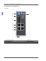
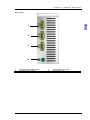
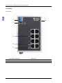
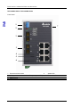
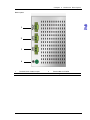
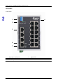
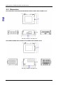
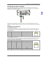
1
Industrial Automation Headquarters
Delta Electronics, Inc.
Taoyuan Technology Center
No.18, Xinglong Rd., Taoyuan City,
Taoyuan County 33068, Taiwan
TEL: 886-3-362-6301 / FAX: 886-3-371-6301
Asia
Delta Electronics (Jiangsu) Ltd.
Wujiang Plant 3
1688 Jiangxing East Road,
Wujiang Economic Development Zone
Wujiang City, Jiang Su Province, P.R.C. 215200
TEL: 86-512-6340-3008 / FAX: 86-769-6340-7290
Delta Greentech (China) Co., Ltd.
238 Min-Xia Road, Pudong District,
ShangHai, P.R.C. 201209
TEL: 86-21-58635678 / FAX: 86-21-58630003
Delta Electronics (Japan), Inc.
Tokyo Office
2-1-14 Minato-ku Shibadaimon,
Tokyo 105-0012, Japan
TEL: 81-3-5733-1111 / FAX: 81-3-5733-1211
Delta Electronics (Korea), Inc.
1511, Byucksan Digital Valley 6-cha, Gasan-dong,
Geumcheon-gu, Seoul, Korea, 153-704
TEL: 82-2-515-5303 / FAX: 82-2-515-5302
DVS Series Unmanaged
Industrial Ethernet
Switches User’s Manual
Delta Electronics Int’l (S) Pte Ltd.
4 Kaki Bukit Ave 1, #05-05, Singapore 417939
TEL: 65-6747-5155 / FAX: 65-6744-9228
Delta Electronics (India) Pvt. Ltd.
Plot No 43 Sector 35, HSIIDC
Gurgaon, PIN 122001, Haryana, India
TEL : 91-124-4874900 / FAX : 91-124-4874945
Americas
Delta Products Corporation (USA)
Raleigh Office
P.O. Box 12173,5101 Davis Drive,
Research Triangle Park, NC 27709, U.S.A.
TEL: 1-919-767-3800 / FAX: 1-919-767-8080
Delta Greentech (Brasil) S.A.
Sao Paulo Office
Rua Itapeva, 26 - 3° andar Edificio Itapeva One-Bela Vista
01332-000-São Paulo-SP-Brazil
TEL: 55 11 3568-3855 / FAX: 55 11 3568-3865
Europe
Deltronics (The Netherlands) B.V.
Eindhoven Office
De Witbogt 15, 5652 AG Eindhoven, The Netherlands
TEL: 31-40-2592850 / FAX: 31-40-2592851
V 0.01.01.001
*We reserve the right to change the information in this manual without prior notice.
2013-11-07
www.deltaww.com
DVS Series Unmanaged Industrial Ethernet Switches
User’s Manual
Table of Contents
Chapter 1 Overview
1.1 Features ..........................................................................................1-2
1.2 Package Checklist ...........................................................................1-2
Chapter 2 Hardware Description
2.1 Panel Layout ...................................................................................2-2
2.2 Dimension .....................................................................................2-24
2.3 LED Indicators ...............................................................................2-25
2.4 Wiring the Redundant Power Inputs ..............................................2-26
2.5 Wiring the Alarm Contact ...............................................................2-27
2.6 Ethernet Interface ..........................................................................2-27
2.7 DIP Switch Setting.........................................................................2-28
Chapter 3 Installation
3.1 DIN-Rail Mounting ...........................................................................3-2
3.2 Wall Mounting..................................................................................3-3
Chapter 4 Functional Description
4.1 Auto MDI/MDI-X Connection ...........................................................4-2
4.2 Auto-Negotiation and Speed Sensing ..............................................4-2
4.3 Stored and Forward .........................................................................4-2
4.4 Addresses Capability and Learning .................................................4-2
4.5 Quality of Service and VLAN Tagging..............................................4-2
4.6 Broadcast Control............................................................................4-2
i
ii
Chapter 1
Overview
Table of Contents
1.1
1.2
1-1
Features ....................................................................................................1-2
Package Checklist .....................................................................................1-2
D VS Ser ies In dus tr ia l Ethe rne t Sw itches
FCC Interference Statement
This equipment has been tested and found to comply with the limits for a class B digital device,
pursuant to part 15 of the FCC Rules. These limits are designed to provide reasonable protection
against harmful interference in a residential installation.
This equipment generates radio frequency signal and, if not installed and used in accordance with
the instructions, may cause harmful interference to radio communications. However, there is no
guarantee that interference will not occur in a particular installation. If this equipment does cause
harmful interference to radio or television reception, which can be determined by turning the
equipment off and on, the user is encouraged to try to correct the interference by one or more of the
following measures:
---Reorient or relocate the receiving antenna.
---Increase the separation between the equipment and receiver.
---Connect the equipment into an outlet on a circuit different from that to which the receiver is
connected.
---Consult the dealer or an experienced radio/TV technician for help.
CE Declaration of Conformity
The DVS series switches are CE certificated products, they could use in any kind of the
environments under CE environment specification. For keeping more safe application, we strongly
suggest to use the CE-compliant industrial enclosure products.
1.1 Features
Thank you for purchasing the DVS Unmanaged Industrial Ethernet Switches. The DVS series
switches including 5, 8, and 16-port smart switches. Except the DVS-005I00, The DVS series
switches are equipped with the intelligent alarm function, and allow the wide range of operating
temperature (-40 to 75℃). The DVS series switches are designed to support the application in any
rugged environment and comply with UL, CE and FCC standards.
High Performance Network Technology
.10/100Bas-T(X) (RJ45), 100Base-FX (SC/ST-Type Single/Multi mode)
.IEEE 802.3/802.3u/802.3x
.Auto negotiation speed
.Auto MDI/MDI-X
Industrial Grade Reliability
.Relay output port support power failure, port break alarm
.Redundant dual DC power inputs
Robust Design
.DVS-005I00/ 008I00/ 005I00A/ 008I00A operating temperature range is from -10 to 60℃, other
DVS switches could extend operating temperature from -40 to 75℃.
.IP40, high-strength aluminum case
.Support DIN-Rail and Wall mounting
1.2 Package Checklist
DVS switches include the following items, if there are any of these items missing or damaged,
1-2
Ch ap te r 1 O ver view
please contact your customer service representative for assistance.
.Delta DVS Unmanaged Ethernet Switch
.Instruction Sheet
.Wall mounting Plate
.Protective Caps for unused RJ45 ports
1-3
D VS Ser ies In dus tr ia l Ethe rne t Sw itches
MEMO
1-4
Chapter 2
Hardware Description
Table of Contents
2.1
2.2
2.3
2.4
2.5
2.6
2.7
Panel Layout .............................................................................................2-2
Dimension ...............................................................................................2-24
LED Indicators.........................................................................................2-25
Wiring the Redundant Power Inputs ........................................................2-26
Wiring the Alarm Contact.........................................................................2-27
Ethernet Interface....................................................................................2-27
DIP Switch Setting...................................................................................2-28
2-1
D VS Ser ies In dus tr ia l Ethe rne t Sw itches
2.1 Panel Layout
DVS-005I00
Front Panel
5
1
2
3
4
1
2
3
2-2
Power LED
Ethernet port
Speed LED
4
5
LINK/ACT LED
Series model name
Chapter 2 Har dware Descr iption
Bottom panel
1
2
1
Terminal Block of PWR
2
Grounding screw
2-3
D VS Ser ies In dus tr ia l Ethe rne t Sw itches
DVS-G005I00A
Front Panel
5
1
2
3
4
1
2
3
2-4
Power LED
Ethernet port
Speed LED
4
5
LINK/ACT LED
Series model name
Chapter 2 Har dware Descr iption
Bottom panel
1
2
1
Terminal Block of PWR
2
Grounding screw
2-5
D VS Ser ies In dus tr ia l Ethe rne t Sw itches
DVS-005W01
Front Panel
1
6
2
3
4
5
1
2
3
2-6
Event alarm DIP Switch
LED (ALARM / PWR1 / PWR2)
Ethernet port
4
5
6
Speed LED
LINK/ACT LED
Series model name
Chapter 2 Har dware Descr iption
Bottom panel
1
2
3
4
1
2
Terminal block of alarm output
Terminal Block of PWR1
3
4
Terminal block of PWR2
Grounding screw
2-7
D VS Ser ies In dus tr ia l Ethe rne t Sw itches
DVS-005W01-MC01 / DVS-005W01-SC01
Front Panel
1
7
2
3
4
5
6
1
2
3
4
2-8
Event alarm DIP Switch
LED (ALARM / PWR1 / PWR2 / Fiber port speed LED)
Fiber Ethernet port
Ethernet port
5
6
7
Speed LED
LINK/ACT LED
Series model name
Chapter 2 Har dware Descr iption
Bottom panel
1
2
3
4
1
2
Terminal block of alarm output
Terminal Block of PWR1
3
4
Terminal Block of PWR2
Grounding screw
2-9
D VS Ser ies In dus tr ia l Ethe rne t Sw itches
DVS-008I00
Front Panel
5
1
2
3
4
1
2
3
2-10
Power LED
Ethernet port
Speed LED
4
5
LINK/ACT LED
Series model name
Chapter 2 Har dware Descr iption
Bottom panel
1
2
1
Terminal Block of PWR
2
Grounding screw
2 - 11
D VS Ser ies In dus tr ia l Ethe rne t Sw itches
DVS-G008I00A
Front Panel
5
1
2
3
4
1
2
3
2-12
Power LED
Ethernet port
Speed LED
4
5
LINK/ACT LED
Series model name
Chapter 2 Har dware Descr iption
Bottom panel
1
2
1
Terminal Block of PWR
2
Grounding screw
2-13
D VS Ser ies In dus tr ia l Ethe rne t Sw itches
DVS-008W01
Front Panel
1
6
2
3
4
5
1
2
3
2-14
Event alarm DIP Switch
LED (ALARM / PWR1 / PWR2)
Ethernet port
4
5
6
Speed LED
LINK/ACT LED
Series model name
Chapter 2 Har dware Descr iption
Bottom panel
1
2
3
4
1
2
Terminal block of alarm output
Terminal Block of PWR1
3
4
Terminal Block of PWR2
Grounding screw
2-15
D VS Ser ies In dus tr ia l Ethe rne t Sw itches
DVS-008W01-MC01 / DVS-008W01-SC01
Front Panel
1
7
2
3
4
5
6
1
2
3
4
Event alarm DIP Switch
LED (ALARM / PWR1 / PWR2 / Fiber port speed LED)
Fiber Ethernet port
Ethernet port
2-16
5
6
7
Speed LED
LINK/ACT LED
Series model name
Chapter 2 Har dware Descr iption
Bottom panel
1
2
3
4
1
2
Terminal block of alarm output
Terminal Block of PWR1
3
4
Terminal Block of PWR2
Grounding screw
2-17
D VS Ser ies In dus tr ia l Ethe rne t Sw itches
DVS-008W01-MC02 / DVS-008W01-SC02
Front Panel
1
7
2
3
3
4
5
6
1
2
3
4
Event alarm DIP Switch
LED (ALARM / PWR1 / PWR2 / Fiber port speed LED)
Fiber Ethernet port
Ethernet port
2-18
5
6
7
Speed LED
LINK/ACT LED
Series model name
Chapter 2 Har dware Descr iption
Bottom panel
1
2
3
4
1
2
Terminal block of alarm output
Terminal Block of PWR1
3
4
Terminal Block of PWR2
Grounding screw
2-19
D VS Ser ies In dus tr ia l Ethe rne t Sw itches
DVS-016W01
Front Panel
1
6
2
3
4
5
1
2
3
2-20
Event alarm DIP Switch
LED (ALARM / PWR1 / PWR2)
Ethernet port
4
5
6
Speed LED
LINK/ACT LED
Series model name
Chapter 2 Har dware Descr iption
Bottom panel
1
2
3
4
1
2
Terminal block of alarm output
Terminal Block of PWR1
3
4
Terminal Block of PWR2
Grounding screw
2-21
D VS Ser ies In dus tr ia l Ethe rne t Sw itches
DVS-016W01-MC01 / DVS-016W01-SC01
Front Panel
1
7
2
3
4
5
6
1
2
3
4
Event alarm DIP Switch
LED (ALARM / PWR1 / PWR2 / Fiber port speed LED)
Fiber Ethernet port
Ethernet port
2-22
5
6
7
Speed LED
LINK/ACT LED
Series model name
Chapter 2 Har dware Descr iption
Bottom panel
1
2
3
4
1
2
Terminal block of alarm output
Terminal Block of PWR1
3
4
Terminal Block of PWR2
Grounding screw
2-23
D VS Ser ies In dus tr ia l Ethe rne t Sw itches
2.2 Dimension
DVS-005I00/DVS-008I00/G005I00A/G008I00A /005W01/005W01-MC01/005W01-SC01
145.3(H) x 45(W) x 108.7(D) mm
DVS-008W01/008W01-MC01/008W01-SC01/008W01-MC02/008W01-SC02
145.3(H) x 75(W) x 108.7(D) mm
2-24
Chapter 2 Har dware Descr iption
DVS-016W01/016W01-MC01/016W01-SC01
145.3(H) x 75(W) x 108.7(D) mm
2.3 LED Indicators
DVS-005I00 / DVS-008I00 / G005I00A / G008I00A
LED
Color
Status
Description
ON
The power is supplied normally.
PWR
Green
OFF
The power is not supplied.
ON
The port is connected at a speed of 100 Mbps.
100M
Orange
OFF
The port is connected at a speed of 10 Mbps or disconnected.
Green
ON
The port is connected at a speed of 1000Mbps.
10/100/1000M Orange
ON
The port is connected at a speed of 100Mbps.
OFF
The port is connected at a speed of 10 Mbps or disconnected.
The Network communication connection has been
ON
established.
LINK/ACT
Green Blinking The data is being transmitted.
The Network communication connection has not been
OFF
stablished.
DVS-005W01 / DVS-008W01 / DVS-016W01
LED
Color
Status
Description
ON
The communication is interrupted, or there is a power failure.
ALARM
Red
The communication is not interrupted, or there is no power failure.
OFF
The DIP switch is not enabled.
ON
The power is supplied normally.
PWR1
Green
OFF
The power is not supplied.
ON
The power is supplied normally.
PWR2
Green
OFF
The power is not supplied.
ON
The port is connected at a speed of 100 Mbps.
100M
Orange
OFF
The port is connected at a speed of 10 Mbps or disconnected.
ON
The Network communication connection has been established.
LINK/ACT Green
Blinking The data is being transmitted.
2-25
D VS Ser ies In dus tr ia l Ethe rne t Sw itches
LED
Color
LINK/ACT Green
Status
OFF
Description
The Network communication connection has not been stablished.
DVS-005W01-MC01 / DVS-005W01-SC01 / DVS-008W01-MC01 / DVS-008W01-SC01 /
DVS-008W01-MC02 / DVS-008W01-SC02 / DVS-016W01-MC01 / DVS-016W01-SC01
LED
Color Status
Description
ON
The communication is interrupted, or there is a power failure.
ALARM
Red
The communication is not interrupted, or there is no power failure.
OFF
The DIP switch is not enabled.
ON
The power is supplied normally.
PWR1
Green
OFF
The power is not supplied.
ON
The power is supplied normally.
PWR2
Green
OFF
The power is not supplied.
ON
The fiber port is connected at a speed of 100 Mbps.
100M
Green
OFF
The fiber port is not connected.
100M
ON
The port is connected at a speed of 100 Mbps.
Orange
(on the
OFF
The port is connected at a speed of 10 Mbps or disconnected.
RJ45 port)
LINK/ACT
Green
ON
Blinking
OFF
The Network communication connection has been established.
The data is being transmitted.
The Network communication connection has not been stablished.
2.4 Wiring the Redundant Power Inputs
Except the DVS-005I00, the DVS series switches are equipped with two sets of DC input (PWR1 /
PWR2). Both sets of DC input can be connected to a wide range of power sources (12 to 48VDC). If
one power source fails, the other live source can work as a backup to ensure that the machine
operates normally.
Step 1: Insert the negative and positive DC wires into the terminal block, and make sure that the
positive DC wire is connected to V1+ or V2+, and that the negative DC wire is connected to 0V.
Step 2: To prevent the loose DC wires , tighten the wire clamp screws on the terminal block
connector with the flat-blade screwdriver.
Step 3: Insert the plastic terminal block connector into the terminal block receptor on the DVS series
switch.
2-26
Chapter 2 Har dware Descr iption
2.5 Wiring the Alarm Contact
The alarm contact is a dry relay. If one of the two power sources fails or the communication is
interrupted, the contact will turns from an “OPEN” circuit to a “CLOSED” circuit. The relay can be
connected to a 5A/24VDC power source.
A typical way to use the alarm is to connect the Alarm circuit to a warning light or buzzer in the
control room. The light or buzzer could be set up to turn on when any of the above two conditions is
detected.
2.6 Ethernet Interface
10/100Base-T(X) Connection
The 10/100Base-T(X) ports of the DVS series switches are used to connect to Ethernet. They can
support MDI (NIC–type) and MDI-X (HUB/Switch-type) modes, the pin definition of the Ethernet
cable is as follows.
PIN
MDI Mode Definition
MDI-X Mode Definition
1
Tx+
Rx+
2
TxRx3
Rx+
Tx+
6
RxTx10/100/1000Base-T Connection
The 10/100Base-T(X) or 10/100/1000Base-T ports of the DVS series switches are used to connect
to Ethernet. RJ45 ports support MDI (NIC–type) and MDI-X (HUB/Switch-type) modes, the pin
definition of the Ethernet cable is as follows.
10/100Base-T(X)
1000Base-T
PIN
MDI Mode
MDI-X Mode
PIN
1
Tx+
Rx+
TP0+
2
TxRxTP03
Rx+
Tx+
TP1+
4
n.c.
n.c.
TP2+
5
n.c.
n.c.
TP26
RxTxTP17
n.c.
n.c.
TP3+
8
n.c.
n.c.
TP3-
2-27
D VS Ser ies In dus tr ia l Ethe rne t Sw itches
100Base-FX Connection
The products are US FDA CDRH AEL Class 1 product.
The output signal of the fiber port will damage the eyes
Do not look directly at the fiber port.
In your fiber connection application, the RX port of DVS switches must connect to the TX port of the
other fiber device and the TX port of DVS switches must connect to the RX port of the other fiber
device.
Fiber Optic
Wavelength
Cable
Max TX
power
Min TX
RX
Optical
Distance
power
Sensitivity
Budget
-20dBm(1)
11dBm(1)
1310nm
-14dBm
-31dBm
2~5km
MultiMode
-22.5dBm(2)
8.5dBm(2)
1310nm
-8dBm
-15dBm
-31dBm
16dBm
30km
SingleMode
Remark : (1) 62.5/125um fiber optic cable. (2) 50/125um fiber optic cable
IEEE standard transmission distance is 2km for 50/125um or 62.5um fiber optic cable. Actually, up
to 2~5km distance is possible before dissipating the optical power budget of 8.5dBm~11dBm to a
value below the Rx sensitivity. And 30km distance is possible before dissipating the optical power
budget of 16dBm to a value below the Rx sensitivity.
2.7 DIP Switch Setting
ON:
OFF:
2-28
After the corresponding switch of the port is enabled, when
the communication is interrupted, the relay will form a
“CLOSED” circuit, and the alarm LED will be on.
After the corresponding switch of the port is disabled, when
the communication is interrupted, the relay still forms an
“OPEN” circuit, and the alarm LED will not be on.
Chapter 3
Installation
Table of Contents
3.1
3.2
DIN-Rail Mounting .....................................................................................3-2
Wall Mounting............................................................................................3-3
3-1
D VS Ser ies In dus tr ia l Ethe rne t Sw itches
3.1 DIN-Rail Mounting
The attached metal DIN-Rail plate should already be fixed to the rear panel of DVS switch when you
get it. If you want to mount DVS switch with DIN-Rail, please make sure that the stiff metal spring is
towards the top, as shown in the following figures,
Mounting
Step 1: Hook the upper end of the DIN clip of the DVS series switch on the DIN-Rail.
Step 2: Lightly push the DVS series switch toward the DIN-Rail until they contact each other closely.
Removal
Step 1: Insert the flat-blade screwdriver into the DIN clip and pull the DIN clip downward.
Step 2: Pull the DVS series switch, and you can remove it from the DIN-Rail.
3-2
Ch ap te r 3 Ins ta lla tion
3.2 Wall Mounting
Step 1: Insert the wall mounting bracket into the slot on the rear panel of the DVS series switch, and
tighten the screw on it, as shown in the diagram below.
Step 2: Place the wall mounting bracket in an appropriate position, and tighten the two screws on
the bracket and the DIN clip.
Please install the DVS with necessary airflow applied, and sufficient space around it to
allow heat dissipation.
3-3
Chapter 4
Functional Description
Table of Contents
4.1
4.2
4.3
4.4
4.5
4.6
4-1
Auto MDI/MDI-X Connection .....................................................................4-2
Auto-Negotiation and Speed Sensing........................................................4-2
Stored and Forward...................................................................................4-2
Addresses Capability and Learning ...........................................................4-2
Quality of Service and VLAN Tagging........................................................4-2
Broadcast Control......................................................................................4-2
D VS Ser ies In dus tr ia l Ethe rne t Sw itches
4.1 Auto MDI/MDI-X Connection
The Auto MDI/MDI-X function let users connect DVS switches’ 10/100Base-T(X) ports to any kind of
Ethernet device. You don’t need to pay attention to the type of Ethernet cable being used for the
connection. This means that you can use either a straight-forward cable or cross-over cable to
connect DVS switches to Ethernet device.
4.2 Auto-Negotiation and Speed Sensing
All of DVS switch’s RJ45 Ethernet ports could independently support auto-negotiation for speeds in
the 10BaseT and 100Base-T(X) modes, with operation according to the IEEE 802.3u standard. It
means that it could support some ports operating in 10 Mbps and the others ports operating in
100Mbps in the same time.
Auto-negotiation happens when a RJ45 cable connection is made, and then each time a LINK is
enabled, DVS switches advertises its capability for using either 10Mbps or 100Mbps transmission
speeds, with the device at the other end of the cable expected to similarly advertise. Depending on
what type of device is connected, this will result in agreement to operate in a speed of either
10Mbps or 100Mbps.
4.3 Stored and Forward
DVS switches could support the packet size between 64 bytes to 1522 bytes. They could store the
traffic packets when the buffer of the receiver device in the other size of the internet line is full. DVS
switches could store the packages until the receiver device could process the new package, DVS
switches will restart to send the stored package to the receiver.
4.4 Addresses Capability and Learning
DVS switches has address learning engine to learn the source address of ingress frames. Up to 8K
MAC addresses and port number mappings can be stored in the address database. When a new
MAC address found that is not in the MAC address mapping database. DVS switches could
self-learning the message of the MAC address and place it into the MAC database. It means that
DVS switches could automatically support more internet devices in the application.
4.5 Quality of Service and VLAN Tagging
DVS switches has another feature that is different from other unmanaged switches, that is DVS
switches could support high speed and non-blocking to transfer the packets with VLAN tagging or
the 4 traffic classes QoS packet. The priority from high to low is 7 to 0. The 4 sets priorities are “7,6”,
“5,4” , “3,0”, “2,1”. The highest level priorities are 7and 6 for the application as RIP and OSPF
protocol routing updated. The priority “5,4” is for the delay-sensitive application as video and audio
application. The priority “3,0” is for the control-load application as streaming multi-media and
business critical traffic application. The priority “2,1” is the lowest priority for the application that don’t
need any application setting. This feature could let the network application be more flexible and it
will not limit the networks setting cause of the packet types.
4.6 Broadcast Control
When some network device work abnormal, it maybe will send out to many broadcast packets and it
maybe will paralysis the Ethernet traffic. DVS-008/016W series have Broadcast control function, this
feature could limit the broadcast packet traffic under the 10% full speed packet traffic and it could
avoid the abnormal broadcast packet to paralysis the Ethernet traffic and the user has more stable
Ethernet environment.
4-2