1
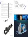
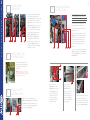
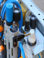
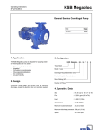
FOK
MACHINES
FIBRE OPTIC CABLE BLOWING MACHINE USER’S BOOK
fokmachine.com
FIBER OPTIC CABLE BLOWING MACHINES
ABOUT US
Our company ever since its incorporation in the
telecommunication sector has been operating the machine.
Our company since its establishment until the superior service
quality and customer satisfaction continues to be one of the
leading companies.
Fiber Optic Cable Blowing Machine (FOK), a single supplier and
telecommunication in TURKEY. Turk Telekom, Turkcell and the
VODAFONE’S FOK uses subcontractors in Turkey. According to
information from users FOK in 1999 to the present continuous
revisions are made more useful.
Our services include; machine spare parts manufacturing, a
complete machine manufacture, stockpiling of machine parts,
components or systems required the development of machines
with the development of R & D activities are.
Our Vision
Profitable and sustainable growth to ensure long-term customer
and employee satisfaction, and satisfaction as well as aims.
Our Mission
High standards, quality service in the time of our customers
to maximize customer satisfaction and respect the rights. Our
products, solutions, after sales service we provide our customers
with reliability and high business ethics as the first choice to
be a company that creates value for our employees and our
customers.
Our Quality Policy
The fact that customer satisfaction
as a priority action in this direction is
to provide products and services.
For this reason,
• Complying with the terms of the
quality management system, to
sustain activity.
• Ethics, values, respect and team
spirit, and the potential to increase
customer satisfaction.
• Improve the competitiveness of the
industry by continuously improving
staff satisfaction and education.
• Our employees, customers, suppliers
long-term commitment to our
organizations and institutions to
increase non-cooperation.
• The provisions of relevant laws
and standards to export to the
framework.
fokmachine.com
FOK
MACHINES
FIBRE OPTIC CABLE BLOWING MACHINE USER’S BOOK
1
FIBRE OPTIC CABLE BLOWING MACHINE USER’S BOOK
2
USER’S
BOOK
3
SELECTING AND
LOCATING CABLE SEALS
1
1
SELECTING AND LOCATING
CABLE SEALS
2
SETTING AXIS FOR CABLE
DIAMETER
3
PREPARING
PULLEYS
4
LOCATING PRE-INSTALLED
DUCT AND CABLE
5
MAKING AIR CONNECTIONS
COMING FROM AIR COMPRESSOR
6
PRESSURE GAUGES, PRESSURE
VALUES AND SETTING PRESSURES
7
USING SHOCK
LUBRICANT
8
USING DIRECTION
CONTROL VALVE
9
USING PALETTE
CONTROL VALVE
10
11
FOK MAINTENANCE
INSTRUCTIONS
SAFETY RULES
12
TRANSPORTING
MACHINE
13
CORRECTION OF
FAULTS
14
TOOLS GIVEN WITH
MACHINE
Figure 1
Figure 2
Figure 3
Figure 4
Firstly measure cable diameter with callipers (figure 1). The selected cable seal’s inside diameter (figure 2)
must be same with cable’s outside diameter and it must work slippery on cable (figure 3) not to let air leak.
Cut cable seals as you see on figure 4.
NOTE: You must inform us your cable diameter that you will install with your FOK order.
Canals of the selected cable seals must
locate to install way of cable. If not ,we can
not use compressed air productive which
comes from compressor (figure5-1).
Touch faces of black o-rings with cable
seals must be cutted angular (figure5-2)
Figure 5
1
2
FIBRE OPTIC CABLE BLOWING MACHINE USER’S BOOK
4
5
2
SETTING AXIS FOR
CABLE DIAMETER
Figure 6-a
1
Figure 6-b
LOCATING PRE-INSTALLED
DUCT AND CABLE
4
2
Axis of the machine must be set, when
the cable diameter is changed to make
productive blowing. Locate the cable
you will blow into machine as seen
on figure 6-a to set axis. Loosen bolts
(Number 3.4 and 5) and set on same
level cable axis in machine (No: 1) with
touch face (No: 2) between up and
down exit box parts. Then setting axis
press bolts (3, 4, 5, numbers on figure 6-c
/ 6-d) to fix axis for your cable.
2
1
3
Figure 8
Loosen bolts (No: 2, 3 on figure 8) firstly to
assemble Duct to machine and then leave
the upper part (No: 1) . Drive duct until the
face number 4. Then put the upper part
(No: 1) on cable and press bolts (No: 2, 3)
to finish duct assemble Locate cable into
machine as shown on figure 8.
NOTE: Selecting cables, setting cable axis, preparing
pulleys are done when the cable diameter is changed.
4
NOTE: If you inform our company about your cable
diameter before you buy machine, machine axis
will be setted by our company. When you will blow
different cablediameter, you will have to set axis as we
explained up wrench set will be given with machine.
Figure 6-c
3 4
3
5
PREPARING
PULLEYS
Pulleys on figure enable the cable to go
into the machine on axis easily. Pulleys’
distance is set by bolts (No: 1, 2 on Figure
7) for cable diameter. Pulleys’ distance
must be closed, ıf not, cable can get out
from sides and break.
1
2
Figure 7
MAKING AIR CONNECTIONS
COMING FROM AIR COMPRESSOR
5
Figure 6-d
NOTE: Selecting cables, setting cable axis, preparing
pulleys are done when the cable diameter is changed.
Figure 9-a
2
1
Figure 9-b
3
Figure 9-c
Connect 1’’air hose to machine with quick connection which comes from
air compressor. Quick connection main body is assembled on machine
as you see figure on 9-a-1. Quick connection moving part is given with
machine as you see in figure 9-a-2. Assemble quick connection moving
part to the machine as you see in figure 9-b. Connect air hose to the part
3 in figure 9-b. Then assemble parts as you see in figure 9-c.
FIBRE OPTIC CABLE BLOWING MACHINE USER’S BOOK
6
7
PRESSURE GAUGES, PRESSURE
VALUES AND SETTING PRESSURES
6
1
2
Figure 10
3
1
2
3
B- SETTING AIR MOTOR PRESSURE
LUBRICATION STYLE
1
Duct Pressure Value; Duct blowed in
world standards must have minimum
10,5 bar (You must see this value on
gauge shown in figure 10-1) to blow your
cable. If not, you can’t blow your cable.
Air Motor Pressure; You must see
6.5-7 bar on gauge (figure 10-2) when
you are blowing. If you work on higher
values this will cause your motor
pulleys to be damaged and your air
motors will break down.
2
4
5
Figure 13
3
6
7
Figure 14
1
2
A- SETTING PALETTE PRESSURE
You can set piston pressure
(figure11-1) on palettes with using
regulator (figure12-2) and you can
control pressure on gauge (figure12-3).
Do not increase pressure value too
much if you increase it you can damage
your cable and air motors.
Figure 11
Figure 12
1
2
3
The reservoir (figure 13-4) takes moisture of
pressurized air which comes from compressor.
Use tap (figure 15-1) to discharge collected
moisture. You must do this operation not to let
rust the parts of air motors.
Put oil for air motors to reservoir (figure 13-5). And
use screw (figure 15-2) to re-fill it. This is necessary
to lubricate bearings of air motors.
When the blue stopper opened (figure 14-7)
lubrication for air motors will be closed
Pallettes Pressure Value; Pneumatic
piston supplies pallette pressure. This
system prevents the wear on your
cable between pallettes. You must
set this pressure value with checking
weather conditions. Your cable mustn’t
skid between pallettes in normal
conditions this value range must be
between 2-4 bars.
NOTE: Setting air engine pressure and palette
pressure is explained on the next page. There is no
pressure setting for DUCT
Use the mechanism (figure 13-1)to set pressure of
air motors and control on qauge (figure13-2).
Air motors must work between 6.5-7 bar.
Figure 15
Use screwdriver (figure14-3) to set the amount of
oil for air motors.
Current amount of oil is one drop in one minute.
You can see drop in (figure 14-6).
NOTE: Our FOK is ready to install cable after making the
configurations we stated as number 1,2,3,4,5,6 in earlier pages.
We can start to install our cable by using direction control valve.
FIBRE OPTIC CABLE BLOWING MACHINE USER’S BOOK
8
USING SHOCK
LUBRICANT
7
FOK MAINTENANCE
INSTRUCTIONS
10
To reduce friction between cable and
duct put special oil (lubricant) into
reservoir (Figure 16-1-1). You may see the
closed position for lubricant valves on
figure16-2. To let oil into duct open valve
(figure 16-2-2) then open-close valve in
a short time (figure 16-3-3) This quick
open-close move will let oil into duct.
1
Figure 16
5
4
1
2
2
3
3
6
You may check duct lubricant from
indicator (figure 16-3-6) to re-fill
reservoir,open valve (figure 16-1-4)
and discharge pressurized air.Then
this discharge close valve. Then open
reservoir lid. (figure 16-1-5) and put
lubricant oil and close lid again tightly
until there is no air leak
To maintain air motors, open oil set screw
until end (Figure 18-1) and run motors 30-35
secs on this position. This operation supplies
bearing lubrication for air motors and parts.
This operation must be repeated in every
evening after the work ends, if not the
moisture collected in motors will cause the
bearings to rust.
Figure 19
Figure 18
1
2
1
USING DIRECTION
CONTROL VALVE
8
9
You can regulate fibre optic cable
direction and speed (0-60m/min) by
moving direction control valve to
right or left.
2
3
The foreign objects entering into reservoir
(figure 18-2) causes to the filter be blocked.
This changes its colour and its shape. You
must change this filter before this case
occurs, if not air pressure yield will be less
and you will have problems about the
machine.
You can see the demontaging of air filter on
figure 19. Firstly open reservoir (figure 19-1)
and nut (figure 19-2) then you can take air
filter (figure 19-3)
1
2
NOTE: You must use stop position when you are
changing the direction.If you pass the opposite
direction directly and don’t stop on stop position this
will damage the gears of air motors.
Figure 22
3
Figure 17
USING PALETTE
CONTROL VALVE
9
Palettes can join or leave with buttons on
figure 18-1 and figure 18/2. Push or pull button
on figure 18-2 while pushing button 18-1.You
can set movement velocity of upper palettes
by using valves on figure 18-3.
Figure 18
1
2
3
Figure 20
Figure 21
Put out cable seals
(figure20-1) and o-rings
(figure20-2) to make care of
exit box (figure 20). Clean
their slots with diesel oil
and brush. If cable seals
and orings are beaten,
change them otherwise
there will be air leak.
Locate your cable in
to machine as shown
in figure 22. Pallettes
must press to cable and
pallettes mustn’t touch
each other. If they touch,
this means your pallettes
are worned away. Pallettes
must be changed.
1
Figure 23
If the blowing area is muddy, mud
can go into the palettes of the
machine, you may clean mud with
pressured water and using holes as
you may see on figure 22 and 23.
FIBRE OPTIC CABLE BLOWING MACHINE USER’S BOOK
10
11
11
SAFETY
RULES
If there is something
happens unusual on
machine push emergency
button to get out pressurised
air from machine then close
compressor quickly.
If there is something
happens unusual on
machine push emergency
button to get out pressurised
air from machine then close
compressor quickly.
Do not open cover
before evacuating
air on box.
Do not open water tap and
oil jar before evacuating
air on machine
You must check quick
connection before giving air
to machine. Take up quick
connection part as you see in
figure 24 to check it. Do not
use if it is coming up.
Close nuts correctly before
giving air on machine. If
nuts and bolts are beaten
changethem with new ones.
13
CORRECTION
OF FAULTS
If your machine can not catch cable and palettes skids on cable ,it means that your palettes are damaged
and needs to change or palette pressure is low. (Look 6/6-A)
If cable exit box squeeze cable it means that cable seals are false chose correct cable seals. (Look 1)
If there is oil or air leaking on exit box palettes side it means that your cable seals are false or montaged
false direction. (Look 1)
Figure 24
If there is air leaking on exit box, clean surfaces of exit box and change o-rings. (Look 10)
12
TRANSPORTING
MACHINE
If your machine is working hardly while you are blowing cable, it means that your ducts air pressure can be
less, you need to increase your air pressure which is coming from compressor. It must be minimum 12 bar /
10.5 metercup / minute. (Look 6)
If your cable blowing machine is working but you can not blow cable in ducts it means that your ducts can
be plugged. You need to solve the problems in ducts. (Look 15-1)
If palettes of cable blowing machine is not turning it means that bearings are damaged because of slogging
or bearings are rusted because of being in wet situation. You must send machine for maintenance.
If your air motor is not not turning it means that bearings of air motor are damaged you need to send
machine to maintenance. (Look 6-b)
Figure 25
Figure 26
After taking out in box. Carry cable
blowing machine as on figure 25.
Carry cable blowing machine as
on figure 26.
IMPORTANT NOTE: Take out air on machine
before carring machine.
If your air motor is not not turning it means that gears are damaged you need to change gears. You must
send machine for maintenance.
If your air pressure on motors are reducing while you are cable blowing it means that your air filter is
plugged or damaged you need to change it. (Look 10)
FIBRE OPTIC CABLE BLOWING MACHINE USER’S BOOK
12
13
14
TOOLS GIVEN
WITH MACHINE
15
CONDITIONS FOR FIBRE OPTIC CABLE BLOWING MACHINE PRODUCED BY KOSMAK MACHINE BUILDING,
INDUSTRY&TRADE CO. THAT YOU HAVE TO CHECK ON WORKING AREA BEFORE YOU START TO WORK.
USE OF MACHINE TOOLS
1.
Socket wrench arm set (“T” arm)
1 Qty
2.
Socket wrench arm set mid part (Long: 25 cm)
1 Qty
3.
Socket wrench (16-13)
1 Qty
4.
Open-End wrenchs (8-9 / 10-11)
1 Qty
5.
Allen wrench (5mm, 6mm)
1 Qty
6.
Screw driver (3x80)
1 Qty
7.
Stationery knife
1 Qty
8.
Special air lubricant oil
1 Qty
9.
O-Ring (Ø95x5)
1 Qty
10. Ø 3,5 O-Ring 50 cm
1 Qty
11. Ø 4 O-Ring 50 cm
1 Qty
12. Ø 8 Air pipe 100 cm
1 Qty
13. Ø14 Air pipe 2 mt
1 Qty
14. Ø 16 Air pipe 50 cm
1 Qty
A) CABLE FOR 4 FOY-6 FOY-12 FOY-24 FOY;
C) CABLE FOY 96 FOY;
a- Exit box cable seal slot b- Cable seal 17x32x10
c- Oil felt
a- Exit box cable seal slot
b- Cable seal 22x32x8
c- Oil felt
1 Qty
10 Qty
3 Qty
1) DUCT CONTROL
USE NATURAL GAS PIPE (DIA:25MM,LENGTH:1.5m ) BOTH SIDE CLOSED TO CONTROL DUCT.THIS PIPE
MUST PAS ALL ALONG IN YOUR DUCT.
NOTE: We set axis
line of FOK with the
information of cable
diameter before
sending the machine.
We send 10 pieces
cable seals, 1 piece
cable seal slot and 3
pieces of felts with
machine for your cable
diameter. You can see
cable diameter groups
under, but if you inform
us your cable diameter
this will be better.
2) MACHINE CONTROL
MONTAGE THE MACHINE TO PIPE AND LET PRESSURIZED AIR IN,AFTER YOU CHECKED THE SUITABILITY
OF YOUR DUCT. WHEN PRESSURIZED AIR WENT OUT FROM THE END OF DUCT, YOU MUST SEE THESE
VALUES: AIR MOTOR PRESSURE: 6 BAR /// PISTON PRESSURE:2-4 BAR /// DUCT PRESSURE: 10.5 BAR
(MACHINE AXIS MUST BE SET TO RUN)
3) WORKING CONTROL
YOU MUST TRY TO STAY IN SAME LEVEL AS FAR AS POSSIBLE DUCT,MACHINE AND FIBRE OPTIC CABLE
YOU MUST HAVE THESE VALUES WHEN YOU ARE RUNNING MACHINE: AIR MOTOR PRESSURE: 6 BAR ///
PISTON PRESSURE:2-4 BAR DUCT PRESSURE:10-11 BAR. CHECK OIL DROP VALUE THAT YOU NEED FOR
AIR MOTORS ON AIR LUBRICANT(2-3 DROPS/MIN) YOU MUST DO SHOCK LUBRICATION IN EVERY 150
METRES YOU INSTALLED. YOU MUST LEAVE INSIDE OF AIR MOTORS OILY AFTER YOU USE THE MACHINE
.TO DO THIS:LOOSEN THE OIL SET SCREW ON PREPERATION AIR LUBRICANT AND INCREASE THE SPEED
OF OIL FLOW AND RUN MACHINE 3-4 MINS IN THIS POSITION.
1 Qty
10 Qty
3 Qty
B) CABLE FOR 36 FOY-48 FOY-60 FOY;
D ) CABLE FOR 144 FOY-192 FOY;
a- Exit box cable seal slot
b-Cable seal 18x30x8,5
c- Cable seal 20x30x8
d- Oil felt
a- Exit box cable seal slot
b- Cable seal 28x40x10
c- Oil felt
1 Qty
10 Qty
10 Qty
3 Qty
WORKING
LAND TERMS
1 Qty
10 Qty
3 Qty
15
FIBRE OPTIC CABLE BLOWING MACHINE USER’S BOOK
14
EC DECLARATION OF
CONFIRMITY
KÖ SMA K MA KİN A İN ŞAAT TAAHHÜT SANAYİ VE TİCARE T LİM İTED ŞİRKE T İ
According to Machinery Directive 2006/42/EEC
Manufacturer:
KÖSMAK Makine İnşaat Taahhüt San. ve Tic. Ltd. Şti.
Küçük Körfez Sanayi Sitesi 201 Blok No:4 KOCAELİ / TURKEY
Declaration:
Herewith we declare under our own responsibility that the products
designated below
Products:
KOS type of fiber optic cable blowing machine
are manufactured in accordance with the EC Directives
Directives:
Managing Director
Machinery Directive 2006/42/EEC including their amendments.
Harmonised Standards: TS EN ISO 12100, EN 60204-1
Kocaeli , 2014
FIBER OPTIC CABLE BLOWING MACHINES
FIBER OPTIC CABLE BLOWING MACHINES
Kör fez Küçük Sanayi Sitesi 13. Blok
No:8 41040 İzmit, Kocaeli, TURKEY
0090 533 778 9941
fokmachine.com
[email protected]