1
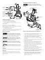
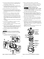
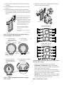
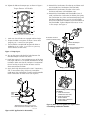
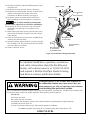
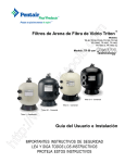
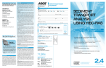
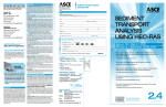
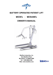
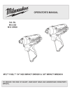
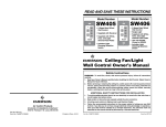
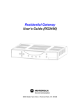
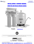
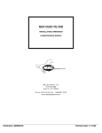
Heater Insulation Kit
Sta-Rite Pool/Spa Group
293 Wright Street, Delavan, WI 53115
North America: 800-752-0183, FAX 800-582-2217
International: 262-728-5551, FAX: 262-728-4461, TELEX: ITT 4970245
www.sta-ritepool.com
Union City, TN • Delavan, WI • Mississauga, Ont. • Murrieta, CA
© 2003, Sta-Rite Industries, Inc.
Printed in U.S.A.
S430 (Rev. 2/14/03)
Servicing Procedure (See Figure 1):
Heavy parts; can cause personal injury.
When lifting, use all proper precautions for the weights
involved.
1/2" Insulation
Blanket
Combination Gas Control Valve OFF
1" Insulation
OF
F
NO
Turn Clockwise
and press down
to turn off gas.
NT
VE
Manual/Gas Valve OFF
S
ES
PR
B
TA
OT
PIL
Power
Flameholder Insulation
Cap
Condensate
Evaporator
NO
1" Insulation
OFF
VEN
T
SS
PRE
TAB
OT
PIL
1/2" Insulation
Blanket
Remove Water Pressure
Switch to help Manifold
Drain
3120 1197
Tools/Parts Required
Drain Inlet/Outlet
Manifold
Flat Screwdriver, Phillips Screwdriver
1/4” and 3/8” Socket Sets with Extenders
Sockets needed:1/4”, 5/16, 11/32, 7/16, 1/2, 9/16, 7/8
Rubber Mallet
Torque Wrench calibrated in Inch-Lbs.
High Temperature RTV (600° F. Cont.; 700° F. Intermittent)
Flame Holder/Adapter Plate Gaskets
(2 - Part No. 42001-0065)
14” & 12” Pipe Wrenchs (1 Each) or 2 Channel-Lock Pliers
Optional: Lifting Gear capable of handling 150 Lbs.
Inlet
2704 1196
Outlet
Open
Drain Cock(s) and Plugs
OPEN
Close Isolation Valves
Figure 1: Isolate and Drain Heater; Disconnect Power
Safety Precautions:
1. Turn off the filter pump and all electrical power to the
heater. Close the external Manual Gas Valve.
2. If the heater is below the water level of the pool, close
the isolation valves to avoid draining the pool.
3. Remove the drain plug under the manifold and drain
the heater.
4. While the heater is draining, remove the upper left and
upper right jacket halves.
5. Remove the switch covers on both sides of the manifold and unplug the wires from the Automatic Gas
Shutoff, the High Limit Thermostat, and the Thermistor
(See Figure 2, Key No. 1). If necessary, disconnect the
Water Pressure Switch and remove it.
6. Disconnect exhaust vent from indoor units.
7. Disconnect the gas pipe at the external union between
the heater and the external manual gas valve.
8. Disconnect the incoming electrical wires at the junction
box and cut the wire tie holding the Wiring Harness to
the Lower Enclosure (See Figure 2, Key No. 2).
9. Disconnect the inlet and outlet unions and move the
heater enough to allow removal of the manifold
adapter and the inlet/outlet manifold as a unit (See
Figure 2, Key No. 3).
Risk of electrical shock, fire or explosion.
Disconnect all power to the heater and close the external
manual gas valve at start of this procedure. Check for gas
leaks with a soapy water solution after reassembly.
Risk of carbon monoxide poisoning from
indoor units if exhaust vent joints are not sealed. Check
all vent joints for leakage after reassembly.
Heavy parts; can cause personal injury.
When lifting, use all proper precautions for the weights
involved.
Uncured RTV sealants can cause eye irritation. Follow manufacturer’s instructions when using RTV
sealants.
Location
The Insulation is located inside the Combustion Chamber.
Function
The insulation increases the thermal efficiency of the
heater and prevents overheating of parts outside the combustion chamber.
2
10. Unscrew the bolts that attach the manifold adapter to
the tube sheet and remove the manifold adapter and
the inlet/outlet manifold as a unit.
11. Carefully disconnect all three metering tubes from the
Combustion Air Blower Assembly (1 to the Combination
Gas Control Valve, 2 to the Air Flow Switch).
12. Remove the bolt from the Gas Piping Clamp.
13. Unplug all wires to the Control Box. Unscrew three
nuts and remove the Control Box, the Heat Shield, and
the Membrane Pad and Cover as a unit (See Figure 2,
Key No. 4).
14. Unscrew the four nuts holding the Blower Adapter
Plate to the top of the Combustion Chamber and
remove the Combustion Air Blower, the Igniter, the
Combination Gas Valve and associated piping and the
Blower Adapter Plate as a unit (See Figure 2, Key No.
5). Remove the Flameholder and Flameholder Cone (if
used).
NOTICE: BE CAREFUL not to break or crack the igniter
– it is fragile!
15. Unscrew the nuts holding the Combustion Chamber
top to the Combustion Chamber body.
16. Unscrew 4 hold-down nuts from the hangers supporting the Combustion Chamber.
17. Wrap a shop rag around each hanger, one at a time (be
careful; it’s sharp) and hammer down on the Lower
Enclosure while lifting the hanger by the shop rag. This
will lift the hanger up off of the hold-down bolt.
18. Lift the Combustion Chamber out of the Lower
Enclosure.
20. With a mallet and screwdriver, go around the
Combustion Chamber cover tapping up until the RTV
separates and releases the Combustion Chamber cover.
Be careful not to damage the Combustion Chamber.
21. Remove the Combustion Chamber cover.
California’s Proposition 65 lists
Refractory Ceramic Fibers heated to 1800° F or higher
as a possible human carcinogen. See the warning box
on Page 6 for further information. Call 1-800-752-0183
for a Material Data Safety Sheet (MSDS).
22. Remove the top insulation, the Heat Exchanger Coil,
the Condensate Evaporator, the Bottom Insulation, and
the metal spacer from the Combustion Chamber. Do
not remove the RTV that seals the manifold mounting
plate to the combustion chamber.
23. Clean up the Combustion Chamber, the Combustion
Chamber cover, and the Spacer. Be sure to completely
remove all RTV from the Combustion Chamber and
Combustion Chamber top.
24. Reinstall the clean spacer in the Combustion Chamber.
Install one 1/2” white Insulation Blanket on top of the
spacer and one piece of 1” “M” insulation on top of the
Blanket. Make sure that the insulation is centered in the
Combustion Chamber.
NOTICE: Model SR/SRC200 heaters built before 1/1/98
require two 1/2” Insulation Blankets.
Flameholder
Heavy parts; can cause personal injury.
When lifting, use all proper precautions for the weights
involved.
19. Cut the RTV all the way around the top of the
Combustion Chamber with a screwdriver.
1/2" Top
Blanket
5
Flameholder
Insulation
Cap (Tape
to bottom of
Flameholder)
1" Top
Insulation
4
Condensate
Evaporator
2
1" Bottom
"M" Insulation
1/2" Bottom
Blanket
Spacer
3
3122 1197
1
Figure 3: Correct order for installation of insulation.
Figure 2: Removal of major sub-assemblies
3
25. Install the new Condensate Evaporator on top of the
insulation.
26. Clean the tubesheet and O-Ring sealing surfaces (see
Figure 4).
27. Reinstall the Heat Exchanger Coil on the Insulation.
Pull the Heat Exchanger Coil and the Bottom Insulation
forward together to align with the mounting plate (see
Figure 5).
28. Install the manifold and manifold bolts. See Figure 6
for long and short bolt positions.
1. Clean the tube sheet and O-ring
sealing surface with a nylon brush,
then brighten the tube sheet
surface with 320 grit emery cloth.
NOTE: When cleaning, be careful
not to push the tube sheet into the
combustion chamber. If you do,
thread a couple of bolts into it
and pull it back in place.
Models SR200/SRC200
Short Bolt Placement
2. Brush off all dust and debris
with a brush and wipe it down
with a cloth.
3. Apply silicone grease (supplied)
to O-Rings.
2-3/4"
2-3/4"
*
*
4067 0901
2-1/2"
2-1/2"
Figure 4: Clean the Tube Sheet and O-Ring sealing surfaces thoroughly as described above.
*
A. Center Insulation
in lower enclosure.
Add Evaporator Plate.
Evaporator
Plate
Insulation
B. Center Heating
Coil on Insulation.
*
C
2-3/4"
2-3/4"
Heating
Coil
Models SR400/SRC400
Short Bolt Placement
2-3/4"
Do not
disturb
RTV in these areas
*
*
2-1/2"
C. Slide Coil, Insulation,
and Evaporator Plate
into Manifold Mounting
Plate.
2-3/4"
Tube
Sheet
Lower
Enclosure
D. No Gaps between insulation
and Tube Sheet
2-1/2"
*Hand-tighten all long bolts; then tighten indicated bolts enough to
allow short bolts to engage.
Here and Here
• Install O-rings on tube ends; install manifold.
• SR/SRC200 and SR/SRC400: Tighten all long bolts
HAND TIGHT; then tighten the bolts next to the short
bolts a little more with a wrench.
• Insert and start the two short bolts until they engage
three or four threads, then tighten all bolts according to
the normal torque pattern shown on Page 5.
• SR/SRC333: These models use long bolts only. Tighten
all bolts HAND TIGHT; then tighten according to the
normal torque pattern shown on Page 5.
4076 1001
Figure 5: Align bottom insulation and Heat Exchanger
Coil as shown.
Figure 6: Install bolts as shown.
4
29. Tighten the bolts to the torque spec as shown in Figure 7.
33. Reinstall the Combustion Chamber top and fasten with
nuts on studs from Combustion Chamber body.
34. Reinstall the Combustion Chamber in the Lower
Enclosure and fasten with hold-down nuts.
35. Reinstall the Flameholder and Flameholder Cone (if
used), and then the Combustion Air Blower, the Igniter,
the Combination Gas Valve and associated piping and
the Blower Adapter Plate as a unit; use new gaskets.
Be sure to reinstall the Insulation Cap on the bottom of
the Flameholder. Tighten Adapter Plate nuts to 70-80
in.-lbs. torque. See Figure 9.
Torque Pattern - All Models
9
8
5
4
1
2
3
6
7
10
75-115 in.-lbs./8.4-12.9 N-m
Reinstall Control Box
and Heat shield Assembly
1. Make sure that all bolts are engaged and hand tight.
2. Torque the bolts in sequence as shown. Some noise
(popping, etc.) is normal as you tighten.
3. Go around the manifold and retighten the bolts as
needed to 75-115 in-lbs. (8.4-12.9 N-m) (you may
have to do this several times).
Flameholder/Adapter
Plate Gasket
Flameholder/Combustion
Chamber Gasket
Figure 7: Torque Specs.
30. Turn on the water and check for leaks between the
Manifold Adapter and the Tube Sheet.
31. Install one piece of 1” top Insulation on top of the Heat
Exchanger and one 1/2” Insulation Blanket over the top
Insulation. Make sure that the insulation is centered on
the coil so that an equal number of heater coil fins
shows around the insulation.
32. Apply fresh High Temperature RTV (600°F Continuous,
700° F. Intermittent rating) all the way around the
inside top of the Combustion Chamber and the outside
of the Combustion Chamber cover (see Figure 8).
3123 1197
1
dapter
2
r/Combustion
asket
Apply RTV
here
and
here.
3123 1197
3
At reassembly, connect tubing
as shown:
1. From Air Inlet Port to
Combination Gas Valve;
2. From Air Inlet Port to
Air Flow Switch;
3. From bottom of Blower to
Air Flow Switch.
Figure 9: Make sure new gaskets are in place when
reassembling combustion chamber.
Apply RTV bead all the way around
both Combustion Chamber and Cover.
3140 0198
Figure 8: RTV Application For Reassembly
5
36. Reinstall Control Box and Heat Shield assembly; fasten
with three nuts.
37. Reconnect the water pressure switch (if necessary).
38. Reconnect the metering tubes from the Air Flow Switch
and the Combination Gas Control Valve to the
Combustion Air Blower Assembly (see Figure 9).
39. Reconnect exhaust vent pipe and seal with RTV or
epoxy according to vent manufacturer’s instructions.
White to White
Green (Ground)
to
Green (Ground)
Black to Black
Risk of carbon monoxide poisoning. Make
sure that entire exhaust vent is sealed after reinstallation.
40. Reconnect all wiring. See Figure 10 for Junction-box
connections, and see Page 7 for complete wiring
schematic.
41. Before starting the heater, test for gas leaks from piping
and around Combustion Chamber cover with a soapy
water solution.
42. Check for water leaks at unions and at manifold flange
(where it joins the tube sheet).
43. Reinstall jacketing and test heater by running it through
one complete cycle. Test for exhaust leaks from exhaust
vent pipe while cycling heater.
44. Heater is ready for service.
Bonding
Wire
Wiring Harness
to Control Box
Wire into bottom
of Junction-box
in Flexible Conduit
View From Above
(Interior)
Figure 10: Junction Box Wiring Connections
For detailed installation, operation, maintenace
and safety information about the Sta-Rite pool
heater, call customer service at 1-800-752-0183
and request a Sta-Rite Pool/Spa Heater Training
and Service manual, publication S5066.
Prolonged exposure to the ceramic fiber insulation in
the combustion chamber may cause cancer. May also
cause temporary eye, skin, or respiratory tract irritation.
Avoid breathing fiber particulates and dust.
Wear a NIOSH/MSHA approved respirator, loose, long sleeved clothing, eye protection, and gloves when working with
or around insulation. Wash work clothes separately. Rinse washing machine after use.
For first aid:
Eyes: Flush with water.
Skin: Wash with soap and water.
If swallowed: Do not induce vomiting. Get medical attention if gastrointestinal symptoms develop.
If inhaled: Get to fresh, clean air.
If any of the irritations above persist, seek medical attention immediately.
For additional product information or for a Material Safety Data Sheet (MSDS), call
1-800-752-0183
6
CONNECTION DIAGRAM
AGS Switch
Air Flow Switch
Stack Flue Sensor
Extra Switch 1
Gas Valve
Y/R
Y/BL
Y/O
Hi-Limit Switch
Y/W
Y
Pressure Switch
Y
Y
Y
Y
O
O
BL
O
BL
W
O
THERMISTOR
ES1
OPERATING CONTROL
AFS
GAS
Y
Y
Y
Y
MEMBRANE PAD
CONNECTION
AGS
SFS
J6
1
HLS
FS
PS
24VAC
R
VAL
TH
IND
GND
24VAC
Y
BR
BR
PR
PR
R
JMP3
9
W
Y/W
VERSION 1 PAD
1
External Control Interface Circuit
Disabled, Heater Membrane Pad
Enabled
CONTROL CENTER
SPA CONTROL
Spa Line
Common Line
Pool Line
External Control Interface
JMP3
BK
Y
BK
1
F1
24
F2 VAC
IGNITION CONTROL
MODULE
DIAGNOSTIC INDICATOR
JMP3
Y
Y
24VAC
1
FC1
FC2
S1/
120 L1 L2
External Control Interface
Circuit Enabled, "Pool On"
and "Spa On" Keys Disabled.
"OFF" Key on Membrane
Pad Remains Functional.
S2
SEC
TH IND VAL GND
PRIM
GY
Y/W
GY
120VAC
Y/O
Y/BL
W
BK
Y/R
120VAC
IGNITER
BLOWER
Y/W
120VAC
GND
MOT
BK
G
TRANS
L1
F1
F
I
R
E
M
A
N
S
TRANS
FL
S
W
I
T
C
H
L2
BM
1
J6
BK
GND
Y
W
W
W
GND
9
JUNCTION BOX
GROUND (GND)
W
G
BK
120VAC (HOT)
W
If cable from Membrane Pad
NEUTRAL (NEU)
is a 6-Conductor Cable, connect
it to pins 4 - 9 on Operating
NOTICE: If, while there is 120VAC connected to the heater, you touch
Control Board as shown.
either 120VAC terminal with any 24VAC wire that is connected to the
control board (including the Fireman's Switch jumper), you will
immediately destroy the control board and void the warranty.
Replace jumper with leads to
Fireman's Switch (field installed)
3661 0200
7
1
2
3
4
5
6
3125 1197
REPAIR PARTS LIST
Key
No.
1
2
3
4
5
6
Part
Description
Flameholder Insulation Cap
1/2” Blanket
1” Top Insulation
Condensate Evaporator
1” “M” Insulation
1/2” Blanket*
Qty.
Part
No.
1
1
1
1
1
1
42001-0075
42001-0071
42001-0070
42001-0065
42001-0072
42001-0073
* Model SR/SRC200 heaters built before 1/1/98 use 2 of
Part No. 42001-0073.
8