1
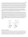
LYNX EAVE MOUNT PATIO HEATER LHEM48 CARE AND USE MANUAL Installation of Lynx Eave Mounted Patio Heater should only be installed by a person knowledgeable about gas appliances TO THE INSTALLER: Please read these instructions completely before installation. Give this manual to the owner. TO THE OWNER: Keep this manual in a safe place for future reference. NOTE: Remote control devices have been pre-initialized and are ready to use. Lynx Professional Grills, 5895 Rickenbacker, Commerce, CA 90040 PH (888) 289-5969 P/N 33535 10/2013 WARNING READ THIS MANUAL CAREFULLY and completely before using your heater to reduce the risk of: 1. Fire 2. Burn hazard, personal injury or property damage 3. Unapproved installation or servicing. THIS PRODUCT IS DESIGNED FOR OUTDOOR USE ONLY. Improper installation, adjustment, alteration, service or maintenance can cause property damage, injury or death. Read this manual thoroughly before installation, use, or servicing of this product. DANGER DANGER IF YOU SMELL GAS: 1. Shut off all gas supply lines to the heater. 2. Extinguish any open flames. 3. If odor continues, keep everyone away from the appliance and immediately call your gas supplier or your fire department. S’IL Y A UNE ODEUR DE GAZ: 1. Coupez l’admission de gaz de l’appariel. 2. Èteindre toute flamme nue. 3. Si l’odeur persiste, èloignez-vous de l’appareil et appelez immèdiatement le fournisseur de gaz ou le service d’incendie. WARNING WARNING • • • DO NOT store or use gasoline or other flammable vapors and liquids in the vicinity of this or any other appliance. An LP cylinder not connected for use shall not be stored in the vicinity of this or any other appliance. • Ne pas entreposer ni utiliser de l’essence ni d’autres vapeurs ou liquides inflammables dans le voisinage de l’appareil, ni de tout autre appareil. Une bouteille de propane qui n’est pas raccordèe en vue de son utilisation, ne doit pas ètre entreposèe dans le voisinage de cet appareil ou de tout autre appareil. WARNING! CALIFORNIA PROPOSITION 65 • • • The burning of gas fuel generates some by-products which are on the list of substances which are known by the State of California to cause cancer or reproductive harm. California law requires businesses to warn customers of potential exposure to such substances. To minimize exposure to the substances, always operate this unit according to the care and use instructions found in this manual. California Proposition 65 lists “Silica, crystalline” which is used in one of the components of the infrared burner, as an agent known to the state of California to cause cancer. i DANGER CARBON MONOXIDE HAZARD This appliance can produce carbon monoxide which has no odor. If not installed, operated, and maintained in accordance with manufacturers instructions, the emissions from this product can cause serious illness or death. Never use this appliance in an enclosed space.. WARNING • Never use dented, rusty or damaged propane cylinders. Never store additional or empty propane cylinders in the vicinity of this or any other appliance. Do not store propane cylinders indoors or on their sides. • Children should NEVER BE LEFT ALONE or unattended in an area where this appliance is located. Install your heater well away from areas where children play. Do not store items, that may interest children, in or around the area of your heater. • Always maintain the required clearances from combustibles as detailed. This heater is designed for outdoor use only. Never use in a garage, building, shed, breezeway, or other enclosed area. Local codes regarding head clearance requirements must be observed. • Certain materials or items, when stored under the heater, will be subject to radiant heat and could be seriously damaged. • Always have an ABC Fire Extinguisher accessible. • Keep any electrical supply cord and the fuel supply hose away from any heated surfaces. Electrical cords should be placed away from walkways to avoid tripping hazard. • Do not repair or replace any part of this appliance unless specifically recommended in this manual. Other service should be performed by a qualified technician. • This appliance must be installed by a professional installer or technician. Be sure that he/she shows you where your gas supply shut-off is located. All gas lines must have a shut-off valve that is readily and easily accessible. If you smell gas, check for gas leaks immediately at the external pipe or hose connections. Check only with a soap and water solution. Never check for gas leaks with an open flame. See section “Checking for Gas Leaks” for further details. • If you are using an LP gas tank, inspect the LP gas supply hose prior to each use of the accessory. If there is evidence of excessive abrasion or wear, or the hose is cut, it must be replaced before using the appliance. • Never remove the grounding prong from any plug, and never use this product with an ungrounded, 2-prong adapter. • THIS MANUAL MUST REMAIN WITH THE PRODUCT OWNER FOR FUTURE REFERENCE. This product complies with ANSI standard Z83.26-2007/ Z83.26a-2008 and CSA 2.37-2007/ CSA 2.37a-2008 and has been tested and approved by Intertek. To obtain replacement parts or service contact: Lynx Professional Grills, 5895 Rickenbacker, Commerce, CA 90040 888-289-5969 ii WARNING 1. 2. This gas appliance and its individual shutoff valve must be disconnected from the gas supply piping system during any pressure testing of that system at test pressures in excess of 1/2 psi (3.5 kPa). This gas appliance must be isolated from the gas supply piping system by closing its individual manual shutoff valve during any pressure testing of the gas supply piping system at test pressures equal to or less than 1/2 psi (3.5 kPa). STATE OF MASSACHUSETTS: 1. 2. 3. Massachusetts requires all gas be installed using a plumber or gas fitter carrying the appropriate Massachusetts license. All permanently-installed natural gas or propane installations require a “T” handle type manual gas valve be installed in the gas supply line to this appliance. This does not apply to portable propane installations using a 20 pound cylinder. WARNING - ELECTRICAL GROUNDING • • • • • • • Product installation must meet local electric codes or, in the absence of local codes, the latest edition of the National Electrical Code ANSI/NFPA No. 70 or the Canadian Electrical Code CSA C22.1. Use only a Ground Fault Interrupter (GFI) protected circuit when plugging in the AC adaptor of this appliance. This appliance is equipped with a low voltage, AC adaptor. All connecting cords must be for outdoor use and contain three prong (grounded) electric plugs for your protection against shock hazard. Cords must have a “W-A” marking, and must be plugged directly into a properly grounded three prong outlet. Never cut or remove the grounding prong from this plug. To protect against electric shock, do not immerse any part of the extension cord or any plugs in water or other liquid. Unplug the AC adaptor from its power source when long periods of time are anticipated for the appliance to be out of use. Do not let the extension cord hang over the edge of a table or touch hot surfaces. Do not operate any outdoor appliance with a damaged cord, plug, or after the appliance malfunctions or has been damaged in any manner. Contact the manufacturer for repair. SPRINKLERS: This appliance must be located at an appropriate distance away from fire sprinklers (4ft min. recommended) to avoid accidental activation of sprinkler. Ethylene glycol or propylene glycol must never be used in fire sprinkler systems where heaters are present, as these substances may become flammable when heated. A fire sprinkler professional must be consulted when heaters are installed where fire sprinklers are present to insure that heaters and fire sprinklers are properly integrated. Specific guidelines can be found in NFPA 13 regarding design and specifications for fire sprinkler systems near heaters. iii TABLE OF CONTENTS- Lynx Eave Mount Patio Heater Important Safety Precautions…………………………………………………….….….i-iii Lynx Eave Mount Patio Heater-Important Features……………………….…….1 Mounting Considerations………………………………………………………………...1-2 Code Requirements…………………………………………………………………………....2 Gas Supply and Connections……………………………………………………..…….2-3 Electrical Supply Specifications and Connections…………………………………3 Mounting the Heater………………………………………………………………..…..…4-8 Making the Gas Connections……………………………………………………….…..8-9 Checking for Gas Leaks…………………………………………………………………..….10 Making the Electrical Connections…………………………………………………....11 Wireless Wall Switch………………………………………………………………………….11 Battery Installation…………………………………………………………………….…11-12 Initializing the Remote Control System..……………………………………...13-14 Basic Operation of Your Heater………………………………………………..…….…14 Touch Screen Remote Control Operation………………………………..…..15-21 Low Battery Indicator/ Replacing the Batteries……………………….……21-22 Pilot Flame Adjustment………………………………………………………………..…..22 Trouble Shooting………………………………………………………………………....23-24 Exploded View Parts Diagram..…………………………………………………....25-26 Warranty Information………………………………………………………………....……27 P age |1 Thank you for your purchase of our LYNX Deluxe Eave Mount Patio Heater. This product has been manufactured with the highest quality materials available, and combines the most advanced, state of the art, internal components with cutting edge, heater design technology . This product is sure to provide you many, many, years of enjoyment and comfort. The design elements of this heater, including its Lynx, signature polished highlights, and slim, attractive appearance, allow it to be mounted, with pride, in highly visible locations of your home. It will most likely architecturally blend and enhance any portion of your home in which you chose to install it. Please read this entire manual before attempting to install or operate your new heater. Features of your Lynx Eave Mount Patio Heater: Manufactured completely from Stainless Steel with welded construction Spark ignition with heat sensing safety pilot Slim, custom profile Attractive, adjustable, heavy duty mounting brackets (extension is made from 6 GA, 3/16” thick stainless). Can be adjusted from 10” to 18” Mounting pivot adjustability from 0 -30 degrees from the horizontal. Allows for a precise direction of heat. Decorative safety grill provides wind resistance and protection from sudden gusts. Convenient, DC operation. Requires no 110V electrical routing for basic installation. Operates with an attractive, wireless, wall mounted, on-off-hi-low switch. Operates additionally with a highly sophisticated, touch screen, remote control device. Remote control provides 6 levels of heat adjustment for NG gas type, and 3 levels for LP gas type. Heat adjustment is viewable as either a digital temperature readout, or as a numerical readout displaying the 6 heat levels. Infrared technology provides a burner that generates up to 35,000 BTU’s of heat. Adjustable down to 27,000 BTU’s (LP) and 24,000 BTU’s (NG) 110 V AC Adaptor included. Optional 12 ft flexible gas line hook-up (works with NG or LP) Optional, wireless, wall mounted timer allows for a timed, worry-free operation. Special considerations should be made when selecting a location for your heater before installation. The most important of which should be a location that will serve to be the most functional and useful in providing heat. Suggested locations would be under an eave, on a wall of an open or partially enclosed patio, or on a fascia. This heater has been thoroughly tested and certified to function during and after mild rain storms, and during mild wind conditions. We would like to point out, however, that by avoiding locations that subject your heater to constant wind or rain exposure, will greatly extend the life or your new heater. Other considerations should be its mounting position in relation to combustible materials. Combustible materials include wood, wood fascias, wood siding, stucco mounted over wood studs, vinyl siding, and drywall. See installation diagrams that reference mounting distances. MOUNTING CONSIDERATIONS Select a location that provides the most functionality. Avoid locations that are prone to direct wind or rain exposure. This heater provides ample heat and large heat adjustability. It does not have to be located at eye level, as, its high output will allow a distant location to still be affective. Do not mount this heater indoors or in a totally enclosed room. It needs air to breath and vent. P age |2 Avoid locations that are in close proximity to combustible materials (see illustration diagrams and mounting distances) Avoid locations that are so low that, it could cause danger for those passing by. Standard and preferred installation places the gas exit (and vented valve access cover) of the heater on the RIGHT side. This position places the gas exit and the AC adaptor cord at the REAR of the heater installation. This method is preferred , not only from a visual standpoint, but allows for slightly less pipe routing, and creates more pivot adjustability . There are times, however, given a particular gas origination location, where right side hook up is not practical. The left side installation is still acceptable, and the heater will perform equally as well. Simply consider that there will be slightly more gas line routing to perform. Do not mount heater within a close proximity to fire sprinklers (4 ft minimum recommended) to avoid accidental activation of the sprinklers. As heater placement is being evaluated, also consider whether the AC adaptor will be used (recommended) and the DC battery operation becomes a secondary, back up battery source. If so, consider the proximity of the nearest 110V AC GFI grounded power outlet to the location of the heater. The power cord on the AC adaptor is 24 In. long and plugs directly into the right side wall of the heater. If there is no AC GFI grounded outlet near the desired installation site, then one needs to be added by a qualified electrician. An outdoor extension cord can also be used, on a temporary basis, to bring AC power to the adaptor plug location. CODE REQUIREMENTS When an appliance is to be connected to a fixed piping system, the Installation must be in accordance with local codes, or in the absence of codes, with the latest edition of the National Fuel Gas Code, ANSI Z224 (for Canada, CAN/CGAB149.1 and -B149.2). If AC power is being routed for AC/DC Transformer hook-up, then the National Electrical Code ANSI/NFPA 70 shall apply (for Canada, the Canadian Electrical Code CSA C22.1 Part 1 and Part 2 shall apply) GAS SUPPLY AND CONNECTIONS Each Lynx Eave Mount Patio Heater is built specifically to be run either with NG (Natural Gas) or LP (Liquid Propane). This heater is dedicated to one of these two gas types and it is not easily field convertible. Identify the type of gas that you will be using, and identify the heater gas type. This can be found on the rating label which has been placed on the inside of the valve compartment, behind the access cover. The Gas Inlet Pressure for this heater is as follows: FUEL W.C. MAX INLET PRESSURE W.C. MIN. INLET PRESSURE PRESSURE AT VALVE NG 10 IN. 6.0 IN. 5.0 IN. LP 13 IN 11 IN. 10 IN. It is important that the inlet gas piping system be size properly for the gas appliance that it serves. Please use the above chart to for verification of the Gas Inlet Pressure required for this product. P age |3 A minimum pipe size of ½” is required for inlet piping. The supplied exit coupling of this heater is ½”NPT (female). A ½” leaver-handled, manual gas shut-off valve should be installed within 6 feet of the appliance to allow emergency gas shut-off and provide isolation for servicing. All gas pipe connections to the heater must be sealed with gas pipe compound or Teflon sealing tape. Prior to use, the gas supply line should be checked for leaks by applying a mild solution of soap and water. Never use an open flame to check for leaks. See section titled ‘Checking for Gas Leaks’ on page 10. Keep all gas supply lines as short as possible because gas lines lose pressure over distance. Additionally, each ‘T’ or elbow that is added to the line can also reduce pressure. This drop in pressure can affect overall heater performance. IMPORTANT NOTE: There is a pressure tap built into the valve system used on the Lynx Eave Mount Patio Heater. To access this tap, remove the 2 screws which hold the louvered plate on the END CAP of the heater. Remove this plate and look for the 2 smaller, slotted, brass screws. The uppermost screw is the OUTLET pressure (as seen when the heater is pointed downward). The lower screw is the INLET pressure. To access either inlet for taking measurements, turn the screw until it becomes loose. It will not fall out, as, it is captivated in the valve. Be sure to re-tighten screw after pressure measurements have been taken. A typical gas supply line might consist of ½” piping beginning at the gas supply source. This line will be routed, within the shortest possible distance, up to the vicinity of the heater location (30 Ft. MAX). This line, as previously mentioned, will have a ½” lever- handled gas shut-off valve installed in-line, and within 6-feet of the termination point. After final heater positioning and mounting angle is created, the pipe line is then routed directly to the ½” NPT (female) coupling at the end of the heater. As an alternate to this installation, after the gas line has been routed to the vicinity of the heater, and after final positioning and pivot angle has been determined, a short gas flex line can be installed from the end of the hard pipe to the ½” NPT (female) coupling on the heater. This flex line should be 1/2” I.D. (5/8” O.D.), Stainless Steel, with ½”MIP fittings at both ends. A ½” FIP coupling will then be used to connect the flex line to the hard pipe. The use of this flex line allows for additional angle (pivot) adjustment of the heater after installation has been complete. All gas connections must be made by a qualified technician, specifically trained in the installation of this type of gas appliance. Some states or provinces require this trained personnel be licensed. Installations must be performed in accordance with local codes, or in the absence of local codes, the regulations governed by that state or province. ELECTRICAL SUPPLY SPECIFICATIONS AND CONNECTIONS Touch Screen Remote Control- 6.0 V (four 1.5 V AAA batteries) supplied Radio Frequency (Remote Control and Receiver) – 303.8 MHz Heater Battery Supply- 6.0 V (four 1.5V AA batteries) supplied Receiver Module – powered by battery supply and/or AC Adaptor Valve and Pilot- rated @ 3 V DC AC/DC Adaptor (Transformer)-Input AC 100-240V-0.3A, 60/50Hz Output 7.5V ---1000mA 10W Max, cord length -24 in NOTE: If the AC/DC Transformer (Lynx P/N 33937) is NOT being used, then there is no preliminary electrical preparation required. If the transformer IS going to be used, then there must be electrical considerations. A GFI protected, 110 V grounded electrical power outlet must be placed within 24 inches of the end, DC jack receptacle on the heater. P age |4 MOUNTING THE HEATER Initial mounting considerations have been discussed, and now it’s time commit your placement theory into motion. Consider the following pieces of information to help you through: The Lynx Eave Mount Patio Heater is made from the finest materials available- heavy gauge stainless steel. As a result, this heater is heavy- It weighs around 50 pounds and must be mounted securely. The ‘100 pound rule’ should be followed, whereas, it must be mounted such that the anchors will support at least 100 pounds, or it may be considered a ‘suspension hazard’. FAILURE TO INSTALL THE HEATER IN SUCH A MANNER MAY CAUSE THE HEATER TO FALL, RESULTING IN PROPERTY DAMAGE, INJURY, OR DEATH. ADDITIONALLY, LOCAL CODES REGARDING HEAD CLEARANCE REQUIREMENTS MUST BE OBSERVED. Each mounting bracket is provided with (4) mounting holes. A quantity of (8) 5/16 x 1/1-2” Stainless lag bolts have been provided for installation. If mounting into solid wood, for example, an eave joist , then only 2 holes (front to back holes) per bracket need to be used (the inside holes nearest the vertical wall). Otherwise, use all (4) holes per bracket. If mounting into a ‘hollow surface’, for example, stucco over wallboard and studs, , then 5/16” anchors, that are appropriate for the mounting surface ,must be used (not provided).The distance between the outermost holes of the mounting brackets, across the heater length , is 48”. This distance is intended to accommodate standard roof joist spacing of 24” O.C. The distance between the innermost holes of the mounting brackets is 45-1/2”. The short distance between the holes (side to side) on each mounting bracket is 1-1/4”. The long distance (front-to back) is 4-1/2” between the holes. See illustration. Mounting Bracket Spacing P age |5 If it has been determined that the heater be mounted straight down, i.e., with no angle on its pivot point, then the heater should be mounted NO CLOSER than 14” from the ceiling. The side clearances should be NO CLOSER than 12” to a side wall, and the rear clearances should be NO CLOSER than 12” to a rear wall. Use the LOWEST pair of holes in the mounting bracket extension arms. See illustration below. Straight Mounting If it has been determined that the heater be mounted at an angle, up to 30 degrees on its pivot, then the heater should be mounted NO CLOSER than 18” from the ceiling. The side clearances should be NO CLOSER than 12” to a side wall, and the rear clearances should be NO CLOSER than 12” to a rear wall. Use the HIGHEST pair of holes in the mounting bracket extension arms. See illustration below. Angled Mounting P age |6 IMPORTANT NOTE: Use only the mounting brackets provided with this heater. Heater must be installed in a horizontal manner parallel with the ground. The heater can, however, be tilted upward to a maximum of 30 degrees. NEVER mount the heater on a vertical axis. Such an installation is considered unsafe and will void all warranties. Eave Fascia Mounting If it has been determined that the heater will be mounted on the fascia of an eave, then the heater should be mounted with the brackets in the EXTENDED position only. The heater can be mounted in either the straight down position, or angled upward to a maximum of 30 degrees AWAY from the house. DO NOT MOUNT HEATER TOWARD the house, as, this position would allow exhaust heat to be directed toward the combustible fascia. It is important to note that, when mounting on a fascia, the lower pivot mounting screw (normally located within the curved slot) will NOT be used. In all mounting configurations, it is critical to NOT exceed a MAXIMUM pivot angle of 30 degrees. When using this mounting configuration, since the lower pivot bolt will not be used, the maximum angle control slot will also not be used. The maximum 30 degree pivot angle can be determined by sighting the angled surface near the top of the heater . When this surface is parallel with the ground, the heater is at 30 degrees ( See illustration on page 8). When mounting on a fascia, NO PORTION OF THE HEATER SHALL BE CLOSER THAN 12 INCHES FROM THE FASCIA SURFACE. P age |7 Mounting Bracket Assembly Locate and assemble the mounting brackets based on your pre-determined mounting distance to the ceiling (14” if mounting flat, 18” if mounting at an angle). Slide the long bracket extension INSIDE the main mounting bracket until the intended set of holes align. The entrance slot is at the bottom of the main mounting bracket. For each bracket, use quantity (2) ¼-20 x ½” Hex Bolts (provided). Carefully insert each screw through the 2 larger holes of the main mounting bracket and through the lower holes (for the 14” position), OR through the 2 upper holes (for the 18” position) of the mounting bracket extension. Tighten both nuts securely. Snap the decorative cap over each larger hole of the main mounting bracket. Repeat for other bracket. See illustration below. P age |8 After assembling the mounting brackets, they can now be installed in the pre-selected location. Please again refer to the mounting bracket spacing diagram, page 4. The spacing of the outer-most sets of holes of the mounting brackets is 48”. The spacing of the inner-most sets of holes is 45-1/2”. These numbers are given to you as a reference for planning. Mount one single mounting bracket first. Choose the side which may be the closest to a combustible material. This way, it is easier to measure and determine that the exact minimim clearance is being adhered to . If mounting onto wood, predrill pilot holes using ¼” drill. (If surface is other than wood, then anchors will need to used- follow instructions that come with the anchors) If the mounting bracket is resting entirely on the wood surface, mount using all (4) screws per bracket. It mounting on the edge of a wood joist, then use the 2 holes closest to the vertical wall of the bracket. Install the second bracket such that the outer most sets of holes are 48” from outer-most set of holes on the first bracket. THIS WILL CREATE A RESULTING DIMENSION OF EXACTLY 49-3/32” BETWEEN THE EXTENSION ARMS OF THE BRACKET. If not, then remeasure and mark again. Pre-drill and mount the second bracket. Place the heater into location, on the ground , directly under the mounting brackets- Using 2 people, and 2 ladders, carefully lift the heater into position. Place the heater inside the extension arms of the brackets and secure the heater at both ends, first with (2) ¼-20 x 1” hex head bolts. Mount screws in the UPPER holes first. Tilt the heater into the predetermined angular position (0-30 degrees). Install the second set of ¼-20 x 1” hex head bolts through the curved slots directly below the first holes. The maximum 30 degree angle will be achieved when the screw is ‘bottomed out’ at one end of the curved slot. This angle can also be sited by looking at the angled surface on the back of the heater. When the angled surface is PARALLEL to the ground (or the ceiling) the then heater is at 30 degrees. DO NOT MOUNT THE HEATER MORE THAN 30 DEGREES, as damage can occur to the protective grill. Always use the 2 bolts per side and always use the bottom curved slot for angle positioning (EXCEPTION- eave fascia mounting does not require bottom bolt for mounting). MAKING THE GAS CONNECTIONS Gas connections will vary considerably depending on heater mounting location selected and the gas type (NG or LP) being used. See also previous section ‘Gas Supply and Connections’. Prior to mounting the heater, the gas connections were considered and an overall routing ‘plan’ was established. A minimum pipe size of ½” is required for inlet piping. The supplied exit coupling of this heater is ½”FIP (female). A ½” leaver- handled manual gas shut-off valve should be installed within 6 feet of the appliance to allow emergency gas shut-off and provide isolation for servicing. P age |9 All gas pipe connections to the heater must be sealed with gas pipe compound or Teflon sealing tape. Prior to use, the gas supply line should be checked for leaks by applying a mild solution of soap and water. Never use an open flame to check for leaks. See section titled ‘Checking for Gas Leaks’, page 10. Run the gas line to the vicinity of the heater. It is recommended that the gas line be securely fixed to the wall or mounting surface. WARNING: do not run gas line in a location that it can be tripped over or in a location that passes by either the heat output or the exhaust of the heater. This gas line can now be attached directly to the heater using a series of elbows and short sections of straight pipe (nipples), sufficient to lead gas piping from the wall to the inlet of the heater. The final fitting will be a ½”NPT male pipe to mount directly into the heater. A convenient alternative to this termination point is to run a flexible gas line directly from the termination point of the hard piping to the inlet of the heater. This typical flexible line would be ½” I.D. (5/8” O.D.) stainless steel, with ½” MIP (male) fittings at both ends. (Lynx P/N 31546). A ½” FIP (female) coupling would then be used to connect the flex line to the hard pipe. Please note, for Natural Gas (NG) installations, a regulator is not required, as the heater is equipped with a built-in regulator inside the valve. For Propane (LP) installations, always use the regulator that is provided with the propane flexible connection hose. An alternative to the hard pipe installation (NG or LP) is to use a flexible hose which mounts directly from the main gas source and extends directly into the heater inlet. Lynx provides such a hose. Please order Lynx P/N LQD-EM if this type of installation is desired. See illustrations below for all three installation techniques. P a g e | 10 CHECKING FOR GAS LEAKS DANGER! To prevent fire or explosion, DO NOT smoke or allow any potential source of ignition (sparks, electrical arcing, cell phones, etc.) in the area while performing a leak test. Leak tests should be conducted outdoors only. Never conduct a leak test using fire or open flame. The following leak test proceedure is to be performed on all newly installed gas pipes, fittings, and connections: 1. Create a soapy solution of 1 part dish soap and 3 parts water. 2. Turn ON the fuel supply. For Natural Gas (NG), turn the in-line manual gas shut-off lever ¼ turn so that the lever is parallel and in-line with the pipe or hose. For Liquid Propane (LP) , open the gas cyinder knob by a minimum of 1 full turn and if connected to the Lynx LQD-EM, turn the in-line valve ¼ turn so that the lever is parallel and inline with the hose. 3. Apply the soap solution by squirt bottle or paint brush on all connections and fittings. 4. If bubbles appear to ‘grow’ on any of the connections, you have a gas leak. IMMEDIATELY turn OFF the gas supply. FIXING A GAS LEAK: 1. At the identified point of leakage, assure that the joint was sealed with gas pipe compound or Teflon sealing tape. If either of these are missing, then the connection must be unassembled and reassembled with proper sealing compound. 2. If the connection has the proper sealing compound, then tighten the fittings further. Re-apply the soap solution and re-test for gas leaks. 3. If gas leak still exists, then it is recommended that the entire section of pipe and fittings around the leak be unassembled. Examine each fitting and assure that all threads are ‘true’ and that no fittings or pipe have deformation. If so, replace them with new fittings. Once again, apply sealing compound around all joints and reassemble the pipes and fittings. If a flexible gas line is being used to connect the heater to the hard piping, and the leak is at that section, then be certain the fitting attached to the heater is the proper ½” MIP fitting, and the fitting at the other end is also a ½” MIP fitting used with a ½” coupling to join to the ½” pipe. Very often, a flex hose such as this is created with removable fittings at the ends to create the ½” MIP thread. These removable fittings themselves use a flare thread, and not a pipe thread. NEVER USE SEALING COMPOUND OR TEFLON TAPE ON FLARED FITTINGS. 4. Reapply soap solution on all fittings and repeat as necessary until all leaks have been sealed. 5. If a leak appears at an LP cylinder valve, DO NOT ATTEMPT to repair it. The only way to safely resolve a damaged cylinder is to replace it. P a g e | 11 MAKING THE ELECTRICAL CONNECTIONS If the AC adaptor is NOT being used, and it is intended to run the heater from battery power only, then NO special electrical connections need to be considered. Assure the the AC/DC output plug, at the right end of the heater, is covered with the rubber plug that is mounted under the jack. If the AC adaptor IS being used, the battery function becomes secondary and used as back-up. Electrical connections need to be considered. An approved, GFI protected, grounded, 110V AC, OUTDOOR outlet box and electrical receptacle must be installed within 24 in. of the AC/DC output plug located at the right end of the heater. This box must be installed by a qualified electrician and must be placed in a location that is sheltered from rain. Plug the transformer directly into the electrical socket. Plug the jack, at the other end of the transformer cord, into the corresponding jack receptacle of the heater. Secure any loose or dangling wires with tape, wire ties, or insulated wire staples. An alternate to this connection is to run an outdoor extension cord from the closest GFI protected, 110 V grounded outlet to a distance of within 24 in. from the right end (jack location) of the heater. This cord and connection must be sheltered from the rain, and must not be in direct line with either the heat output coming from the front of the heater OR the exhaust gasses exiting the top of the heater. It is recommended that this cord be secured to the wall (or similar structure) with either tape, wire ties, or insullated wire staples. This installation is condsidered a TEMPORARY installation. WIRELESS WALL SWITCH Select a location for this switch, but do not mount it at this time. Select a location that it out of reach of children, and is just LOW enough to be reached by an adult. It is recommended that the wall switch be mounted near the heater (within 10 ft) so the heater can both be SEEN and HEARD during operation of the wall switch. This wall switch mounts on a flat surface with the mounting screws provided. Double sided tape (not provided) will also work for this step. BATTERY INSTALLATION Wireless Wall Switch-This unit uses (2) pre-installed 3V Lithium Batteries CR2032. If batteries were not previously installed, remove the cover by inserting a small screw driver into one of the slots on the side. Twist the screw driver slightly to snap open the cover from the body. (do not attampt to remove the small screws at the bottom). Insert the provided lithium batteries (Posiitive (+) side up), making sure the edge of the battery is inserted UNDER the small battery retaining clip. If the wall switch will be mounted with the provided screws, then mount into position (while the cover is still off) at this time. After mounted, snap the cover back onto the wall switch body. See pictures below. P a g e | 12 Touch Screen Remote Transmitter-remove the cover on the back of the remote control unit and install (4) AAA 1.5 V batteries. Take special note of the (+) and (-) terminals. Heater- remove the (2) screws holding the louvered end plate at the far, right end of the heater. This is the SMALLER of the 2 access plates. The battery pack will be mounted directly inside, and onto the endplate. Carefully lift the (black) sealed pack out from the retaining clip. Remove the vinyl sleeves that cover the battery pack. Insert (4) AA 1.5 V batteries taking special note of the (+) and (-) terminals. Reinstall the vinyl sleeves over the battery pack, and place the battery pack back into the retaining clip. Leave the louvered end plateoff and let it hang straight down for the next programming operation. See pictures below. Battery Installation in Heater Remove screws from right end Access Cover Remove Battery Pack from Access Cover Lift Access Cover away from heater Remove Vinly Sleeves from Battery Pack P a g e | 13 INITIALIZING THE REMOTE CONTROL SYSTEM- REFERENCE ONLY Locate the wireless wall switch, and press the “OFF” button. Confirm that the red LED flashes. The LED will flash every time that any of the 4 buttons is pushed. This confirms that the unit is functioning, and that the button selection has been confirmed. NOTE: in ALL cases, the remote controls have already been factory initialized. Press the ‘ON’ button on the wallswitch to confirm. You will hear ‘clicking’ coming from the heater. Press the ‘OFF’ button immediately and proceed to the next section ‘BASIC OPERATION OF YOUR HEATER’. The receiver is located inside the valve compartment and is accessible through the louvered plate on the right END CAP of the heater. If this plate is still off from the battery installation, then proceed to the next paragraph. Otherwise, remove the 2 screws holding the end plate in position, and rotate the plate, from the bottom, until the plate is free from the heater. Allow the plate to hang below the heater (it is connected to the battery wires). Look inside the compartment and locate the black vinyl cover cap on the side of the module enclosure. Peel the cap off with your finger nail or screw driver. Look inside the box and notice the small botton on the side of the receiver. This is the LEARN button. See illustration below. With the wall switch in one hand, and a paper clip or the tip of a writing pen in the other hand, press the ‘LEARN’ button of the receiver. Release the LEARN button. You will hear one beep. Now press the ‘ON’ button on the wall switch. Once the code is accepted, you will hear four beeps in rapid succession. You should now hear the pilot sparking rapidly. This indicates that your programming was successful. If the pilot did not begin to spark, then repeat the above process. After programming, press the ‘OFF’ button to turn the system off. NOTE: the wireless wall switch can now be mounted (if not previously mounted), on a flat surface, at your predetermined location. Use the screws provided with the switch or double sided tape for mounting (not provided). WIRELESS WALL SWITCH TOUCH SCREEN REMOTE CONTROL P a g e | 14 Once the wireless wall switch has been successfully programmed, repeat the process with the touch screen remote control. Once again, press the LEARN button on the receiver. Release the LEARN button. You will now hear a single beep. Now push the lower, center MODE SET button on the transmitter until the word ‘ON’ is displayed in the upper left hand corner. Once the code is accepted, you will hear four beeps in rapid succession. You should also hear the pilot sparking rapidly. This confirms that the signal has been received, and your programming was successful. Press the mode button until ‘OFF’ is displayed at the top right side of the screen. Re-confirm proper functioning by turning the transmitter back to ‘ON’ and listening for rapid sparking of the pilot. Once confirmed, press the mode set button until ‘OFF’ appears, to shut the system off. Replace the plastic cap over the LEARN BUTTON access hole. Replace the louvered end plate over the open end of the heater and tighten the two screws. Refer to the section ‘TOUCH SCREEN REMOTE CONTROL OPERATION’ to learn more about the remote operations that are possible with your Lynx Heater. BASIC OPERATION OF YOUR HEATER Your new Lynx Eave Mount Patio Heater has been designed with cutting edge technology and easily operates with either the manual ON-OFF-HI-LOW wall switch or with the use of a touch screen remote control. Please study the section of this manual entitled ‘Remote Control Operation’ to allow a full understanding of the heater’s capabilities. Manual Operation 1. TURN THE GAS ON. If this is a Natural Gas (NG) installation, turn the manual shut-off valve lever ¼ turn so that the lever is parallel and in-line with the gas line. If this is a Liquid Propane (LP) installation, open the gas cylinder valve by a minimum of one full turn, and if connected to the Lynx LQD-EM, turn the in-line valve lever by ¼ turn so that the lever is parallel and in-line with the gas line. 2. At the wall switch, push the ‘ON’ button, and listen for the pilot to spark rapidly. After the pilot sparks, you will hear the small pilot flame ignite. Shortly after that, you will hear the main burner of the heater ignite. When using the wall switch, the heater will light on ‘HIGH’ regardless of the previous setting when it was turned off. Allow the heater to warm up for a few seconds, and then press the ‘LO’ button to adjust the heat downward. Each press of the button will lower (or raise) the heat level by one increment. If you hold the ‘HI’ button continuously, the heat level will advance more rapidly. Likewise, when you press the ‘LO’ button , the heat will become lower by one increment, and by pressing the ‘LO’ button continuously, the heat level will decrease more rapidly. Push the “OFF’ button when finished using the heater. ‘OFF’ Button 3. ‘ON’ Button IMPORTANT NOTE: When the heater is being lit for the first time after installation, or after hooking up a gas line for the first time, the gas lines will need to purge themselves of the air to fill with gas. Depending on the length of gas lines, this may take a few minutes or possibly more. The spark ignition system is designed to spark for 1 minute, and P a g e | 15 then ‘time out’. This is part of the safety system. If this occurs, simply turn the wall switch to OFF, and then turn back to ON. The spark will return to its normal function. Repeat this operation until the pilot lights. Once the pilot lights, the heater will light within seconds. 4. ALSO NOTE: when the heater is operated for the first time, there may be a certain level of smoke exiting the heater exhaust vents. This may last for up to 15 minutes. This is NORMAL. This is a result of the manufacturing oils, cleaning oils, and anti-seize lubricants, burning away under high temperature for the first time. After this ‘break-in’ period, your heater should function normally, emitting no additional smoke. Touch Screen Remote Control Operation Before attempting to operate your remote, you must be sure that the remote control has been ‘initialized’ or paired with the receiver. Please see the section of this manual titled ‘Initializing the Remote Control System ’, page 13. Changing from Degrees Fahrenheit (F) to Degrees Celsius (C) When the remote control is OFF, the current air temperature is displayed in the upper right hand corner of the display window. This temperature will read either in degrees Fahrenheit (F) or degrees Celsius (C). To alternate and change between degrees (F) and degrees (C), with the remote in the OFF position, simply press the DOWN arrow key and the UP arrow key at the same time briefly. Use a short click and do not hold the buttons down continuously. Please refer to the diagram ‘Touch Screen Remote Control Layout’, page 16, for reference. Day and Time Display The current day of week and time of day will be continuously displayed in the TIME/PROG Zone (except during Setup operations). The day of week will be displayed as one of the following: S, M, T, W, T, F, S The time of day will be in 12-hour AM, 12-hour PM format. Midnight will be displayed as 12:00am. Day/Time Setup-Turn Operation Mode to OFF By pressing the MODE/ SET button at bottom: o Press and hold the MODE Zone or the MODE/SET Button for 5 seconds to enter Day/Time Setup. o Press the UP or DOWN Buttons to adjust the day of week (press the MODE/SET Button or wait for 15 seconds for adjustment to be accepted, then enter hour of day adjustment). o Press the UP or DOWN Buttons to adjust the hour of the day. The time will advance in 1-hour increments; AM and PM will change when the hour advances to 12:00 midnight and 12:00 noon respectively (press the MODE/SET Button or wait for 15 seconds for adjustment to be accepted, then enter minute of hour adjustment). o Press the UP or DOWN Buttons to adjust the minute of the hour. The time will advance in 1-minute increments (press the MODE/SET Button or wait for 15 seconds and the transmitter will exit Day/Time Setup and return to normal operation). o LCD Displays – when in Day/Time Setup: MODE Zone: Blank ROOM/AIR TEMP Zone: Blank SET TEMP Zone: Bank LIGHT Zone: Blank FAN Zone: Blank TIME/PROG Zone: Day of Week, or Time of Day will Flash AUX Zone: Blank FLAME Zone: Blank P a g e | 16 TOUCH SCREEN REMOTE CONTROL LAYOUT MODE Zone AIR TEMP Zone SET TEMP Zone TIME/PROG Zone LIGHT Zone (Unused) FLAME Zone llleftleft ((A AUX Zone (Unused) FAN Zone (Unused) DOWN Button MODE/SET Button UP Button MODE/SET Heater Modes of Operation Operation modes: MANUAL ON MANUAL OFF THERMOSTAT ON To cycle between modes in the order above, press the MODE Zone Touch Screen or the MODE/SET Button. Each touch will advance to the next mode: ON---OFF---THERMO ON P a g e | 17 MANUAL OFF Mode: Transmits heater OFF command. LCD Displays: o MODE Zone: OFF is displayed o ROOM /AIR TEMP Zone: Measured temperature is displayed o SET TEMP Zone: Blank o TIME/PROG Zone: Current day indicator and current time is displayed o FLAME Zone: Blank MANUAL ON Mode: Transmits Heater ON command LCD Displays: o MODE Zone: ON is displayed o ROOM/AIR TEMP Zone: Measured temperature is displayed o SET TEMP Zone: Blank o TIME/PROG Zone: Current day indicator and current time is displayed o FLAME Zone: the FLAME-‘A’ Icon is displayed Adjusting Heat Level: during MANUAL ON mode, the heat level can be adjusted to 6 levels of heat increments for NG applications. (3 levels for LP applications). To adjust heat level, select “ON’ mode, and allow the heater to cycle on. Press and hold flame level ‘A’ on the touch screen (the larger flame icon) until the flame flashes. The current heat level will be displayed #1 through #7. Press the UP arrow button at the bottom to raise the heat level. Likewise, press the DOWN arrow to LOWER the heat level. The heater will immediately respond as the heat level is adjusted on the remote control. NOTE: be sure that the LARGER flame icon (labeled ‘A’) is selected when adjusting the heat level. The smaller flame icon ‘B’ is not used for this adjustment. Also NOTE: when using the touch screen remote, the last heat setting used as the heater was turned off will be remembered by the remote. As the heater is turned back on, it will resume heating at the previous level. If the wall switch is used to turn ON the heater, it will always light on HIGH. THERMOSTAT Mode: Thermostat Mode will cycle heater on and off based on air set temperature seen directly at the remote control. The remote control will transmit the ON command when SET TEMP is set 2 degrees higher than AIR/ROOM TEMP, and will transmit OFF command when SET TEMP becomes 2 degrees lower than ROOM TEMP. This 2 degrees is known as ‘swing temperature’, and can be adjusted. (see SWING temperature below). Built-in thermostat will measure air temperature. SET TEMP: While in THERMOSTAT mode, press the UP or DOWN Button to change the SET TEMP (45-99 deg. F, 7-37 deg. C); the new set temperature will automatically be accepted after 2 seconds. NOTE: THERMO OFF will be read in the upper MODE set window until the set temperature is set to a level (2 degrees) higher than air temperature (this is called SWING TEMPERATURE). Then, this will change to THERMO ON. SWING Temperature: o Factory default is 2 degrees F (1 deg. C). o To change this 2 degree default, press and hold the SET TEMP Zone for 5 seconds to enter SWING Adjustment, and press the UP and DOWN Buttons to adjust the SWING temperature from 3 degrees F (2 degrees C) or to 1 deg. F (still 1 deg. C) (press the MODE/SET Button or wait for 15 seconds for the new setting to be accepted). o LCD Display - When in SWING Adjustment: MODE Zone: Blank ROOM/AIR TEMP Zone: Blank SET TEMP Zone: S1, S2, or S3 (number equals swing temperature) in place of SET temperature P a g e | 18 TIME/PROG Zone: Blank FLAME Zone: Blank THERMOSTAT OFF LCD Displays: o MODE Zone: THERMO and OFF is displayed o ROOM /AIR TEMP Zone: Measured temperature is displayed o SET TEMP Zone: SET TEMP is displayed o Time of day is displayed Air Temperature Limit Function: When using the heater with the remote control transmitter, always keep the remote transmitter by your side, i.e., at the same place that you are sitting. This will assure that the temperature and thermostat function will always be reading the same temperature that you are experiencing. Do not leave the remote transmitter outside or exposed to the elements when not in use. Do not leave the transmitter facing the sun, or in a place that allows the transmitter to measure the temperature of the sun. This could falsely raise the ‘air’ temperature that the transmitter is reading. Once the ‘room’/air temperature reaches 95F degrees, the system will automatically shut the heater off. When the heater is turned on in either the MANUAL ON or THERMOSTAT ON mode, once the air temperature becomes 95 degrees, the heater will cycle automatically to the MANUAL OFF mode. If the user turns the control back ON, and the air temperature is still 95F degrees or greater, the transmitter will switch back to MANUAL OFF. Thermostat Disable Feature: If, after using your heater, you decide that you do not want to use the THERMOSTAT function, you can simplify your system and disable this function on the remote transmitter. When the THERMOSTAT mode is disabled: o o o o o The Modes of operation will cycle between MANUAL ON and MANUAL OFF (omitting THERMO). Program Operation (described below) is also disabled. The SET TEMP zone will be blank. The air temperature will still be measured & displayed in the ROOM/AIR TEMP Zone. The TIME/PROG zone will continue to display the Clock and Day of week, but none of the icons associated with Program Mode will be displayed. To disable or re-enable the Thermostat, the transmitter must be in MANUAL OFF Mode, then press and hold the SET TEMP Zone and the DOWN Button simultaneously for 10-seconds. The entire contents of the LCD screen will flash 3-times (0.5-seconds OFF, 0.5-seconds ON) to indicate the change has been made. Program Feature: This feature is intended to allow the user to cycle the heater, on and off, based on time settings throughout the week. This feature can allow programming for up to 4 days of the week, and includes thermostat settings. This is a highly sophisticated feature, and is recommended only for those who plan to use their heater at given times during given days. In most cases, this usage pattern is not recommended. However, for those whose needs for outdoor heating are predictable, it may prove to be an advantage. To enter Program Setup, with remote turned to either ON or OFF, press and hold the TIME/PROG Zone for 5 seconds. Program OFF LCD Displays: o MODE Zone: OFF P a g e | 19 o o o ROOM/AIR TEMP Zone: Measured temperature is displayed SET TEMP Zone: Blank TIME/PROG Zone: Current day indicator, current time, and Program status (P1-OFF or P2-OFF) is displayed FLAME Zone: Blank o o Program ON LCD Displays: o MODE Zone: THERMO and either ON or OFF is displayed o ROOM/AIR TEMP Zone: Measured temperature is displayed o SET TEMP Zone: SET TEMP is displayed o TIME/PROG Zone: Current day indicator, current time, and Program status (P1-ON or P2-ON) is displayed o FLAME Zone: If Thermostat is ON, the Flame-A Icon is displayed. If Thermostat is OFF, display is blank. Program Mode Activation (advanced operation only)- SKIP THIS SECTION FOR BASIC REMOTE CONTROL OPERATION A short push of (PROG/ TIME) button will select/operate or de-activate the PROGRAM mode. A long push (push & hold for more than 5 seconds) of this button will enter into the Setting of PROGRAM mode. Following are the Factory settings for the PROGRAM mode: MTWTF Segment 1(P1) ON - 7:00am Segment 2(P2) OFF 9:00am ON - 5:00pm OFF 8:00pm SS Segment 1(P1) ON - 9:00am Segment 2(P2) ON - 6:00pm OFF - 10:00am OFF - 9:00pm Following is the set up for the Program Mode: Push & hold button for more than 2 seconds to enter the setting for program mode: MTWTF & & on LCD will flash, then you can use UP or DOWN keys to change the setting of “P1 ON". Then you push SET button to enter into next setting. MTWTF & & on LCD will flash, then you can use UP or DOWN to change the setting of “P1 OFF". Then, push SET button to enter into next setting. P a g e | 20 MTWTF & & on LCD will flash, then you can use UP or DOWN to change the setting of “P2 ON". Then, use SET button to enter into next setting. MTWTF & & on LCD will flash. Then use UP or DOWN to change the setting of “P2 OFF". Then, push SET button to enter into next setting. SS & & on LCD will flash, then you can use UP or DOWN keys to change the setting of “P1 ON". Then you push SET button to enter into next setting. SS & & on LCD will flash, then you can use UP or DOWN to change the setting of “P1 OFF". Then, push SET button to enter into next setting. SS & & on LCD will flash, then you can use UP or DOWN to change the setting of “P2 ON". Then, use SET button to enter into next setting. SS & & on LCD will flash. Then use UP or DOWN to change the setting of “P2 OFF". Then, push OK button to enter into next setting. NOTE: The “flashing” stated above for the PROGRAM setting will only last for 2 Minutes. If SET button (or any other buttons) is not pushed within this period, the system will automatically complete the “PROG/TIME setting” process and the LCD will go back to its normal readouts. IMPORTANT NOTE TO UNDERSTAND: The control of the appliance will be under the SET TEMPERATURE of the thermostat. If the SET temperature is at "45F" as it comes from the factory, the appliance will not turn ON if the air temperature is higher than the SET temperature. If the SET temperature is at "70F", the appliance will come on only if the air temperature is below "70F". The mode of this transmitter can be either in OFF or THERMO, and the PROGRAM will still operate. P a g e | 21 Continuous Pilot Feature: In some cases, or in some locations where severely cold weather persists, it may be an advantage for you to set your heater so the small pilot flame stays continuously ON. This keeps the pilot area warm and allows immediate start-up of your heater. To activate or deactivate the Continuous Pilot Feature, with the transmitter either ON or OFF, press and hold the MODE/SET and UP Buttons simultaneously for 5 seconds. LCD Display: When activated, CONT. PILOT will be displayed in the MODE Zone. Take note that when heater is turned off (MANUAL OFF of THERMOSTAT OFF) the pilot flame remains on. Child Safety Lock Feature: The Child Safety Lock Feature allows you to lock the buttons and the touch screen of the remote control transmitter to avoid unsupervised (or accidental) operation of your heater system. Child-Lock operation prevents any user input to the transmitter. No mode of operation or feature may be adjusted when Child-Lock is activated. All automatic functions (thermostat, program, etc.) will continue normally. To activate or deactivate the Child-Lock feature, press and hold the MODE/SET and DOWN Buttons simultaneously for 5 seconds. The system is now locked. LCD Display: When activated, the LOCK icon will appear in the MODE Zone. If any touch-zone or button is pressed when activated, the LCD backlight will illuminate and the LOCK icon will flash for 5 seconds in the MODE Zone. Communication Safety Feature: In manual ON, THERMOSTAT ON, AND PROGRAM modes of operation, the transmitter will automatically send a communication safety transmission every 15 minutes. This signal is further processed by the ignition control module to verify the transmitter is communicating properly. Low Battery Indicator: The remote control transmitter has a built-in ‘low-battery’ detection mode to signal you when the transmitter becomes low on battery power. When the batteries become low, a battery icon will appear in the touch screen window immediately to the right of the word ‘ROOM’ on the air temperature window. The life span of the transmitter batteries will vary depending of the quality of the batteries, the number of ON/OFF ignitions of the heater, and the number of changes in air temperature vs. set point temperature. Normal expectation, however, with average usage should last around 6 months. Replacing batteries in the remote control transmitter- remove the back cover on the remote control transmitter and lift out the 4 AAA batteries. Replace with 4 high quality, 1.5V AAA batteries. Take special note to the polarity of the battery placement by observing the (+) and (-) markings in the compartment. P a g e | 22 Replacing Batteries in the HeaterRemove the (2) screws holding the louvered end plate at the far, right end of the heater. This is the SMALLER of the 2 access plates. The battery pack will be mounted directly inside, and onto the endplate. Carefully lift the (black) sealed pack out from the retaining clip. Remove the vinyl sleeves that cover the battery pack. Insert (4) , high quality AA 1.5 V batteries taking special note of the (+) and (-) terminals. Reinstall the vinyl sleeves over the battery pack, and place the battery pack back into the retaining clip. Reinstall the louvered end plate with the 2 screws. See page 12 for complete description and illustrations. Pilot Flame Adjustment – the pilot flame in your heater has been factory preset for normal, environmental conditions. However, there may be a specific need to adjust the pilot flame to a higher level, such as, chronically windy conditions. If this is the case, the pilot flame can be adjusted by following these steps: Remove the (2) screws which hold the small, louvered cover plate in position, located at the right end of the heater, and directly below the mounting bracket. In the immediate view, you will see the side of the valve which contains 3 brass screws. There are 2 smaller screws, and one larger screw toward the center. The larger screw will be the pilot adjustment screw and is marked with the word PILOT. Turn the screw CLOCKWISE (to the right) to DESCREASE the pilot flame and likewise, turn the screw COUNTERCLOCKWISE ((to the left) to INCREASE the pilot flame. Assure that the valve wires are still in place, and replace cover plate after pilot has been adjusted. TROUBLESHOOTING GUIDE LYNX EAVE MOUNTED PATIO HEATER PROBLEM Page 23 CORRECTION-WHAT TO DO Pilot Igniter does not spark Press the 'ON' button on the wireless wall switch. Verify that the LED flashes RED as the button is pushed. If you can now hear a spark coming from the pilot, then the problem may be the touch screen remote control. Replace batteries in the touch screen remote control. If the pilot still does not spark, then replace the batteries contained within the heater. See section 'Replacing the Batteries'. If an AC power adaptor is being used, then check the cord connection to the heater. Pilot igniter sparks, but the pilot burner does not ignite. On a new installation, it may take some time for the system to 'purge' the air in the lines. If the ingiter sparks for 1 minute and the pilot does not ignite, the system will enter a 'safety lockout' mode. Press the 'OFF' button and then press the 'ON" button on the wireless wall switch. The system will then reset. Try 3 additional times and attempt to light heater. If still no results, then there is no gas reaching the pilot. Check that the ON-OFF valve in gas line is turned on. When the valve handle is parallel or in-line with the gas line, then it is on. If still no results, then the gas line must be 'purged'. With the gas on, loosen one connection near the heater until you either 'hear' gas or 'smell gas'. Tighten connection immediately. This should purge the remaining air from the ines. Pilot igniter sparks, but the The remote control system functions, such that, if when using the 'thermostat' pilot burner does not ignite. Remote Control function. on the remote,, the air/room temperature (shown in the upper right hand side of the remote display) works in conjunction with the thermostat 'SET' temperature (shown in the upper left hand side of the display) to modulate the function of the heater. If the thermostat 'SET' temperature is set LOWER than the current air temperature, the heater will no come on or light. Press the UP" arror to bring the thermostat temperature HIGHER than the air temperature. See 'Touch Screen Remote Control Operation'. Heater will light, but pilot and burner cycle on and off. Remote Control function If using the 'thermostat' on the remote, the 'SET' temperature is set too close to the air/ room temperature. The heater is functioning to maintain the exact temperature set. Try setting the 'SET' temperature higher (more then 2 degrees ) than the air/room temperature. You can also use the 'MANUAL ON' mode on the remote control and manually set the heat level higher (levels 1-7) See 'Touch Screen Remote Control Operation'. Heater will light, but pilot and burner cycle on and off during Manual operation. The outside conditions are too windy for proper heater functioning. Check installation and verify that heater is basically located away from direct wind source. This heater has been tested to accommodate wind gusts of up to 15-20 MPH. During high wind conditions, turn heater off. If needed, adjust pilot flame to a higher level. See section marked 'Pilot Flame Adjustment'. Page 24 TROUBLESHOOTING GUIDE LYNX EAVE MOUNTED PATIO HEATER PROBLEM CORRECTION-WHAT TO DO Remote control shows air temperature readout, but will not turn on. Remote control batteries are low. Check for the 'Low Battery" icon in the readout of the remote control. Replace batteries in remote using (4)AAA. See section 'Touch Screen Remote Control Operaton' and 'Replacing Batteries'. Remote control shows full display, but will not activate the pilot ignition. First, check to see if the 'Low Battery' icon is in the readout of the remote control. If yes, then replace the batteries with (4) AAA. See section 'Remote Control Operation'. If this icon is not lit, press the 'ON' button of the remote. Listen for a faint 'beep' coming from heater. If this faint 'beep' is heard, then the electronic system is operating properly. If this 'beep' is not heard, then the batteries in the heater are low. Replace these batteries with (4) AAA and follow instructions in section marked 'Replacing Batteries in the Heater'. If there is still no 'beep' heard, then the remote/transmitter and receiver communication have not been 'initialized'. See section titled 'Initializing the Remote Control System'. After heavy rain- heater fails to light- remote control and receiver appear to be operating normally. Pilot is sparking. This heater has been tested to withstand a significant amount of rain. However, if the heater has reached a point of 'saturation', then either the pilot burner, the main burner, or both, have become wet. If the pilot igniter sparks, but the pilot will not light, or the spark is weak, then the pilot is wet. The pilot can be manually lit with a long match or lighter. First remove the pilot cover by removing the 4 small cover screws. Slightly loosen the inside screw which holds the pivot cover. Rotate cover to expose lighting hole. Turn the remote to 'ON'. Apply a flame directly over the pilot head. If the pilot does not light after 15 seconds, then turn power off for 5 minutes and then try again. Once the pilot flame is lit, the main burner should light shortly after. Once the burner lights, if it is also wet, then it will burn unevenly until it burns itself dry. This is normal. If the pilot lights, but the burner will not light, then the burner simply needs some time to dry naturally. If this is the case, then the installation and placement of the heater should be reconsidered. This heater has been tested to withstand a significant amount of rain. However, if the heater has reached a point of 'saturation', then either the pilot burner, the main burner, or both, have become wet. The heater can be manually lit by following the instructions in the previous block. There is also a remote control function that may also expedite the recovery process. This function overides the flame sensor in the pilot mechanism and allows the pilot to spark. No gas, will be released, so only sparking will occur. This sparking function will help to 'dry out' the pilot. To activate this override function, place the touch screen remote control in MANUAL OFF mode. Press and hold the FLAME ZONE on the touch screen and the UP button simultaneously. The pilot will begin and continue sparking until the buttons are released. The remote will return to MANUAL OFF. Turn the remote to MANUAL ON and see if the pilot will spark on its own. If not, repeat process until the pilot functions normally. After heavy rain- heater fails to light- remote control and receiver appear to be operating normally. Pilot is NOT sparking. Touch screen remote control recovery method. P a g e | 27 LYNX LIMITED WARRANTY Lynx LHEM I. Limited Five-Year Residential Warranty. The stainless steel body housing is warranted to be free from defects in material and workmanship when subjected to normal domestic use and service for Five years from date of purchase. This warranty excludes surface corrosion, scratches, and discoloration which may occur during regular use. This warranty is limited to the replacement of the defective parts, with the owner paying all other costs including labor and shipping. II. Limited One-Year Residential Warranty. All other heater components are warranted to be free from defects in material and workmanship for a period of one year from the original date of purchase. Lynx will replace or repair parts found to be defective at no cost to the original purchaser. III. Limited (90) Day Commercial Warranty This warranty applies to commercial applications such as apprtment buildings, restaraunts, golf clubs and food service loccations. Lynx will replace or repair parts found to be defective at no cost to the original purchaser within 90 days of the original date of purchase. IV. Limitations & Exclusions 1) This Warranty shall apply to products purchased and located in the United States and Canada. Products must be purchased in the country where service is requested. 2) Warranty applies only to the original purchaser and may not be transferred. 3) Warranty is in lieu of all other warranties expressed or implied and all other obligations or liabilities related to the sale or use of its grill products. 4) Warranty shall not apply and Lynx is not responsible for damage resulting from misuse, abuse, alteration of or tampering with the appliance, accident, hostile environment, flare-up fires, improper installation, or installation not in accordance with the instructions contained in this manual, or the local codes. 5) Lynx shall not be liable for incidental, consequential, special or contingent damages resulting from its breach of this written warranty or any implied warranty. 6) Some states do not allow limitations on how long an implied warranty lasts, or the exclusions of or limitations on consequential damages. This warranty gives you specific legal rights and you may have other rights which vary from state to state. 7) No one has the authority to add to or vary Lynx’s warranty, or to create for Lynx any other obligation or liability in connection with the sale or use of its products. 8) Limited to the replacement of defective parts with the owner paying all other costs including labor. V. What is not covered: Lynx shall not be responsible for and shall not pay for the following: 1) Installation or start-up, damages or problems caused by improper installation or use; 2) Service by an unauthorized service provider; 3) Damage or repair due to service by an unauthorized service provider or use of unauthorized parts; 4) To correct normal adjustments or settings, due to improper installation, commissioning or local gas supply properties; 5) Shipping and handling costs, export duties, installation, removal, or re-installation cost. 6) Display models are generally sold “as is.” If you have purchased a display model, please be advised that it is sold “as is” and that it is subject to the following warranty exclusions: any exterior or cosmetic damage is nonwarrantable; any missing components will be replaced at consumers expense; major handling damage to manifold, valve and ignition system will be serviced at consumer’s expense; all other warranty’s (standard warranty) will remain in effect. 7) The cost of a service call to diagnose trouble. Oct. 2012