1
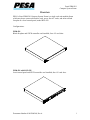
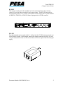
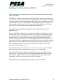
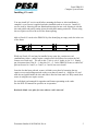
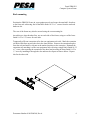
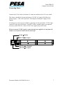
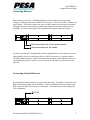
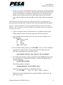
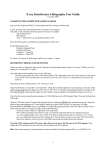
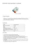
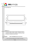
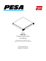
Fortel
FRM-501
Compact System Frame
User Manual
Document Number 81905906560, Rev A
Original FortelDTV Text and Format – December 2004
PESA Switching Systems
103 Quality Circle, Suite 210
Huntsville, AL 35806 USA
Fortel FRM-501
Compact System Frame
Overview
PESA’s Fortel FRM-501 Compact System Frame is a single rack unit modular frame
which may house a network interface card, one to four AV cards, and either a blank
faceplate or a local control panel, model RCP-502.
Configurations:
FRM-501
Blank faceplate and ZFCB controller card installed; four AV card slots.
FRM-501 with RCP-502
Local control panel and ZFCB controller card installed; four AV card slots.
Document Number 81905906560, Rev A
1
Fortel FRM-501
Compact System Frame
RCP-502
This remote control panel when installed as a local control panel may also remotely
control AV cards in other networked Fortel system frames. The RCP-502 may also be
used separately and serve as a remote control panel on the LAN for all AV cards installed
in FRM-501, FRM-504, or FRM-304 frames equipped with a ZFCB controller.
PSU-502
External redundant power supply module. It plugs into the 12V DC connector on the rear
of the FRM-501 frame. If the integral, main power supply should fail, the PSU-502 will
carry the load until the frame can be removed from service for repair of the failed integral
supply.
Document Number 81905906560, Rev A
2
Fortel FRM-501
Compact System Frame
Installation
Unpacking
The FRM-501 carton should contain the following items:
•
•
•
Fortel FRM-501 Compact System Frame with rack mount ears attached
Instructions
Hardware kit with rear rack mount brackets and all mounting screws:
• Short Adapter Bracket (Qty. 2)
• Long Extension Bracket (Qty. 2)
• Clip Nut (2)
• 10-32 x 1” Black screws (Qty. 6)
• 10-32 x ½” Bright Screws (Qty. 6)
Document Number 81905906560, Rev A
3
Fortel FRM-501
Compact System Frame
Installing a Local Control Panel – RCP-502
This procedure requires removal from the rack and placement on a level work surface
before proceeding.
The FRM-501 Compact System Frame ships with attached L-brackets used for mounting
in a 19” EIA rack. These must be removed to install the RCP-502 Compact Control Panel
as a direct replacement for the standard face plate. Remove the two brackets and save for
reuse. Remove the top cover from the frame. Slide the blank face plate assembly out of
the front of the frame about one inch. Disconnect the ribbon cable from the JP4 socket
on the ZFCB controller board, leaving it attached to the LED board.
If you wish to change the factory assigned IP address, follow the procedure in
Appendix A now.
Remove the ZFCB controller card by releasing the card ejectors and sliding the card out
the front of the frame. Locate the two cable sockets J1 and J2 on the mid-plane board,
just below the baseline of the ZFCB card. J1 is at the right hand end below the ZFCB
(nearest the fan). J2 is at the left head end below the ZFCB (farthest from the fan).
Connect the LAN jumper cable to J1. Connect the PWR cable to J2. Route these cables
to the front of the frame, keeping them under the ZFCB card as you re-install it in its card
guides and sockets. Retain the ZFCB in its socket by locking the two card ejectors. If
this is a mobile installation, secure the right hand card ejector with a new tie wrap
through the PCB hole adjacent to P5.
Separate the RCP-502 main assembly from its rear case. The rear case is not used and
may be discarded if this is a permanent conversion to a local control panel.
Connect the PWR and LAN cables from the FRM-501 frame to the RCP-502 control
panel. Be sure to connect both the power and communications cables. Slide the panel
into the frame. Replace the top cover. Re-install the L-brackets, securing the screws
through the L-bracket, the frame sidewall and RCP-502 bracket.
This procedure may be employed before or after AV cards are installed.
Document Number 81905906560, Rev A
4
Fortel FRM-501
Compact System Frame
Installing AV cards
You may install AV service cards before mounting the frame or after installation is
complete, even if power is applied and other installed cards are in-service. Install AV
service cards by removing the rear blank and inserting the new card, aligning it with the
slot card guides and gently seating it into the mid-plane mating connector. Secure using
the two captive screws to the rear of the frame opening.
Add an Fortel AV cards to the FRM-501 by first identifying an empty card slot in the rear
of the frame.
1
2
4
3
While any Fortel AV card may be installed in any open slot, certain two-card
combinations (video + audio) require a simple rule to be followed to activate the full
feature set of each card.. The rule is this: Video in slot N, Audio in slot N+1. Simply
put, this means that if slot N = 1, then slot N+1 = 2. In the FRM-501 frame, a related AV
pair can be used in 1 and 2, or 2 and 3, or 3 and 4, but not in 4 and 1.
Once the slot has been selected, remove its blank cover plate by loosening the two
captive screws and pulling outward on the cover plate to remove it. Align the AV card
with the card guides inside the slot, and slide it into the frame until it is fully seated, then
secure it using the two captive screws.
See individual card manuals for operation and features pertaining to the cards.
See the RCP-502 manual for specifics on its operation.
Retain the blank cover plate for reuse when a card is removed.
Document Number 81905906560, Rev A
5
Fortel FRM-501
Compact System Frame
Rack mounting
Position the FRM-501 frame in your equipment rack and secure the attached L-brackets
to the front rack rails using four of the black finish 10-32 x 1” screws from the enclosed
hardware kit.
The rear of the frame may also be secured using the rear mounting kit.
Attach the two short brackets first, one on each side of the frame, using two of the brass
finish 10-32 x 1/2”screws for each side.
Temporarily affix one extension rail to the rear equipment rack rails. Mark the extension
rail hole which lines up with the slot in the short bracket. Remove the extension bracket
from the rack and attach a clip nut at the marked position on the extension. Reinstall the
extension rail, attaching it to the rear equipment rack rail using a single black finish 10-32
x 1” screw, then securing the extension to the short bracket using the brass finish 10-32 x
½” screw by installing it through the slot and into the clip nut as shown below. Repeat
this for the other side.
Document Number 81905906560, Rev A
6
Fortel FRM-501
Compact System Frame
Connecting Power
Connect the AC line cord to the frame AC connector and then to the AC service outlet.
This frame is intended to be operated using a 110-220V AC supply, 50/60 Hz as its
primary supply. A line cord is provided. The integral switching AC supply is autoranging.
A backup power source may be added by connecting it to the unswitched, 12V DC input
connector on the rear of the frame. Fortel DTV offers a suitable supply as an optional
accessory, model PSU-501. Other 12V DC 10A supplies may also be used.
When an external 12 VDC supply is connected and power applied to it, the frame will
remain on even if the AC main switch is turned off.
Fuse Holder
DC Power Input
1
2
4
3
AC Power Switch
AC Power Input
Document Number 81905906560, Rev A
7
Fortel FRM-501
Compact System Frame
Connecting Ethernet
When used on a network, a 100 Mbps Ethernet switch should be connected using
Category 5 Ethernet patch cables with RJ-45 connectors. There are two RJ-45 connectors
on the frame. The left one (next to the power switch) connects the network to the frame.
The right one (next to the card bay) connects the network to the local control panel (if
installed). If a local control panel is not installed, this connector may not be used.
1
2
4
3
LAN connection for local control panel
LAN connection for all cards
If a local control panel is installed and network communication is not required, you must
either install a crossover cable between the two RJ45 connectors, or, connect both to a
100 Mbps Ethernet switch. When both connections are made to the Ethernet switch, the
control panel may also be used to serve as a remote for all other Fortel products on the
network.
Connecting Genlock Reference
An external black burst reference is required for this frame. It should be connected to the
REF IN connector on the rear of the frame. Connect a blackburst reference signal to the
BNC connector (REF IN) on the rear of the frame. This connection is non-looping and
self- terminating.
REF IN
1
2
Document Number 81905906560, Rev A
4
3
8
Fortel FRM-501
Compact System Frame
Applying Power
Apply power to the frame by depressing the upper half of the rocker switch. When
power is first applied, a red ATTN lamp will light on the front cover while the network
control card is booting. The green LINK lamp will light if the Ethernet connection is
good. The green ACT lamp lights only when a command is received from or sent to the
network.
AC Power Switch
OFF Position
ON Position
Front Panel Status LEDs
System fault or booting
ACT LINK ATTN
Network is connected
ZFCB transmitting/receiving
Document Number 81905906560, Rev A
9
Fortel FRM-501
Compact System Frame
Appendix A
Changing Frame IP Address
The ZFCB Control Board communicates with the various Fortel AV service cards,
interpreting control commands and status information to (and from) the network. Each
FRM-501 Fortel system frame contains one ZFCB control board. The board is located in
the front card bay. This procedure describes the method to be used by the installer to
change the Net Address of the ZFCB. On a dedicated LAN, it is normally not required
for the installer to change the IP address of a frame. When multiple frames are installed
on the same LAN over time, it is possible that an IP address conflict could be created as
new equipment is added. Each ZFCB ordered in one purchase has a different IP address
set at the factory.
Updating the ZFCB requires removing the FRM-501 from service until the update is
completed, which only takes a few minutes. AV service cards will continue to operate,
but remote control access will be suspended until a cold boot restart is performed. Cards
will not be accessible by a control panel until the update is completed.
Performing this update requires a FRM-501 frame with a ZFCB installed, a DB9 serial
crossover cable, your PC equipped with an available serial port, and a HyperTerminal
utility.
IP Address Rules. All Fortel system frames and control panels must be assigned IP
Address values which do not violate the subnet mask restrictions. The normal subnet
mask is 255.255.255.0, which requires that all Fortel products must have identical values
in the first three bytes of the IP Address, with the fourth byte being a unique value
between 0 - 255, such that no two devices on the LAN have the same IP Address.
Example: 192.168.0.86 and 192.167.0.150 would not communicate, but 192.168.0.86
and 192.168.0.150 would communicate correctly.
Each ZFCB card has an IP address, subnet mask, and gateway that can be modified by
the installer using the following procedure.
Document Number 81905906560, Rev A
10
Fortel FRM-501
Compact System Frame
1. Remove the faceplate of the FRM-501 frame by loosening the attached L-brackets
used for mounting in a 19” EIA rack. These must also be removed if an RCP-502
Compact Control Panel is installed as a replacement for the standard face plate.
Remove the two brackets and save for reuse. Remove the top cover from the
frame. Slide the blank face plate assembly out of the front of the frame about one
inch.
The ZFCB card is located in the front bay card and is secured by two latching card
ejectors at the left and right ends. Removal of the ZFCB is not required for this update.
Caution – a factory installed tie-wrap secures the ZFCB right side card lock during
shipment. Do not attempt to remove the ZFCB from the frame without first cutting and
removing the tie wrap!
2. Connect your serial crossover cable from the PC’s available serial port to the
DB9M connector located on the front edge of the ZFCB control board.
3. Open a HyperTerminal window on your PC and set session variables to the
following values:
38400 Bits per second
8
Data bits
N
Parity
1
Stop Bit
None Flow Control
4. In the connection dialog window, press [ENTER] to verify you have established
communication with the ZFCB. If successful, this will be indicated by the
following prompt appearing in the dialog window:
Unrecognized Command. Type ‘help’ for a list of commands.
5. The ZFCB control board is running an application called fortelconv which must
be terminated prior to changing the IP address. Terminate the application by
typing the following:
quit [ENTER] [ENTER]
The following prompt will appear:
Starting application. Press ENTER to abort.
Navigate to the correct directory by typing the following:
cd / [ENTER]
( type: “cd” <space> <slash> <ENTER> )
Display the currently installed network settings (IP Address, subnet mask and
gateway) by typing:
Document Number 81905906560, Rev A
11
Fortel FRM-501
Compact System Frame
cat cfgnet.sh [ENTER]
The HyperTerminal dialog window will display the following (or similar)
prompts:
if config eth0 192.168.0.86
if config eth0 netmask 255.255.255.0
route add default gw 192.168.0.1
(IP address is set to 192.168.0.86)
(subnet mask is set to 255.255.255.0)
(gateway is set to 192.168.0.1)
Start the network configuration tool by typing:
cbconfig [ENTER]
Enter the desired IP address in the format 192.168.0.44 :
192.168.0.99 [ENTER]
(type your new value – i.e., “192.168.0.99”)
Note - If this is a value you do not wish to change, you must re-enter the old value.
Enter the desired Netmask in the format 255.255.255.0 :
255.255.254.0 [ENTER]
(type your new value – i.e.,
“255.255.254.0”)
Note - If this is a value you do not wish to change, you must re-enter the old value.
Enter the desired Gateway in the format 192.168.0.1 :
192.168.0.2 [ENTER]
(type your new value – i.e., “192.168.0.2”)
Note - If this is a value you do not wish to change, you must re-enter the old value.
After entering the new Gateway value, the cbconfig utility will display this
prompt:
Press ENTER to enable new settings, q to quit without using.
Press [ENTER] to accept the new settings or press q [ENTER] to abort without
saving.
If you accepted them in the step above, the cbconfig utility will prompt:
Press ENTER to save new config to flash, q to quit without saving.
Type q [ENTER] to invoke the Save Settings to Flash utility.
Save the settings to flash and make them permanent by typing:
. cfg.sh save [ENTER] (type: <period>, <space>, "cfg.sh save")
Wait a few moments for the following prompts to appear:
Saving Config scripts to flash
Erasing Flash sector d
init-2.05#
Document Number 81905906560, Rev A
12
Fortel FRM-501
Compact System Frame
6. While your PC remains connected, cycle power on the Fortel system frame and
wait patiently for the system to reset and reload all settings. This will take several
minutes and varies depending on how many service cards are installed in the rear
of the frame. While the reload is progressing, a series of status messages will
appear in the HyperTerminal window which can be ignored. The reload is
complete when you see the following prompts in the HyperTerminal dialogue
window:
Starting Heart [DONE]
Pulse: 60 BPM
You may now retrieve the new settings by typing the following:
ifinfo [ENTER]
7. Close the HyperTerminal window and disconnect the serial crossover cable from
the DB9 connector on the ZFCB. Make sure the ZFCB card is still seated
securely in its card socket and that the card locks are fully engaged after removing
the serial cable. Replace the EMI shield cover using the nine Phillips head
countersink screws, oriented so that the LED status array is visible through the
cover when secured. Verify that the frame power supplies are switched on and
replace the snap-on front cover. The RCP-303 Express remote control panels will
recognize the new frame settings automatically.
SERVICE AND ORDERING ASSISTANCE
SERVICE DEPARTMENT
MAIN OFFICE
PESA Swithcing Systems
103 Quality Circle, Suite 210
Huntsville AL 35806 USA
www.pesa.com
Tel: 256.726.9222 (24/7)
Toll Free: 800.323.7372
Fax: 256.726.9268
Email: [email protected]
Tel: 256.726.9200
Fax: 256.726.9271
Document Number 81905906560, Rev A
13