1
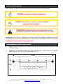
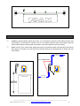
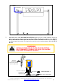
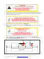
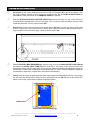
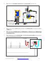
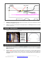
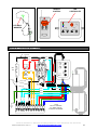
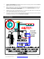
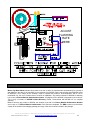
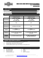
BUBBLE ARCH, FOAM CURTAIN INSTALLATION MANUAL Part # FOAMCURT000XXXX FOAMBUBL000XXXX TABLE OF CONTENT Equipment Utilities Equipment Specifications Bubble Arch Installation Foam Curtain Instructions Page: 1 Page: 1 Page: 2 Page: 10 Equipment Utilities FOAM CURTAIN ARCH FOAMCURT000XXXX BUBBLE ARCH FOAMBUBL000XXXX ELECTRICAL 115 VAC, 1 PH, 15AMPS FLA: 10AMPS (INCLUDING SIGN) 115 VAC, 1 PH, 15AMPS FLA: 10AMPS (INCLUDING SIGN) HYDRAULIC N/A N/A PNEUMATICS 10 SCFM @ 100 PSI (MAX) N/A WATER FRESH: 5 GPM @ 40 PSI (MAX) FRESH: 10 GPM @ 40 PSI (MAX) CHEMICALS 2 OUNCES PER CAR (AVERAGE) @ 120CPH 2-4 OUNCES PER CAR (AVERAGE) @ 120CPH OUTPUTS (CAR WASH CONTROLLER) (1), ONE FOR CONTROL PANEL (2), ONE FOR CONTROL PNL AND ONE FOR DLTN STN Equipment Specifications and Features Convenient 115VAC Single Phase Supply Minimize Installation Cost Oversized Back Lit Sign Customizable to your Request Compact Design: Utilize only 3-0” of Tunnel Space Two Exiting foaming options: Triple Foam and Single Foaming Bubble Arch Suggested Installation Tools and Materials 5 MEASURING TAPE BALL PEN HAMMER WRENCHES ASSY SCREWDRIVERS ASSY HAMMER DRILL WITH 1/2IN WEDGE ANCHORS LEVEL LADDER SAFETY GOGGLES © Motor City Wash Works, Inc. 48285 Frank, Wixom Michigan 48393 U.S.A. Phone: 248.313.0272 ▪ Fax: 248. 313.0271 8MANLFOMARCH0001 REV 1.0 www.motorcitywashworks.com 1 Notes and safety Symbols Where necessary, important points will be highlighted in this manual, using the following symbols: NOTES: PROVIDES FURTHER INFORMATION! STOP! PRECAUTION TO TAKE TO AVOID EQUIPMENT MALFUNCTION OR ERROR! WARNING! DANGEROUS SITUATION WHICH MAY CAUSE EQUIPMENT DAMAGES, PERSONAL INJURIES OR FATALITIES! Always follow all “Notes”, “Warning” and instructions. Not doing so may have serious consequences on the overall performance of the washing equipment and/or the safety of the people working on and with the equipment! Installation Instruction for FOAM ARCHES : 5 Open all boxes and crates and verify that you have all the required components as well as all your installation material. Locate where the arch will be installed and, using the picture below, verify that the area is sufficiently large for your new foam arch working envelope (see Picture 1.0). 144IN 36IN Picture 1.0: Foam Arch Working Envelope © Motor City Wash Works, Inc. 48285 Frank, Wixom Michigan 48393 U.S.A. Phone: 248.313.0272 ▪ Fax: 248. 313.0271 8MANLFOMARCH0001 REV 1.0 www.motorcitywashworks.com 2 144IN 30IN 120IN Picture 2.0: Foam Arch Overall Dimensions 120in 140IN Picture 3.0: Foam Arch Overall Height Assemble the frame (like shown on Picture #4.0 below) in the area where the arch will be installed and stand the frame up. The fasteners are shipped secure to the leg (top of the legs). Picture 4.0: Assembles the Frame © Motor City Wash Works, Inc. 48285 Frank, Wixom Michigan 48393 U.S.A. Phone: 248.313.0272 ▪ Fax: 248. 313.0271 8MANLFOMARCH0001 REV 1.0 www.motorcitywashworks.com 3 Position the frame with the driver side LEG OUTSIDE EDGE 45IN away from the INSIDE EDGE of the CONVEYOR INSIDE GUIDE RAIL. Secure the frame to the floor using ½”X4-1/2” wedge anchor bolts. Level the arch as shown below and shim under the base plate if needed. LEVEL LEVEL LEVEL 45IN Picture 5.0: Level The Arch Secure the head assembly on wood boards and removes the four crossbeam clamp (see Picture #6.0). Lift the head assembly toward the entrance side of the arch and, using the four clamps, secure the head assembly to the 4X4 arch crossbeam (see picture #7.0). Do not tighten the clamps to the beam yet. Centers the head assembly onto the crossbeam, slowly drop the head assembly from the lifting device. This will allow the head to hang from the fasteners insuring that the head will be level when the fasteners are tightened. Then tighten the clamps to the beam. Open the front door and unroll down the vinyl strip. (4) CLAMPS WASH ENTRANCE WOOD BOARDS Picture 6.0: Remove the Clamps Picture 6.1: Raise the Head Assembly © Motor City Wash Works, Inc. 48285 Frank, Wixom Michigan 48393 U.S.A. Phone: 248.313.0272 ▪ Fax: 248. 313.0271 8MANLFOMARCH0001 REV 1.0 www.motorcitywashworks.com 4 Picture 7.0: Secure the Clamps to the Beam BUBBLE ARCH Utilities Installation : Locate the optional dilution station and secure it to a solid wall, at least 40 inches above the floor (see Picture #8.0). This will allow for sufficient room for a 55 gallons chemical drum to be position under the dilution station without interfering with its operation. Secure the optional control box close by. Pull a hose 3/4” from a fresh water supply and connect to the dilution station inlet barb fitting (see Picture #8.1 below). Pull another 3/4” hose from the outlet barb fitting to the head assembly on driver side (see Picture #9.0). TO HEAD ASSY DRIVER SIDE 3/4” RUBBER HOSE DLTN STN CONTROL BOX CHEMICAL DRUM FROM FRESH WATER SUPPLY 40IN Picture 8.0: Secure 40In from Floor Picture 8.1: Pull Hoses © Motor City Wash Works, Inc. 48285 Frank, Wixom Michigan 48393 U.S.A. Phone: 248.313.0272 ▪ Fax: 248. 313.0271 8MANLFOMARCH0001 REV 1.0 www.motorcitywashworks.com 5 FROM DILUTION STATION 3/4” RUBBER HOSE 1/2" HOSE CONNECT HERE Picture 9.0: Secure Hose to the Head Assembly Your Bubble Arch needs TWO FUNCTION OUTPUTS signals from your car wash controller: One for the dilution station and one for the control box (see Picture #10.0). The signal for the dilution station HAS TO BE OF THE SAME VOLTAGE THAN THE DILUTION STATION SOLENOID VALVE. Verify the voltage of the dilution station before wiring. The signal to the control box can be anything between 24 to 240 VOLTS AC or D. WARNING! WRONG VOLTAGE APPLIED TO THE DILUTION STATION WILL PERMANENTLY DAMAGE THE VALVE COIL AND MAY ALSO LEAD TO PERSONAL INJURIES FROM CW CONTROLLER F OA M CURT AIN P OWE R SUPPLY CHECK VALVE VOLTAGE BEFORE CONNECTING! FROM CW CONTROLLER 24-240V AC/DC FROM ELEC PANEL 120VAC-15AMPS TO WASH BAY TO WASH BAY BLOWERS JUNCTION BOX BLOWER JUNCTION BOX LED LIGHTS JUNCTION BOX Picture 10.0: Electrical Runs © Motor City Wash Works, Inc. 48285 Frank, Wixom Michigan 48393 U.S.A. Phone: 248.313.0272 ▪ Fax: 248. 313.0271 8MANLFOMARCH0001 REV 1.0 www.motorcitywashworks.com 6 WARNING! THE MATERIAL REQUIRED FOR CONNECTING THE ARCH IS THE CUSTOMER’S RESPONSIBILITY! ALL WORK HAS TO COMPLY WITH LOCAL AND NATIONAL CODES! Pull an electrical run from the car wash controller to the dilution station and connect the dilution station to a separate function output. This set up will allow the dilution station to run and refill the arch after the car leaves the arch and the blower turned off. YOU MAY CONNECT THE DILUTION STATION ON THE SAME OUTPUT FUNCTION THAN THE CONTROL BOX IF THE WATER PRESSURE FEEDING THE DILUTION IS SUFFICIENT TO KEEP UP WITH THE ARCH WHEN RUNNING Pull a second run from the car wash controller to the CONTROL BOX. Run a line from the 120VAC building sub-panel to the CONTROL BOX and connect on a separate 15AMPS circuit. THE ARCH REQUIRES A SEPARATE 15AMPS, 120VAC, 1PH ELECTRICAL CIRCUIT TO AVOID EQUIPMENT MALFUNCTION DO NOT CONNECT ANY OTHER ELECTRICAL DEVICE ON THE SAME CIRCUIT FEEDING THE ARCH Run two separate lines from the CONTROL BOX to the wash bay: one to the LED JUNCTION BOX and one to the BLOWER JUNCTION BOX (see picture #11.0). CONNE CT BLOWER RUN HERE CONNE CT LED LIGHTS RUN HERE ARCH EXIT END Picture 11.0: Arch Junction Boxes © Motor City Wash Works, Inc. 48285 Frank, Wixom Michigan 48393 U.S.A. Phone: 248.313.0272 ▪ Fax: 248. 313.0271 8MANLFOMARCH0001 REV 1.0 www.motorcitywashworks.com 7 Connect the BLOWER and the LED lights runs to each respective junction boxes using the connection diagrams below. TO BLOWER MOTOR TO LED LIGHTS 9 GRD 10 11 12 4 5 FROM CONTROL BOX USE # 14 A WG WIRES USE #16 AWG WIRES MIN FROM CO NTROL BOX Picture 12.0: LED Junction Box 1 2 3 4 5 6 Picture 12.1: Blower Junction Box 7 8 9 10 11 12 RUN TO ARCH INTO (24VDC) LED JUNCTION BOX FROM CAR WASH 24-240V CONTROLLER AC/DC RUN TO ARCH INTO BLOWER JUNCTION BOX FROM 120VAC 15AMPS SEPARATE CIRCUIT Picture 13.0: Control Box Connection Diagram WARNING! RUN TWO SEPARATE LINES FOR BLOWER AND LED LIGHTS DO NOT RUN THE WIRES IN THE SAME CONDUIT © Motor City Wash Works, Inc. 48285 Frank, Wixom Michigan 48393 U.S.A. Phone: 248.313.0272 ▪ Fax: 248. 313.0271 8MANLFOMARCH0001 REV 1.0 www.motorcitywashworks.com 8 Starting-Up Your BUBBLE ARCH: Disconnect the 3/4” rubber feeding hose at the arch and turn the water ON to the Dilution Station. Drop the Dilution Station chemical suction line into the chemical drum. Set the PUMP DILUTION RATIO to about 300:1 (Follow Instructions on the CHEMICAL PUMP user manual). Turn the DILUTION STATION FUNCTION OUTPUT ON and let the water run until a solid column of chemical fills the chemical suction line up to the pump. Let it run until the solution feeding the arch is visibly mixed with chemicals. Turn the output function OFF. Reconnect the hose to the arch and turn the dilution station ON again until the arch trough is filled with solution. Verify that the float stop the flow of solution when reached float level. Adjust the float height to keep the solution level close to the edge. Leave the dilution station ON. FLOAT Picture 14.0: Head Assembly Float Valve Turn the CONTROL BOX BREAKERS ON, close the cover and turn the ARCH OUTPUT FUNCTION ON and observe the READY LIGHT TURN ON (see Picture #15.0). The blower is now running and the foam generated is flowing over the edge down onto the ground. Observe the bubble generated and change the concentration of the solution by adjusting the chemical pump: For “thicker” foam and bubbles increase the concentration of chemical. For lighter foam, decrease the concentration. Finally, turn both output off and program the ready signal output to turn ON slightly before the car reaches the arch while the dilution station output get to be programmed to turn ON with the car and turned OFF after the car is away, long enough to refill the trough with solution. F OA M CURT AIN P OWE R SUPPLY READY LIGHT Picture 15.0: Control Box Ready Light © Motor City Wash Works, Inc. 48285 Frank, Wixom Michigan 48393 U.S.A. Phone: 248.313.0272 ▪ Fax: 248. 313.0271 8MANLFOMARCH0001 REV 1.0 www.motorcitywashworks.com 9 FOAM CURTAIN ARCH Utilities Installation : Locate the optional HP PUMP DILUTION STATION and secure it to a solid wall, at least 40 inches above the floor (see Picture #16.0). This will allow for sufficient room for a 55 gallons chemical drum to be position under the dilution station without interfering with its operation. Secure the optional control box close by. CHE MICA L DRUM CHE MICA L DRUM CHE MICA L DRUM 40IN Picture 16.0: HP Pump Dilution Station Pull a 1/2” hose from a fresh water supply and connect to dilution station inlet barb fitting (see Picture #17.0 below). Pull a 3/8” O.D. air line tubing from compressed air supply and connect to the air solenoid valve inlet located under the pump wall frame (see Picture #17.0). TO FOAM CURTAIN ARCH 1/2IN O.D. CLEAR TUBING FOA M CU RTAIN P OWE R S UPPLY MO TOR C ITY FOAM CURTAIN FOA M AIR 3/8IN O.D. BLACK TUBING FROM FRESH WATER SUPPLY FROM COMPRESSED AIR SUPPLY Picture 17.0: HP Pump Dilution Hose and Tubing © Motor City Wash Works, Inc. 48285 Frank, Wixom Michigan 48393 U.S.A. Phone: 248.313.0272 ▪ Fax: 248. 313.0271 8MANLFOMARCH0001 REV 1.0 www.motorcitywashworks.com 10 WARNING! IT IS IMPERATIVE TO SUPPLY THE DILUTION STATION SYSTEM WITH “CLEAN DRY COMPRESSED AIR” ANY AMOUNT OF MOISTURE, VAPORIZED OIL OR ANY OTHER IMPURITIES WITHIN THE MAIN AIR SUPPLY MAY AFFECT THE PERFORMANCE OF THE EQUIPMENT AND LEAD TO PREMATURE WEAR OR MAJOR DAMAGE TO THE FOAM CURTAIN ARCH DELIVERY SYSTEM OR ITS COMPONENTS Pull three 1/2” O.D. air line from the pump injector outlets to the foamer generator located onboard of the arch (see pictures 17.0 and 18.0). RED CHEMICAL YELLOW CHEMICAL BLUE CHEMICAL FROM MECH ROOM COMPRESSED AIR Picture 18.0: Arch Tubing View from Top Your FOAM CURTAIN ARCH CONTROL BOX needs SEPARATE POWER SUPPLY from the 120/220VOLT building electrical panel and ONE FUNCTION OUTPUT signals from your car wash controller: The signal to the control box can be anything between 24 to 240 VOLTS AC or DC. WARNING! THE MATERIAL REQUIRED FOR CONNECTING THE ARCH IS THE CUSTOMER’S RESPONSIBILITY! ALL WORK HAS TO COMPLY WITH LOCAL AND NATIONAL CODES! THE ARCH REQUIRES A SEPARATE 15AMPS, 120VAC, 1PH ELECTRICAL CIRCUIT TO AVOID EQUIPMENT MALFUNCTION DO NOT CONNECT ANY OTHER ELECTRICAL DEVICE ON THE SAME CIRCUIT FEEDING THE ARCH © Motor City Wash Works, Inc. 48285 Frank, Wixom Michigan 48393 U.S.A. Phone: 248.313.0272 ▪ Fax: 248. 313.0271 8MANLFOMARCH0001 REV 1.0 www.motorcitywashworks.com 11 Run a line from the CAR WASH CONTROLLER to the CONTROL BOX (see Picture 19.0) F OA M AIR 24-240V AC/DC FROM ELEC PANEL 120VAC-15AMPS TO WASH BAY TO WATER VALVE MOT OR CI T Y F OAM CURTAIN TO AIR VALVE TO MOTOR 120VAC ONLY! F OA M CURT AIN P OWE R SUPPLY LED LIGHTS JUNCTION BOX Picture 19.0: Electrical Runs Run also a line from the 120VAC building sub-panel to the CONTROL BOX and connect on a separate 15AMPS circuit. Run a lines from the CONTROL BOX to the PUMP MOTOR, the AIR VALVE and the WATER VALVE and connect like shown on the picture #19.0. Use a junction box to connect all the three components. USE #14AWG WIRES ONLY! Run a separate lines from the CONTROL BOX to the LED LIGHTS JUNCTION BOX mounted on the exit end of the head assembly (see picture #20.0). CONNE CT LED LIGHTS RUN HERE 9 10 11 12 USE #16 AWG WIRES MIN Picture 20.0: Led Light J Box © Motor City Wash Works, Inc. 48285 Frank, Wixom Michigan 48393 U.S.A. Phone: 248.313.0272 ▪ Fax: 248. 313.0271 8MANLFOMARCH0001 REV 1.0 www.motorcitywashworks.com 12 Connect the wires in the control box following the schematic on picture #21.0 1 2 3 4 5 6 7 8 9 10 11 12 RUN TO ARCH INTO (24VDC) LED JUNCTION BOX FROM CAR WASH 24-240V CONTROLLER AC/DC RUN TO TRIPLE FOAM WATER AND AIR SOLENOID VALVES RUN TO TRIPLE FOAM PUMP MOTOR 120VAC ONLY! FROM 120VAC 15AMPS SEPARATE CIRCUIT Picture 21.0: Electrical Connections Schematic Starting-Up Your BUBBLE ARCH: Disconnect the 1/2” rubber feeding hose at the pump and turn the water ON to “flush” the line. Shut the water OFF and reconnect the hose. Select an injector “tip” according to the CHEMICAL USAGE CHARTS below. A TURQUOISE tip may use less chemical per car than using a PINK. Using a PINK instead may use more chemical but may generates foam with more vivid colors (when using triple foam for example). TIP COLOR (FOR 0.057’’ INJECTOR) TURQUOISE CHEMICAL USAGE (PER COLOR) CARS PER HOUR TIME ON EACH CAR (sec) CHEMICAL USAGE PER CAR 1 COLOR (oz) CHEMICAL USAGE PER CAR 3 COLORS (oz) 1.33 OZ/MINUTE 60 80 100 120 140 160 180 60 45 36 30 25 22 20 1.33 1.00 0.80 0.67 0.57 0.50 0.44 3.99 3.00 2.40 2.01 1.71 1.50 1.32 Picture 22.0: Turquoise Tip Usage Chart © Motor City Wash Works, Inc. 48285 Frank, Wixom Michigan 48393 U.S.A. Phone: 248.313.0272 ▪ Fax: 248. 313.0271 8MANLFOMARCH0001 REV 1.0 www.motorcitywashworks.com 13 TIP COLOR PINK CHEMICAL USAGE (PER COLOR) CARS PER HOUR TIME ON EACH CAR (sec) CHEMICAL USAGE PER CAR 1 COLOR (oz) CHEMICAL USAGE PER CAR 3 COLORS (oz) 2.5 OZ MINUTE 60 80 100 120 140 160 180 60 45 36 30 25 22 20 2.50 1.88 1.50 1.25 1.07 0.94 0.83 7.50 5.64 4.50 3.75 3.21 2.82 2.49 Picture 23.0: Pink Tip Usage Chart Turn the CONTROL BOX BREAKERS ON, close the cover and turn the PUMP DILUTION STATION FUNCTION OUTPUT ON and observe the READY LIGHT TURN ON (see Picture #15.0). The pump is now running. Set the pressure on the gauge to about 100PSI (see picture #24.0). Let the water run until a solid column of chemical fills all the chemical suction line up to the injectors. Let it run until the solution feeding the arch is visibly mixed with chemicals. TURNING THE SCREW CW INCREASES THE PUMP PRESSURE TURNING THE SCREW CCW DECREASE THE PUMP PRESSURE Picture 24.0: Dilution Station Pump Increase the air regulator gauge to a value between 20-40PSI and go to the arch and notice foamer generator starting to foam. Balance the foam generation between the three foam generators by opening or closing the air supply ball valves mounted on each generator. © Motor City Wash Works, Inc. 48285 Frank, Wixom Michigan 48393 U.S.A. Phone: 248.313.0272 ▪ Fax: 248. 313.0271 8MANLFOMARCH0001 REV 1.0 www.motorcitywashworks.com 14 FOAMER GENERATOR BALL VALVE Picture 25.0: Ball Valve Observe the foam generated. You may change the concentration of the solution by adjusting the pressure of the pump or changing the injector tip. Finally, turn the output off and program the ready signal output to turn ON slightly before the car reaches the arch. Test with a car. Color Skinz™ Wrap Installation Locate the boxes containing the COLOR SKINZ™ wraps and install on each legs and frame cross beams. SELECT THE PROPER COLOR SKINZ™ COVER. SNAP ONE SIDE OF THE LIPS, SLIDE THE COVER AROUND THE LEG AND FINALLY SNAP THE SECOND LIP PASSED THE EXTRUSION EDGE (see Picture #9-B) Picture 26.0 Color Skinz™ Picture 26.1 Picture 26.2 Color Skinz™ LED LIGHT REMOTE CONTROL: Your foaming arch comes with a set of LED WALL WASHERS mounted in the head cover (see picture #27.0). The wall washer LED light patterns are controlled by a LED controller located in the CONTROL BOX (see Picture 27.1). Using the “MODE” button (on either the LED controller in the control box or using the hand held remote unit) you may change the pattern and the resulting color in which the three colors (RED, GREEN and BLUE) will be lighting on the sign as well as the vinyl strip. Use the BRIGHTNESS and the SPEED button as needed. © Motor City Wash Works, Inc. 48285 Frank, Wixom Michigan 48393 U.S.A. Phone: 248.313.0272 ▪ Fax: 248. 313.0271 8MANLFOMARCH0001 REV 1.0 www.motorcitywashworks.com 15 LED CONTROLLER REMOTE CONTROL ON/OFF R MODE LED WALL WASHERS G B- B+ S- S+ on/off mode B Brightness Picture 27.0 LED Wall Washer speed Picture 27.1 LED Controller Control Box Electrical Schematic: #14AWG BLK #18AWG RED 120V-CB1 120V-CB1 120V-CB1 24VDC mo de 120V-PR1 PWR RELAY B rig htn ess M1 PR-A2 0VDC PR1 R 14 A2 24VDC-M1 A1 B 11 CB1 15A G o n /off s peed 12 PR-A1 120VAC #18AWG YLW BLK RED #14AWG BLK 0VDC 0VDC 0VDC #18AWG WHT 24VDC 120V-CB1 NEUTRAL BLK WHT BLK G RN GRO UND WHT NEUTRAL WHT OR BLK RED O R BRW 120VAC PR-A2 PR-A1 120V-M1 NEUTRAL NEUTRAL G RN BLUE NOTE: INSTALL FERRULES ALL WIRES UNLESS SPECIFIED OTHERWISE 1 2 3 4 5 6 7 8 9 10 11 12 Picture 28.0: Control Box Electrical Schematic © Motor City Wash Works, Inc. 48285 Frank, Wixom Michigan 48393 U.S.A. Phone: 248.313.0272 ▪ Fax: 248. 313.0271 8MANLFOMARCH0001 REV 1.0 www.motorcitywashworks.com 16 Optional Arch Light Kit: Part # ARCHLIGHTKITXXXX Electrical Specifications: Light Kit………………………………..………………..24VDC Flasher Unit…………………………….Supply: 120VAC, 2A Control: ………………………………………24-250V AC/DC Suggested Installation Tools and Materials 5 3/16” Socket Head (Allen) Wrench 1/8” Socket Head (Allen) Wrench 6’ Step Ladder Wire Stripper and Wire Ties 2 Conductors #14 AWG Low Voltage Cable Water Proof Wire Nuts Installation Procedures: 5 Upon receiving your MCWW Light Kit, open the box and verify that you have all the required components and there is no damage to the equipment. Verify also that you have all your installation material. Picture 29.0: LED String Picture 29.1: Other LED String Picture 29.2: Flasher Unit Locate the aluminum channels and secure to the arch legs (see picture 27.0) OPTIONAL ROUND SIGN ALUM CHANNELS CONNECT INTO LEG Picture 30.0 LED Aluminum Channels Picture 30.1: LED String © Motor City Wash Works, Inc. 48285 Frank, Wixom Michigan 48393 U.S.A. Phone: 248.313.0272 ▪ Fax: 248. 313.0271 8MANLFOMARCH0001 REV 1.0 www.motorcitywashworks.com 17 Install the LIGHT STRING into the channels. Pull the cord thru the opening. Pull the cord thru the UTILITY HOLE located on the outside face of the leg. Pull a 2 Conductors PVC Jacket #14 AWG Low Voltage Cable from the mechanical room to the arch, pull the cable through the leg and connect to the LED string cord using WATER RESISTANT wire nuts (see Picture 27.1). Finally install the leg Color Skinz™. Install the power supply in the Mechanical Room or in a dry area of the wash, close to a 120 VAC power outlet. Install the flasher assembly close to the power supply. Connect the cord end of the power supply to the flasher unit (see Picture 26.2) and to the 2c/14 cable of the LED light kit following one of the next ELECTRICAL DIAGRAMS. Electrical Diagrams C NC NO C NC NO ~ 1 V ~ 2 4 5 67 3 8 2 9 1 0.1 10 120VAC or ADJUST FLASHING RATE HERE 24VAC/DC Picture 28.0: Connection Diagram of Flasher Unit with Light Always OFF © Motor City Wash Works, Inc. 48285 Frank, Wixom Michigan 48393 U.S.A. Phone: 248.313.0272 ▪ Fax: 248. 313.0271 8MANLFOMARCH0001 REV 1.0 www.motorcitywashworks.com 18 C NC NO C NC NO ~ 1 V ~ 2 456 7 3 8 2 9 1 0.1 10 120VAC or ADJUST FLASHING RATE HERE 24VAC/DC Picture 29.0: Connection Diagram of Flasher Unit with Light Always ON Warranty and Return Procedure: Motor City Wash Works warrant this product to be free of defect in material and/or workmanship for a period of one year from the date of the purchase by the customer from MCWW. During the warranty period MCWW will at its discretion, at no charge to the customer, repair or replace this product if found defectives, with a new or refurbished unit, but not to include costs of removal or installation. Any product returned to MCWW for warranty has to have a Return Material Authorization Number. All shipping cost to MCWW is assumed by the customer. This is only a summary of MCWW Limited Warranty. Please, communicate with MCWW for our complete warranty. Prior to returning any product to MCWW, the customer must call in for Return Material Authorization Number and a copy of our Return Material Authorization Form filled and completed. The RMA number must be written clearly on the outside of the shipping package and copy of the form must be included in the package. © Motor City Wash Works, Inc. 48285 Frank, Wixom Michigan 48393 U.S.A. Phone: 248.313.0272 ▪ Fax: 248. 313.0271 8MANLFOMARCH0001 REV 1.0 www.motorcitywashworks.com 19