1
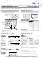
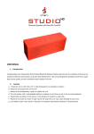
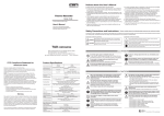
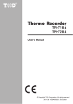
Request a price at: http://dataloggerinc.com/contact/price-request.php
1-800-956-4437
T&D CORPORATION
Voltage Recorder
All Types of Sensors can be Connected for
the Recording of Various Data:
Giving you a Low Cost yet
High Performance Versatile Data Logger.
Voltage Data Logger
VR-71
Display is a composite.
** The images in this document have been optimized for rapid downloading
Request a price at: http://dataloggerinc.com/contact/price-request.php
1-800-956-4437
Request a price at: http://dataloggerinc.com/contact/price-request.php
1-800-956-4437
Voltage Recorder
The VR-71 data logger measures and records voltage signals within a
measurement range of DC (±) 15V. It can record signals of 1-5V / 4-20mA as well
as output signals from a variety of sensors. The most impressive feature is the
software function that allows you to create your own dot matrix patterns for unit
display and then change the recorded voltage signal into the desired unit and
display accordingly to match your measurings.
Measure/Record
Download and Analyze
Connect to a Computer
Connect
Connect
Features
Measure and Record with 2 Channels on 1 Unit
9 Months of Continuous Use on 2 AAA Batteries*
It is possible to measure and record on two channels with 1 unit. These two
channels make it possible to obtain reliable readings when measuring two
related phenomena.
By pressing the DISPLAY button, you can choose to set the LCD display to
show both channels' readings alternatively, show one channel as a fixed display
or show neither channel.
Using our specially designed low energy consumption circuit this unit can run
on two AAA alkaline batteries for up to one year of continued use. No need to
worry about where you place it as the battery will allow you to measure and
record over long periods of time whether the unit is in transit or in a distant
place.
Choose the Display Unit
Of course you can display the voltage reading as is, or by using the software to
select the desired scale, convert and display the readings in the unit of your
choice.
Scale Conversion
You can specify to convert the scale by specifying values at 2 voltage points or by using the
conversion equation of y=Ax+B.
(y stands for the value after conversion and x is the voltage input directly from the sensor.)
EX: At 2 specified points: convert input voltage of 0v to 100 and input of 5v to 5000.
EX: Using the equation y=Ax+B: y=10x+15.
Unit Display
It is possible using the software to create and edit dot matrix patterns to be used in the LCD as the
unit of measurement.
Example of
Created Dot Matrix Pattern
*Note:Battery life will depend on the recording environment, recording interval, communication frequency, and
ambient temperature. The above battery life test was carried out using brand new batteries and in no way
do we guarantee a battery's life.
Reliable Backup Function
We have eliminated the worry of losing data due to power loss or the switch
being accidentally turned off.
When Battery Power becomes Low
When battery power becomes low a battery life warning will appear on the unit's display indicating
that the battery should be changed. If within a short time the battery is changed, measurement and
recording will not be interrupted and there will be no data loss. If the battery is not changed the unit
will automatically go into SLEEP mode whereby measurement and recording will stop but, due to
our BACK UP FUNCTION, data will not be lost and will remain saved for up to one year.
Battery LifeWarning Indicator
Sleep Mode Indicator
Example of
Created Unit Display
When the Switch is turned OFF
If while recording, the power switch is accidentally turned OFF, data will not be lost but will be
saved for up to one year from the time it was switched OFF.
Note:Even if the unit is in sleep mode it needs battery power. Hence, a total loss of battery power or removal of
the battery will result in the loss of data.
Auto-Range Function /±Input
Easy to Read Multi-Functional Display
You can manually set the range or can set to have the auto-range function
automatically select the best range from the 4 input ranges
±1V, ±2V, ±6V, ±15V.
The easy to read LCD displays
the current readings, recording
status, battery life warning,
and unit of measurement.
Note: If the recording interval is 0.5 seconds or less the auto-range function cannot be used.
Select from 20 Recording Intervals / Shortest at 0.02 seconds
Recording interval can be selected from 20 choices (0.02sec to 60min)
There are also two Recording Modes to choose from: One-time or Endless.
Data Capacity: 8000 Readings x 2 Channels
Each channel can record up to 8000 readings. At a recording interval of 60 min,
(the longest possible recording interval) that gives you one year of continuous
recording capability.
(1) The channel number of the measurement being displayed will appear.
(2) The recording status will appear.
ON:Recording in progress. BLINKING:Waiting for programmed start.
(3) After every 2000 readings the scale will be marked from left to right.
(4) ONETIME:When the number of recorded readings reaches 8000, "FULL"will appear in the unit's
LCD display and recording will automatically stop.
ENDLESS:When the number of recorded readings reaches 8000, the oldest data reading will be
overwritten and recording will continue.
(5) When the battery power becomes low, this will appear in the LCD display. If the battery power
becomes even lower, SLP will appear and normal operations will stop. If the
signal appears,
please change the battery as soon as possible.
(6) The unit of measurement for the display will appear.
(7) Current measurements or operational messages such as FULL or SLP will appear.
Request a price at: http://dataloggerinc.com/contact/price-request.php
1-800-956-4437
Request a price at: http://dataloggerinc.com/contact/price-request.php
1-800-956-4437
VR-71
Software included with VR-71
Voltage Recorder for Windows
Our easy-to-use software included with this product offers a variety of useful functions at your fingertips including: the control of all aspects of data
downloading, control of recording settings, graph display, printing, and file output.
Up to 8 Channels of Data can be Processed at One Time
By simply downloading the data from the main unit a colorful graph representing that data will be
automatically created. Up to 8 channels (4 units of data) can be represented in one graph.
The data scale and unit to be used in the display can be set with the scale settings.
Programmed Recording Start Function /
Scale and Unit Conversion Function
By setting a date and time in the main unit you can easily program to start recording on that date at
the set time. In the Scale Settings you can set the unit of measurement and the values for the scale
and these settings will be reflected in the LCD on the logger and in Graphs. It is also possible to edit
and create the unit of measurement for display in the logger LCD.
Recording Start Settings
Multi-scale Graph
By using the mouse to drag and draw a box
you can easily zoom in on desired data.
You can also use the menu or the keyboard
to zoom in and out on data.
Vertical Axis of
Each Channel
Scale Settings
Hide / View
Channels
Edit Unit for LCD
Graph / Table Printing Function
You can print out in color or
monochrome the graphs just as they
appear on your screen. You can also
print out in table form all of the data
in order of date and time.
The Vertical Axis
Display ON/OFF
Color Graph Printing
Data List Printing
Vertical Axis
Value
Cursor values and
calculated difference
High / Low /Average
A Cursor Bar
B Cursor Bar
■ By moving the cursors on to a specific date and time you can easily view recorded data as well as
the calculated differences between date A and B.
■ By selecting a calculation range you can have displayed the High, Low and Average readings for
that chosen period.
Optional Accessories
VR-7101
Creating Text Files
You can create Text Files (CSV format, etc...) to allow you the option of processing and managing
your data using Excel, Lotus or any other popular spreadsheet software.
Optional Products
VR-00P1
36in [900mm]
4in [100mm]
Input Cable
Expansion Unit
Cable Length: 40 in (1.0m)
(3)
(4)
(1)
VR-7102
4in [100mm]
Sensor
Sensor
AMP
Sensor AMP
Battery
Sensor
36in [900mm]
Input Cable
Sensor
Cable Length: 40 in (1.0m)
(3)
(2)
VR-7103
4in [100mm]
Sensor
36in [900mm]
4-20mA Probe
Maximum Current Input: MAX 40 mA
Internal Resistance: 100 Ohm
Output: 2V at 20mA / 0.4V at 4 mA
Conversion Accuracy: 0.5%
Cable Length: 40 in (1.0m)
(4)
Sensor
MAX40ma
(3)
(2)
(4)
Materials: (1) Clip (2)M3.5 Crimp Terminal (3)Vinyl Coated Electrical Wire (4)Stereo Mini Jack
TR-1C30
120in [3,000mm]
<Example of Preheat Connection>
<Example of Simultaneous Recording Connection>
The expansion unit greatly increases the application possibilities.
It not only allows you to transmit a preheat signal that is synchronized with the
VR-71 recording timing to turn sensors or other devices ON and OFF, but also
allows you to simultaneously record with up to 4 VR-71 units.
Sensor Extension Cable
Cable length: 120 in (3m)
Splash Resistant
(1)
Materials: (1) Vinyl Coated Electrical Wire
30.5
Wall Attachment
Screws x 2
Double-sided Tape x 1
93
Note: When using to simultaneously record with 4 units, it is necessary to purchase separately 2 VR-1C10
57
TR-00K2
Preheat Output Terminal Contact Capacity: DC30V 100mA ON Resistance: MAX 15Ω
Power Source: 1 AA Alkaline Battery (LR6)
Weight: about 230g (including 1 AA Alkaline Battery)
Items Included: Connection Cables x 2 [VR-1C01 (15cm) x1 and VR-1C10 (1m) x 1]
Wall Attachment Unit (TR-00K2) x 1, AA Alkaline Battery (LR6) x1
connection cables.
Materials: ABS Resin
Request a price at: http://dataloggerinc.com/contact/price-request.php
1-800-956-4437
Request a price at: http://dataloggerinc.com/contact/price-request.php
1-800-956-4437
■ Specifications for VR-71
■ Software Specifications [Voltage Recorder for Windows]
Measurement Item
Voltage
Compatible Devices
VR-71
Number of Channels
2 (common ground)
Number of Channels
8 channels simultaneous display and processing possible to process a
Measurement Range
Range: ±1, 2, 6, 15 V
Measurement Accuracy
± 0.5% ± 5 dgt. (10°C - 30°C)
Display Resolution
Min 1mV
Main Unit Setting (sChannel Name Recording Interval ▪ Recording Method ▪
Recording Interval
20 selections: 0.02 sec - 60 min.
Upper and Lower Limits ▪ Downloading of Recorded Data ▪
Recording Capacity
8000 readings x 2 channels
Expansion Unit Settings ▪ Create display unit and transmit to logger (dot matrix pattern)
Recording Mode
Endless / One-time
Voltage input conversion equation (2-point or y=Ax+B) setup and transmission to logger.
LCD Display Items
Measurement Reading / Recording Status / Time / Memory Capacity
Power Source
Battery Life Warning / Unit of Measurement / 2 AAA Alkaline Batteries (LR03)
Battery Life
About 5-9 months *
Vertically Scroll Graph for Each Channel ▪ Channel Graph Color ▪ Background Color
Interface
Serial communication (RS-232C)
Customize Graph Scale Lines ▪ Turn ON and OFF Channel Display
Dimensions
H 55mm x W 88mm x D 24mm
Move Vertical Scale to Desired Position in Graph (View / Hide Scale For Each Channel)
Weight
About 93g (Including 2 batteries)
Temperature and Humidity
Temp: 0 - 50°C
Durability of the Unit
Humidity: 90% RH or less (non-condensing)
Highest, Lowest and Average Readings ▪ Unit of Measurement.
Waterproof
None
AB Cursor Dates / Times and Data Readings
Attached Sensor / Cable
2 Input Cables (VR-7101)
Included in Kit
Software Set / Serial Communication Cable x 1 / AAA Alkaline Batteries x 2
File Output
T&D Common Data File ▪ Text File (CSV, etc.) (Selected Range or File for Entire Period)
Auto Range / Fixed Range
mixture of up to 4 VR-71 units
Communication Functions
Recording Start (Programmed Start / Immediate Start) ▪ Recording Stop
Auto detect of Serial COM Port.
Graph Display
Graphs for each Channel (Zoom in / out and scroll with mouse or keyboard)
Display Current Data in Trend Graph (no saving to file)
Data Display
Channel Name ▪ Recording Interval ▪ Number of Readings
Calculated Difference between Cursor A and B
User's Manual and Warranty x 1
Printing
Graphs / Tables
Other
It is possible to measure electrical current.
Other
Data List Display ▪ Change Scales ▪ Calculation Range Settings
Compatible OS
Windows 98SE / Me / 2000 / XP
Set Display Range for Vertical Axis
Edit Recording Conditions / Delete Data by Channel / Re-order Data by Channel
* Note: At recording interval of 1 sec: about 5 months / at rec. interval of more than 2 seconds: 9 months /
at a recording interval of 0.02 seconds: about 13 days.
FCC Compliance Statement for American Users
Compatible OS
Microsoft Windows 98SE / Me English
PC/CPU
IBM Compatible with higher than Pentium 90MHz
Microsoft Windows 2000 / XP English
Serial Port (RS232-C D-sub 9pin)
This device complies with Part 15 of the FCC Rules.
Operation is subject to following two conditions: (1) this device may not cause harmful interference. and (2) this
device must accept any interference received, including interference that may cause undesired operation.
NOTE: This equipment has been tested and found to comply with the limits for a Class A Digital Device, pursuant to
Part 15 of the FCC Rules. These limits are designed to provide reasonable protection against harmful interference in
a residential installation. This equipment generates, uses and can radiate radio frequency energy and, if not installed
and used in accordance with the instructions, may cause harmful interference to radio communications.
However, there is no guarantee that interference will not occur in a particular installation. If this equipment does
cause harmful interference to radio or television reception, which can be determined by turning the equipment off and
on, the user is encouraged to try to correct the interference by one or more of the following measures:
-- Reorient or relocate the receiving antenna.
-- Increase the separation between the equipment and receiver.
-- Connect the equipment into an outlet on a circuit different from that to which the receiver is connected.
-- Consult the dealer or an experienced radio/TV technician for help.
Memory
More than 16MB
Hard Disk
More than 2 MB of free space (Data will need more space)
Monitor
Recommend VGA / SVGA (800x600) or higher / more than 256 colors
► About problems downloading data with Voltage Recorder for
Windows
On computers where the Hyper-Threading function is activated, problems have been found to occur when
downloading data with a USB-Serial Cable conversion adaptor. There are two solutions to this problem. The first is
to turn off the Hyper-Threading function (usually done in the BIOS settings). The second possible solution is to
download data on a computer that has a serial port.
Contact your local authorized T&D sales representative about USB-Serial conversion adaptors.
Warning:
This equipment has been verified to comply with the limits for a Class A personal digital device, pursuant
to Subpart B of Part 15 of FCC Rules. Only peripherals (computer input/output devices, terminals, printers,
etc.) certified or verified to comply with the Class A or B limits may be attached to this equipment.
Operation with non-certified or non-verified personal computer and/or peripherals is likely to result in
interference to radio and TV reception. The connection of a non-shielded equipment interface cable to this
equipment will invalidate the FCC Certification of this device and may cause interference levels which
exceed the limits established by the FCC for this equipment.
You are cautioned that changes or modifications not expressly approved by party responsible for
compliance could void your authority to operate the equipment.
■ Standard Kit for VR-71
Manual (Warranty)
Battery
Voltage Data Logger
VR-71
AAA Alkaline Batteries x2 (LR03)
Input Cable x 2
Serial Communication Cable
RS-232C (D-sub 9Pin)
(VR-7101)
Software (CD)
Voltage Recorder
for Windows
■ System Setup
Sensors
Data Logger (VR-71)
Software
Input Cable
Install
Computer
Output
Voltage
signal
Connect
Connect
Communication Cable
File
Connect
Insert
AAA Batteries
Web Site T&D Online
Product information, FAQ and software update downloads.
http://www.tandd.com/
T&D Corporation
5652-169 Sasaga Matsumoto City.
Nagano 399-0033 Japan
Facsimile(+81)263-26-4281
E-mail: [email protected]
Connect
D-sub 9Pin
Printer
D-sub 9Pin
(RS-232C)
Caution regarding safety
To ensure safe operation, carefully read instructions before using this unit.
TandD US, LLC.
Phone: (518) 669-9227
Fax: (518) 583-0917
E-mail: [email protected]
Request a price at: http://dataloggerinc.com/contact/price-request.php
1-800-956-4437