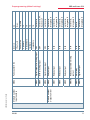
Download technical parameters

Transcript
Quick guide
Technical parameters
Load management system
EDEKZA0024-2614-1_DE-EN
multimax
System I English
4D6
Your partner for
network analysis
Table of contents
1
Introduction................................................................................................................ 3
1.1 Manual.......................................................................................................................... 3
1.2 Intended use............................................................................................................... 3
1.3
Safety notes................................................................................................................. 4
1.4
Product liability.......................................................................................................... 5
1.5Disposal........................................................................................................................ 5
2Installation................................................................................................................... 6
2.1 Device memory, battery-buffered..................................................................... 6
2.1.1 Inserting or replacing the backup battery....................................................... 6
2.2 Device installation.................................................................................................... 6
3
Connection diagram................................................................................................ 8
4
4.1
Control and display panel...................................................................................... 9
Description of buttons and displays,
default settings, setting ranges............................................................................ 9
5
5.1
5.2
5.2.1 5.2.2 5.2.3 5.2.4
5.2.5
5.2.6
5.2.7
5.2.8
5.2.9
Technical data multimax 4D6.............................................................................12
General technical data for additional modules............................................12
Technical data for multimax 4D6 basic module...........................................13
Operating and display elements ......................................................................13
Device memory........................................................................................................13
Power supply............................................................................................................14
Hardware inputs.....................................................................................................14
Electrical connection.............................................................................................14
Hardware outputs...................................................................................................15
Mechanical data and dimensioned drawing of the basic module........15
Environmental conditions / electrical safety.................................................16
Mechanical data for multimax 4F96-DS display...........................................16
© KBR GmbH
All technical data is
subject to change
2
Introduction
1
KBR multimax 4D6
Introduction
Thank you for choosing this KBR quality product. To familiarize yourself with device operation and configuration, we recommend you read this manual carefully.
This will enable you to make use of the entire range of functions that this highquality product offers.
The individual chapters serve to explain the technical details of the device and
show how to properly install and start up the device to prevent damage.
1.1 Manual
This manual is included in the scope of delivery of the device and must be accessible to the user at all times (e.g. in the switchgear cabinet). Even if the device is
resold to third parties, the manual remains an inherent part of the device.
Note
The more comprehensive version of the manual is available online from the
service center at www.kbr.de.
Although the utmost of care has been taken in putting together this user manual, errors may still occur. We would be very grateful if you could notify us of any
errors or unclear descriptions you may notice. The form included in the appendix
to this manual can be used to send us your correction or improvement suggestions.
1.2 Intended use
This device helps you to optimize energy consumption and avoid expensive load
peaks.
It assists you in monitoring the energy consumption of your consumers, enables
you to make optimum use of your tariff and lower your energy costs permanently.
EDEKZA0024-2614-1_DE-EN
This device does not, however, render careful system planning indispensable.
Moreover, it is essential that you take time to configure the device in line with
your system parameters on start-up and carry out proper consumer shutdown
planning.
V4.00
3
KBR multimax 4D6
Introduction
Disclaimer
The contents of this user manual have been carefully reviewed with regard to the
hardware and software described.
Nonetheless, deviations cannot be ruled out, and the manufacturer cannot guarantee 100% conformity. The specifications given in these operating instructions
are reviewed on a regular basis; any corrections required will be included in the
next revision.
1.3
Safety notes
In order to prevent operating errors, device operation is kept as simple as possible. This will enable you to start your device up quickly.
In your own interest, however, the following safety notes should be read carefully. The applicable DIN / VDE regulations must be observed for installation!
Power supply connection, setup and operation of the device must be performed
by qualified personnel only. Qualified personnel as defined in the safety notes
in this user manual are those authorized to set up, ground and mark devices,
systems and circuits in accordance with applicable standards and regulations.
To prevent fire and electric shocks, the device must not be exposed to rain or
humidity!
Before connecting the device to the power supply, check whether the local power supply conditions comply with the specifications on the device nameplate.
Caution
A faulty connection can lead to the destruction of the device!
In order to ensure proper and safe product operation, it must be transported,
stored, installed and assembled in accordance with the specifications, as well as
carefully operated and maintained.
4
V4.00
EDEKZA0024-2614-1_DE-EN
For device connection, the data given in the connection chart must be complied
with (see “Connection chart”) and there must be no voltage in the connection
lines. When wiring, always ensure that all wiring material used is neither damaged nor defective and that the polarity is correct!
Introduction
KBR multimax 4D6
A visibly damaged device must generally be considered unfit for use and
disconnected from the power supply!
Error detection, repair and maintenance work may only be carried out in our
facilities or after contacting our service team. Opening the device unauthorized
shall render your warranty null and void. Correct operation can no longer be
guaranteed!
Opening the device may expose live parts. Capacitors in the device may still be
under load, even if the device has been disconnected from all voltage sources.
Open devices must not be operated!
Systems that are at risk from lightning strikes must feature lightning protection
for all input and output lines!
1.4
Product liability
You have purchased a high-quality product. Only components of the highest
quality and maximum reliability are used.
Each device is subject to long-term testing before it is delivered.
For details on product liability, please refer to our general terms and conditions
for electronic equipment, which you can find at www.kbr.de.
Warranty device properties apply only if the device has been operated in
accordance with its intended use!
1.5Disposal
Defective, outdated or disused devices must be properly disposed of.
EDEKZA0024-2614-1_DE-EN
If required, we are happy to dispose of the devices for you.
V4.00
5
Installation
KBR multimax 4D6
2Installation
2.1 Device memory, battery-buffered
The device is equipped with an internal data memory which is battery buffered
to preserve long-term data. To prevent it from being discharged, this backup battery (e.g. Varta CR 2032) is not built in when the device is delivered, but included
separately in the delivery. Before the initial start-up of the device, please insert
the backup battery first (as described in the following), as otherwise any stored
data would be lost in the event of power failure.
2.1.1 Inserting or replacing the backup battery
1. Disconnect the device from the supply voltage.
2. Lift the upper housing cover using a suitable tool (e.g. a small screwdriver).
3. When replacing a battery, remove the empty battery from the clamping bracket using the tool.
4. Push the new battery into the clamping bracket and make sure that it is inserted correctly and has the right polarity.
5. Replace the upper housing cover and click it back into place.
6. Reconnect the device to the supply voltage.
Caution
When the battery is empty or has been removed, there is no supply voltage. In
this case, not only the storage data is lost, but the time settings have to be reset
as well!
2.2 Device installation
The applicable DIN / VDE regulations must be observed for installation!
The device must be connected in accordance with the connection diagram.
For energy and synchronous pulse input, the correct polarity must be observed
(contact your energy supplier).
Systems that are at risk from lightning strikes must feature lightning protection
for the control voltage, bus line and pulse lines (e.g. energy supplier pulse lines
from the transformer station to the location of the energy control system).
6
V4.00
EDEKZA0024-2614-1_DE-EN
Before the device is connected to the power supply, check whether the local
power supply conditions comply with the specifications on the nameplate.
A faulty connection may destroy the system!
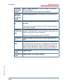
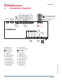
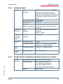
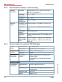
Installation
KBR multimax 4D6
Terminals
1 (L) / 2 (N)
and PE
Power supply connection. Auxiliary voltage is required for
device operation.
For technical data, please refer to the nameplate.
Terminals
90 (earth),
91 (A) and
92 (B)
Interface connection for communication at the energy bus
Terminal 40
(C)
Supply voltage connection to the relay output terminals
41 to 45
The relays for the control outputs share the same connection
to the supply voltage.
Non-floating relay contacts These contacts serve as control
Terminals
41 (k1) to 45 outputs. In the currentless state of the device, the contacts are
open for stages that are not hooked up.
(k5)
Maximum switching capacity of 2A at 250V AC.
Terminal 30
(C)
Supply voltage connection to the relay output terminal 31
(k6)
Terminal 31
(k6)
Floating relay contact. This contact serves as a message or
alarm output. During operation, an audible or visual message
may be activated or a consumer switched off. The contact is
open as long as the device is dead as well as when there is an
active message. Maximum switching capacity 2A at 250V AC.
Terminals 80 Digital output
and 81
EDEKZA0024-2614-1_DE-EN
Terminals 50 Digital inputs, e.g. for pulse counter
to 59
V4.00
7
Installation
KBR multimax 4D6
3
Connection diagram
E1
E2
E3
E4
E5
Dzu weiteren Busteilnehmern
bzw. Leitungsabschluss
Display Modul/
Module
OUT
80 81 50 51 52 53 54 55 56 57 58 59
92 91 90
B A
Output
Ausgang
T
OUT
to other bus devices and
line termination
Inputs
Eingänge
multimax
Netz
Power
40 41 42 43 44 45
c
k1 k2 k3 k4 k5
Relais
Relay
8
c
1
2
PE
k6
AlarmRelay
F1
Terminal assignment
in acc. with factory settings
= Digital output
E1 = Counter input 1
E2 = Counter input 2
E3 = Target value
switchover input
E4 = Tariff change input
E5 = Measuring periods
synchronous pulse input
40 = Control voltage input
41 = Relay output line 1
42 = Relay output line 2
43 = Relay output line 3
44 = Relay output line 4
45 = Relay output
prewarning contact
EDEKZA0024-2614-1_DE-EN
Klemmenbelegung
lt. Werkseinstellung
= Digitalausgang
E1 = Zählereingang 1
E2 = Zählereingang 2
E3 = Sollwertumschalteingang
E4 = Tarif-Umschalteingang
E5 = MessperiodenSynchroneingang
40 = Schaltspannung
41 = Relaisausgang Linie 1
42 = Relaisausgang Linie 2
43 = Relaisausgang Linie 3
44 = Relaisausgang Linie 4
45 = Relaisausgang
Vorwarnkontakt
30 31
V4.00
Control and display panel
4
KBR multimax 4D6
Control and display panel
multimax
P actual
0
Ptarg
Pacc
kW
Trem
12:30 PM 12:40:23 PM 12:45 PM
Pact
Ptrend
Pcorr
1 Display
navigation
panel
2 Data display
®
3 Hot key area
menu
4.1Description of buttons and displays,
default settings, setting ranges
1 Display navigation panel
The navigation panel shows the main menu selected, considerably
simplifying device operation.
The operator can immediately see what menu he is in.
EDEKZA0024-2614-1_DE-EN
Farbpalette
2 Unit display
The DOT matrix display is normally used to show measured values.
In some submenus, this display area is used to show additional information to
Schriftarten
assist operation.
Rot Pantone
3 H199
ot key area
Myriad Pro Black 12 = Gerät
The text line corresponds to the function keys below it and is used to issue
Weißaluminium
RAL and
9006
(Silber)
messages
text.
The interaction between key and corresponding display
ensures
user-friendly
and self-explanatory operation.
Display-Fenster (farblos - transparent)
V4.00
Größe / Zuschneidung
Material / Beschaffenheit
Druck
: 89,4 x 89,4 mm
: Acrylglas entspiegelt bedruckt; t = 3,0 mm
: Spiegelverkehrt
Maßstab: 1 : 91
10
I/O parameters
EDEKZA0024-2614-1_DE-EN
Module number
Input number
Early-warning contact relay
output
Alarm relay
Digital output
A48
A49
A50
Pulse counter E 01
Relay output
A04
M00.1
Relay output
A03
Measuring interval synchronous
input
E05
Relay output
Tariff switching input
E04
Relay output
Setpoint switching input
E03
A02
Pulse counter
E02
A01
Pulse counter
E01
Inputs
Outputs
Function
Basic module
No
0 sec.
1 p./kWh
1V
1V
1A
1A
t Pact => 0
Pulse value
U primary
U secondary
I primary
I secondary
Terminals 80 and 81
Terminals 30 and 31
Terminals 40 and 45
Terminals 40 and 44
Terminals 40 and 43
Terminals 40 and 42
Terminals 40 and 41
Terminals 58 and 59
Terminals 56 and 57
Terminals 54 and 55
Terminals 52 and 53
Inverse
Digital output
NC contact, currentless
and open in the event of
errors
NO contact
NO contact
NO contact
NO contact
Terminals 50 and 51
KBR multimax 4D6
Preprogramming (default settings)
V4.00
V4.00
Module number
Output number
Module number
Input number
EDEKZA0024-2614-1_DE-EN
Relay output
Relay output
Relay output
Relay output early-warning
contact
Alarm relay
Digital output
M00.8
M00.9
M00.10
M00.11
M00.12
Synchronous input
M00.5
M00.7
Tariff switching input
M00.4
Relay output
Digital setpoint switching input
M00.3
M00.6
Pulse counter E 02
M00.2
1 p./kWh
1V
1V
1A
1A
Pulse value
U primary
U secondary
I primary
I secondary
A 50
A 49
A 48
A 04
A 03
A 02
A 01
E 05
E 04
not inverse,
relay group 0
Inverse
not inverse,
relay group 0
not inverse,
relay group 0
not inverse,
relay group 0
not inverse,
relay group 0
not inverse,
relay group 0
not inverse
not inverse, HT,
if active = LT
not inverse
0 sec.
t Pact => 0
E 03
no
inverse
Preprogramming (default settings)
KBR multimax 4D6
11
Technical data
KBR multimax 4D6
5
Technical data multimax 4D6
5.1
General technical data for additional modules
Power
supply:
Module bus
interface:
via module bus
Connection
Serial
interface
Module bus
connection
Transmission
speed
Bus protocol
24VDC / approx. 2W
for multimess 1D4 only for the interface
RS485 24VDC / ca. 0.3 W
Modular connector RJ12 6P6C
RS485
RJ12 for ready-made KBR system cable,
max. length 30 m when placed suitably
38400 Bps
KBR module bus
Mechanical data (for all models except for multisio 1D4-4RO-ISO and
multimess 1D4):
Top hat rail
device
Housing
dimensions
Mounting type
Weight
90 x 36 x 61 mm (H x W x D)
Wall mounting on DIN rail 7.5 mm deep, in
accordance with DIN EN 50022.
Suitable for distribution board mounting
approx. 100g
Mechanical data multisio 1D4-4RO-ISO:
Top hat rail
device
Housing
dimensions
Mounting type
Weight
90 x 71 x 61 mm (H x W x D)
Wall mounting on DIN rail 7.5 mm deep, in
accordance with DIN EN 50022.
Suitable for distribution board mounting
approx. 130g
Top hat rail
device
Housing
dimensions
90 x 71 x 61 mm (H x W x D)
Mounting type
Wall mounting on DIN rail 7.5 mm deep, in
accordance with DIN EN 50022.
Suitable for distribution board mounting
Weight
12
approx. 175g
V4.00
EDEKZA0024-2614-1_DE-EN
Mechanical data multimess 1D4:
Technical data
KBR multimax 4D6
Standards and miscellaneous:
Ambient
conditions:
Electrical
safety
Standards
Operating
temperature
Humidity
Storage
temperature
Standards
Protection type
Electromagnetic
compatibility
DIN EN 60721-3-3/A2: 1997-07; 3K5+3Z11;
(IEC721-3-3; 3K5+3Z11)
-5°C ... +55°C
5% ... 95%, non-condensing
-25°C ... +70°C
DIN EN 61010-1/A2: 2001 + B1: 2002-11 +
B2: 2004-1; (IEC1010-1/A2)
IP20 in accordance with
DIN EN 40050 part 9:1993-05
DIN EN 61000-6-3: 2001 + A11: 2004;
(IEC61000-6-3)
DIN EN 61000-6-2: 2001
(IEC61000-6-2)
5.2
5.2.1 Technical data for multimax 4D6 basic module
Operating and display elements
Operation
Control display
Pushbutton for reset and scan mode (accessible
after housing cover removal)
6 green LEDs:
5 x input status, 1 x operating status
EDEKZA0024-2614-1_DE-EN
5.2.2 V4.00
Device memory
Energy, data and
program memory
Memory type
Long-term memory
for max. 160 days,
min. 64 hours,
depending on
memory configuration
Event memory
2 MB RAM battery-buffered/ 256k Flash
Parameter memory
Switching operation
memory
Operating logbook
Time programs
Password memory
non volatile
maximum 2450 entries
Ring buffer
Load profile memory: Maximum of 4*3840 entries;
60 / 30 / 15 / 1 min. interval duration
A maximum of 4096 entries to record tariff switching
commands, mains failures, error messages etc.
maximum 512 entries
maximum 512 entries
4-digit code
13
Technical data
KBR multimax 4D6
5.2.3 5.2.4
Power supply
Power supply
85 to 265V AC/DC; 50/60Hz
Power consumption
15 VA
Hardware inputs
Digital
inputs
As pulse counter
input 1 to 5
As status input
Digital input for floating contact,
S0 compatible, e.g. to
synchronize the measuring
interval; pulse length ≥ 250ms
Electrical connection
Connection elements
Screw terminals
Max. permissible connection line
cross-section
2.5 mm2
Input power
supply
Fuse protection
F1: Recommended: 1A slow-blowing <
fuse < 4 A slow-blowing
KBR eBus
connection
Connection
material
For proper operation, use shielded
twisted-pair cables only, e.g. I-Y(St)Y
2x2x0.8
Pulse inputs
Connection and
cables
Ensure proper polarity!
Synchronous input
Connection and
cables
Ensure proper polarity!
KBR eBus
connection
via RS485
Terminal 90 ( )
Terminal 91 (A)
Terminal 92 (B)
EDEKZA0024-2614-1_DE-EN
5.2.5
Digital input for floating
contact, S0 compatible,
pulse length ≥ 30ms
14
V4.00
Technical data
5.2.6
Hardware outputs
Interface
5.2.7
Serial
interface
RS 485 for connection to the KBR eBus;
a maximum of 32 devices per bus
segment, up to 1000 m without bus
repeater if placed suitably. For additional
information, see KBR eBus installation
guide.
Transmission speed
38,400 baud
Bus protocol
KBR eBus
KBR eBus
address assignment
Can be addressed up to address number
9999, scan mode can be activated on
the device
Module bus
interface
Serial
interface
RS 485 (RJ12) for ready-made KBR system cable
(modular cable)
Display and
configuration interface
Serial
interface
RS485 (RJ12)
Relay outputs
Switching stages
5 relays
Switching capacity
250V (AC) / 2A per relay, potential depending on shared connection
Alarm
relay
Switching capacity
250V (AC) / 2A potential-free
1 digital
output
SO compatible
max. 35V / 50mA
Mechanical data and dimensioned drawing of the basic module
EDEKZA0024-2614-1_DE-EN
Top hat
rail device
V4.00
KBR multimax 4D6
Housing dimensions 90 x 106 x 61 mm (H x W x D)
Mounting type
Wall mounting on DIN rail
7.5 mm deep, in accordance
with DIN EN 50022; suitable
for distribution board mounting
Weight
approx. 650g
15
Technical data
KBR multimax 4D6
5.2.8
Environmental conditions / electrical safety
Ambient
conditions
Electrical
safety
Standards
DIN EN 60721-3-3/A2: 1997-07; 3K5+3Z11;
(IEC721-3-3; 3K5+3Z11)
Operating
temperature
-5°C … +55°C
Humidity
5% … 95%
Storage
temperature
-25°C … +70°C
Standards and DIN EN 61010-1: Aug. 2002 (IEC1010-1/A2)
amendments
Protection
class
I, in accordance with DIN EN 61010-/August
2002
Overvoltage
category
CAT III: Relay CAT II
Protection
type
IP20 in accordance with DIN EN 40050 part 9:
1993-05
ElectromagDIN EN 61000-6-2: 2000-03; (IEC 61000-6-2)
netic compat- DIN EN 61000-6-3: 2000-03; (IEC 61000-6-3);
ibility
2005 - 06
5.2.9Mechanical data for multimax 4F96-DS display
Power
supply:
via module bus
ext. 24VDC, 1W,
Connection
Module bus connector RJ12
Serial
interface:
Module bus
RS485 via RJ12 interface
Baud rate
38,400
Module bus
connection
Connection
material
ready-made KBR system cable (6-pole
modular cable,
unshielded), max. length 30m if placed
suitably
Switchboard
installation
Housing dimensions
96 x 96 x 46 mm (H x W x D)
Assembly cut-out 92 x 92 mm (according to manufacturer’s
specifications)
16
Protection type
Front IP 51
Weight
approx. 175g
V4.00
EDEKZA0024-2614-1_DE-EN
Mechanical data:
Technical data
KBR multimax 4D6
Standards and miscellaneous:
Ambient
conditions:
DIN EN 60721-3-3/A2: 1997-07; 3K5+3Z11;
(IEC721-3-3; 3K5+3Z11)
Operating
temperature
-5°C ... +55°C
Humidity
5% ... 95%, non-condensing
Storage
temperature
-25°C ... +70°C
Standards
DIN EN 61010-1/A2: 1996-05;
(IEC1010-1/A2)
Protection type
IP20 in accordance with DIN EN 40050
part 9: 1993-05
Electromagnetic
compatibility
DIN EN 61000-6-3: 2005-06;
(IEC 61000-6-3)
DIN EN 61000-6-2: 2000-03;
(IEC 61000-6-2
EDEKZA0024-2614-1_DE-EN
Electrical
safety
Standards
V4.00
17
EDEKZA0024-2614-1_DE-EN
KBR multimax 4D6
18
V4.00
KBR multimax 4D6
V4.00
19
EDEKZA0024-2614-1_DE-EN
Notes
Am Kiefernschlag 7
D-91126 Schwabach,
Germany
P +49 (0) 9122 6373 - 0
F +49 (0) 9122 6373 - 83
E info @ kbr.de
www.kbr.de
EDEKZA0024-2614-1_DE-EN
KBR Kompensationsanlagenbau GmbH