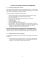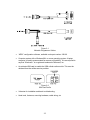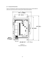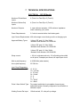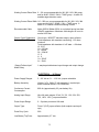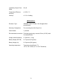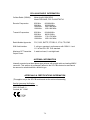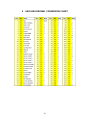
1
SIP-CB/a Survey Instrument Point Cellular / Battery-Powered / Analog Document: 900371 Revision: A May 25, 2008 WARNING: This product contains a radio-frequency transmitter, Motorola g24, Model F6413AAD, FCC ID # IHDT56FV2 The combined cable loss and antenna gain must not exceed 6.1dBi gain, and the antenna installation must provide a minimum separation distance of 20cm (8”) from users and nearby persons and must not be collocated or operating in conjunction with any other antenna or transmitter. Refer to Chapter-6 for additional safety information. COPYRIGHT 2008 by Metretek, Incorporated All rights to this document, domestic and international, are reserved by Metretek, Incorporated. No part of this publication may be reproduced, stored in a retrieval system, or transmitted in any form or by any means (electronic, mechanical, photocopying, recording, or otherwise) without the prior written permission of Metretek, Incorporated. Requests for permission to reproduce or distribute this manual should be addressed to: Metretek, Incorporated 305A East Drive Melbourne, Florida, USA 32904 ii TABLE OF CONTENTS 1 2 3 4 5 6 7 PRODUCT DESCRIPTION ....................................................................................1-1 1.1 Product Overview .........................................................................................1-1 1.2 Power Requirements ....................................................................................1-2 1.3 Enclosure .....................................................................................................1-2 1.4 DC-2000 Data Collection System.................................................................1-2 1.5 CSD versus Packet (Internet) Mode.............................................................1-3 1.5.1 CSD Mode ..............................................................................................1-3 1.5.2 Packet (Internet) Mode ...........................................................................1-4 1.6 Communications Scenarios..........................................................................1-6 INSTALLATION AND TECHNICAL INFORMATION ............................................2-1 2.1 Unpacking, Damage reports, Item List .........................................................2-1 2.2 Additional Items Required for Installation .....................................................2-1 2.3 Site Selection for Best Performance.............................................................2-3 2.4 Component Layout .......................................................................................2-4 2.5 Enclosure Dimensions..................................................................................2-5 2.6 Internal Wiring ..............................................................................................2-6 2.7 External Wiring .............................................................................................2-7 2.8 SIP-CB Module.............................................................................................2-8 2.8.1 SIM Card Installation ..............................................................................2-9 2.8.2 SIP-CB Battery Performance and Replacement ....................................2-9 2.8.3 Reset Pins ............................................................................................2-10 2.9 Low-Power Storage and Shipping Mode ....................................................2-11 2.10 Using the Internal Magnetic Switch to Place a Call ....................................2-12 2.11 Optional TAMPER Switch ..........................................................................2-13 2.12 ILI Board Details .........................................................................................2-14 2.12.1 ILI Power Supply Jumper Settings .......................................................2-15 2.12.2 ILI Analog Signal Range Jumper Settings............................................2-15 2.12.3 How the ILI Board Works......................................................................2-16 2.12.4 ILI Battery Performance and Replacement ..........................................2-17 CELLULAR SERVICE ...........................................................................................3-1 CONFIGURATION USING METRETEK PROGRAMMER (MP-32) ......................4-1 4.1 Time Interval Size.........................................................................................4-1 4.2 Input / Output Parameters ............................................................................4-2 4.2.1 Recommended Line Settings .................................................................4-3 4.2.2 “Description” Field ..................................................................................4-3 4.3 Options Configuration...................................................................................4-4 4.4 Serial Port Configuration ..............................................................................4-5 4.4.1 Maximum Packet Size ............................................................................4-5 DC-2000 DATA COLLECTION SYSTEM..............................................................5-1 5.1 Configuring the SIP-CB/a’s Pulse-Counting Inputs ......................................5-1 5.1.1 Deleting Unused Inputs ..........................................................................5-1 5.1.2 Defining the Interval Size........................................................................5-2 5.1.3 Defining the Units of Measure (Scaling Factor)......................................5-3 5.1.4 Configuring the SIP-CB/a’s Alarms ........................................................5-4 SAFETY, HAZARDOUS AREAS, ESD PRECAUTIONS ......................................6-1 6.1 Safety ...........................................................................................................6-1 6.2 ESD Handling Precautions ...........................................................................6-1 TECHNICAL SPECIFICATIONS ...........................................................................7-1 iii 8 9 ASCII-HEX-DECIMAL CONVERSION CHART.....................................................8-1 WARRANTY INFORMATION ................................................................................9-1 LIST OF TABLES ILI Power Supply Configuration Jumpers.....................................................................2-15 ILI Input Range Selection Jumpers ..............................................................................2-15 Recommended Input/Output Settings for the SIP-CB/a.................................................4-3 LIST OF FIGURES Data Collection System using the Internet.....................................................................1-5 Metretek Programmer Cables ........................................................................................2-2 SIM Card Profile.............................................................................................................2-2 Component Layout.........................................................................................................2-4 Enclosure Dimensions ...................................................................................................2-5 Internal Wiring Diagram .................................................................................................2-6 Routing of External Wires ..............................................................................................2-7 Figure 2-7 provides a view of the SIP-CB module, its battery and antenna...................2-8 View of SIP-CB Module .................................................................................................2-8 Installation of the SIM Card............................................................................................2-9 Location of SIP-CB/a Reset Pins .................................................................................2-10 Low-Power Storage Mode Jumper ..............................................................................2-11 Location of the Magnetic “Call” Switch.........................................................................2-12 ILI Board Layout...........................................................................................................2-14 Input / Output Configuration Parameters Screen ...........................................................4-2 Terminal Block Assignments versus Line Numbers in MP32.........................................4-2 Options Screen ..............................................................................................................4-4 Serial Port Configuration Screen ...................................................................................4-5 Device Configuration Screen/ Input Description ............................................................5-1 Data Input Configuration Screen....................................................................................5-2 Hardware Alarm Configuration Screen ..........................................................................5-4 iv Revision History Rev-A (May 25, 2008) Original release. v vi 1 PRODUCT DESCRIPTION The main processing module in this product is also used in other products and is known as the “SIP-CB”. This, combined with additional analog circuitry, forms a product called the “SIP-CB/a. 1.1 Product Overview Many metering devices generate electrical pulses to indicate what they are measuring. A gasoline pump might produce one pulse for every liter of fuel dispensed. A vending machine might generate one pulse for each beverage purchased. For these pulses to have meaning there must be a way to count them and store the totals for later processing. In the vending machine example this information might be gathered electronically at the end of each day to see if the machine needs to be refilled without the need to send a person to each site. Metretek’s SIP-CB/a is designed to count low-frequency pulses over a specific period of time ranging from 1 minute to 60 minutes and save the total count as one record. It then repeats this process for the next time period and can do this for hours, days or months at a time. The SIP-CB/a can count pulses from four independent sources simultaneously. The SIP-CB/a also has four other inputs for alarm or status processing. The Isolated Linear Integrator, or “ILI”, is a small circuit board that converts a steadystate (dc) analog voltage signal into a stream of digital pulses that the SIP-CB can count. The ILI can accept voltages up to 150 Vdc. The ILI can provide complete isolation between the voltages being measured and the SIP-CB. The SIP-CB/a can contain one or two ILI boards. At some point the SIP-CB/a must transmit its records and alarm status to a central computer system for processing and to make room for new records. Traditionally data logging devices have used wired telephone lines and modems to communicate with central computer systems. But in some cases the devices may have to be located in very remote locations and the cost of running phone lines to those locations may be quite high. Additionally the monthly cost of wired phone service has greatly increased. Operating as a wireless modem, a connection is made using a commercial GSM digital cellular phone network. The SIP-CB/a supports the four most common GSM bands: 850, 900, 1800 and 1900 MHz. It supports either circuit-switched data (CSD) or Internet (packet) communications if these services are offered by the cellular service providers. In addition to processing input signals the SIP-CB/a can produce four output signals. These signals can be controlled from the central computer and can be used to activate external equipment such as pumps, lights or audible alarms. Alternatively any output can replicate the signal that is present on any pulse or alarm input. This allows other pulse-counting or alarm-sensing equipment to have access to the same information. 1-1 1.2 Power Requirements The main processing module (SIP-CB) is powered from one 3.6V, 38 A/hr lithium battery pack. Battery life is primarily a function of the battery’s amp-hour rating, how often the SIP-CB/a is allowed to call the central computer and how often calls have to be repeated due to poor signal conditions. The radio consumes the most power. If the SIP-CB/a makes seven 1-minute calls per day you can expect a battery life of 2 years or more. Alternatively this module can be powered from a regulated and filtered 3.6Vdc power supply. This would be required if you wish to call or page the SIP-CB/a. In these cases the radio must remain powered up at all times and would quickly drain a battery. Each ILI board is powered by one 3.6V, 19 A/hr lithium battery pack. Service life is approximately 2.2 years. Two ILI boards can be operated from one battery but the service life will be reduced to about 1 year. Alternatively the ILI boards can be powered from a low-current dc power supply in the range of 3 – 12 Vdc. See Chapter-2 for more information about power sources. 1.3 Enclosure All components are housed in a weather resistant NEMA enclosure than can be locked for added security. There is one cable entry port on the bottom of the box. See Chapter-2 for dimensions and views. 1.4 DC-2000 Data Collection System Metretek offers a powerful data collection system called “DC-2000” that can collect information from thousands of devices, store their data in a database and present the results to you in a variety of formats. It can also notify you immediately when an alarm condition occurs. DC-2000 supports both CSD (circuit-switched data) and packet (Internet) connections. 1-2 1.5 CSD versus Packet (Internet) Mode The SIP-CB/a can communicate with the central computer’s modem using a circuitswitched data (CSD) connection or it can exchange information with the central computer over the Internet using “packet” mode. There are advantages and limitations to each method. 1.5.1 CSD Mode CSD mode is similar to two modems communicating over a wired telephone line. This is very similar to a “dial up” connection between your home computer and your Internet Service Provider. The cellular service provider has banks of analog modems available in their switching centers. When it detects a CSD call it connects one of its own modems to the wired line and dials the central computer’s modem. Data is transferred between the SIP-CB/a and the switching center over the radio link, and then between the switching center and the destination modem via wire. Cellular service providers often offer this service as an addon package to a standard “voice” account, and each call is measured and billed in terms of minutes used. Depending upon the frequency and length of the calls this service can become quite expensive. In situations in which the calls are long distance it may be possible to purchase plans that include free long distance in order to reduce costs. Some cellular service providers may not support “mobile-terminate” connections, which means the SIP-CB/a can place a call to the computer but cannot be called by the computer. However the central computer can “page” the SIP-CB/a by dialing its voice number or by sending it a text message. This will cause the SIP-CB/a to immediately call back to the central computer. Paging or dial-outs are not recommended for batteryoperated units because the radio must remain powered up at all times and will quickly drain the battery. CSD mode requires the use of a special Metretek modem chassis called a MODSMOD (modular smart modem). This chassis can hold up to 8 modem cards. The MODSMOD uses a special protocol known only to Metretek devices and will reject any calls that do not follow this format. The 8 channels can hold a combination of 1200, 2400 and 9600 bps cards. A 9600 bps card is required for cellular communications whereas the slower cards support the legacy wire line Metretek devices. See Figure 1-1 for a simple illustration of a wireless CSD connection. 1-3 Figure 1-1 Data Collection System using CSD 1.5.2 Packet (Internet) Mode Cellular service providers may offer access to the Internet using a service generally called “packet service”. On GSM networks this is called the general packet radio standard (GPRS). Data is exchanged in small blocks, or packets, with DC-2000. Cellular service providers may offer this service as an add-on package to a standard “voice” account, or may offer it as a stand-alone product. Each connection is usually measured and billed in terms of the amount of data exchanged each month. The amount of information exchanged on each call may range from several hundred bytes to 10’s of thousands of bytes, depending upon the information that is requested from the SIP-CB/a. It may be necessary to test the system for several months and then adjust the cellular account for the best cost based on your needs. For instance if you purchase one million bytes (1 Mb) per month but only use 100,000, you may be able to purchase a smaller and thus less expensive plan. For security reasons the SIP-CB/a cannot be contacted via the Internet because it only acts as a “client”. It is not listening for connection requests from other devices. Only an Internet “server” does that. However the central computer can “page” the SIP-CB/a by dialing its voice number or by sending it a text message. This will cause the SIP-CB/a to immediately call back to the central computer. Paging is not recommended for batteryoperated units because the radio must remain powered up at all times and will quickly drain the battery. 1-4 DC-2000 acts as an Internet server on your computer and thus must be allowed access to the outside world. Most corporate computer systems use firewall technology to prevent unauthorized and potentially damaging access from outside sources. To minimize potential invasion DC-2000 and the SIP-CB/a exchange private information using the 64-bit data encryption standard. If this exchange fails, the connection is immediately terminated. An Internet address and port number must be assigned to the computer running DC2000, and these numbers must be programmed into each SIP-CB/a. Your computer system’s administrator usually assigns the address and port number. When the SIPCB/a calls in it assigns itself what is known as a “source port” number. To further enhance security the SIP-CB/a can be assigned only one or a specific range of source port numbers and the firewall can be programmed to only allow these through. See Figure 1-2 for a simple illustration of a wireless Internet connection. Figure 1-2 Data Collection System using the Internet 1-5 1.6 Communications Scenarios There are several ways for the SIP-CB/a to communicate with the central computer: Scenario #1: The SIP-CB/a initiates its own call to the central computer • The SIP-CB/a determines that a call should be made due to an alarm condition or a regularly-scheduled call event. • The cellular radio on the SIP-CB/a is powered up and establishes a connection with the cellular phone network. • The SIP-CB/a initiates an outbound data call (CSD mode) or a packet (Internet) connection to the central computer, which is running DC-2000. • The central computer processes the SIP-CB/a’s data and stores it in a database structure format. • The SIP-CB/a is given new instructions including when to call next. The call is then terminated and the radio is powered down (for battery-operated units) or remains powered up to listen for pages (for externally-powered units). Scenario #2: The data collection computer initiates a data call to the SIP-CB/a in CSD mode. • The SIP-CB/a’s cellular radio is always powered up, is registered with the cellular network and is therefore always ‘listening’ for an incoming call. • The central computer dials the radio’s “data” number (this is known as a “mobileterminate” CSD connection). When the radio answers the call it will establish a link with the computer, which is running DC-2000. • The computer processes the meter’s data and stores it in a database structure format. • The SIP-CB/a is given new instructions including when to call next. The call is then terminated but the radio remains powered up to accept future calls. This configuration is not recommended for battery-operated units because the radio must remain powered up at all times and will quickly drain the battery. A full-time power supply is required for this mode. 1-6 Scenario #3: The data collection computer “pages” the SIP-CB/a and waits for the SIP-CB/a to call back. For security reasons the SIP-CB/a cannot be contacted via the Internet because it only acts as a “client”. It is not listening for connection requests from other devices. Only an Internet “server” does that. In CSD mode the cellular service provider may not support “mobile-terminate” connections, which means the SIP-CB/a can place a call to the central computer but cannot be called by the computer. In these cases the SIP-CB/a can be “paged”, which will cause the unit to call back immediately. • The SIP-CB/a cellular radio is always powered up, is registered with the cellular network and is therefore always ‘listening’ for an incoming call or page. • If the cellular account has been assigned a voice or data phone number, the computer calls that number. The SIP-CB/a answers the call and attempts to communicate with a modem (which is not there). After several seconds it hangs up and will immediately call the central computer as described in Scenario #1. • If the cellular account includes a feature called SMS (short message service, used for text messaging between cellular phones), the computer can send a text message to the SIP-CB/a. When the SIP-CB/a receives the message it will immediately call the central computer as described in Scenario #1. This configuration is not recommended for battery-operated units because the radio must remain powered up at all times and will quickly drain the battery. A full-time power supply is required for this mode. 1-7 1-8 2 INSTALLATION AND TECHNICAL INFORMATION 2.1 Unpacking, Damage reports, Item List Upon receipt inspect the SIP-CB/a for any potential shipping damage. If any damage is detected that can be attributed to the way the package was handled then a claim should be filed with the shipping agent as quickly as possible. A typical SIP-CB/a is provided with the following items: 1. 2. 3. 4. 5. 6. 7. 8. 9. 10. Main processing module with cellular radio and internal antenna (“SIP-CB”) One 3.6V, 38 A/hr lithium battery pack for the main module. One or two ILI boards One or two 3.6V, 19 A/hr lithium battery pack(s) for the ILI board(s). Inter-board connection cables. Cable entry gland. NEMA-rated outdoor enclosure Optional TAMPER (open door) detect switch Manual 900366. This document describes the main processing unit (SIP-CB). Manual 900371 (this document). Normally only one manual is included with each shipment rather than with each unit. Additional manuals can be ordered separately or obtained in PDF file format upon request. Note: The items listed above may vary depending on what was requested with the original purchase order. Refer to the shipping document or the purchase order for a precise record when inspecting the package contents. Lithium batteries are usually shipped in separate containers to comply with hazardous goods transportation rules. 2.2 Additional Items Required for Installation Several additional tools and items will be required before proceeding with the field site installation: • Programming cables as illustrated in Figure 2-1. Part number 1002-0299C-001 for computers with serial (RS-232) com ports or 1002-0344-001 for those with USB ports. Only one cable is required to program all units. 2-1 Figure 2-1 Metretek Programmer Cables • “MP32” configuration software, available under part number 100160. • Computer system with a Windows-98 or newer operating system. A laptop computer is usually recommended for reasons of portability. We are required to say that “Windows” is a registered trademark of Microsoft, Inc. • An activated SIM card to enable the GSM cellular radio module. This must be obtained from the cellular service provider. Figure 2-2 SIM Card Profile • Voltmeter for installation and basic troubleshooting. • Hand tools, fasteners, mounting hardware, cable wiring, etc 2-2 2.3 Site Selection for Best Performance WARNING: This product contains a radio-frequency transmitter, Motorola g24, Model F6413AAD, FCC ID # IHDT56FV2 The combined cable loss and antenna gain must not exceed 6.1dBi gain, and the antenna installation must provide a minimum separation distance of 20cm (8”) from users and nearby persons and must not be collocated or operating in conjunction with any other antenna or transmitter. Field site selection for a cellular communications product requires additional consideration with regard to wireless communications. • Raise the elevation as high as practical from the ground. • Avoid mounting the unit to the side of a metal shed or similar structure since metal is a very effective shield against the desired radio signal. Chain link fences are normally not a problem. • Avoid mounting the product in a location where the antenna is in close proximity to a sensitive measurement instrument such as a Rosemont transducer. The strong radio signal from the cellular transmitter could possibly degrade the accuracy of these precision instruments. Conversely, nearby electronic equipment may interfere with the operation of the cellular radio. Depending on the signal strength for a given location it may be possible to ignore some of these suggestions and still obtain good performance. This will vary from one site to the next, just as the reception quality of a handheld cellular phone will vary. The SIP-CB/a has several LED indicators that will help you determine if the signal strength is adequate. You might be able to use your own personal cell phone as a signal strength gauge. However each service provider has its own frequencies and towers, so make sure that your cell phone and the SIP-CB/a use the same carrier, otherwise you might be misled into thinking that the site you’ve chosen is adequate when indeed it is not. 2-3 2.4 Component Layout Figure 2-3 Component Layout 2-4 2.5 Enclosure Dimensions Figure 2-4 illustrates the maximum external dimensions that must be accommodated to mount the enclosure as well as mounting hole locations and diameters. Figure 2-4 Enclosure Dimensions 2-5 2.6 Internal Wiring Figure 2-5 Internal Wiring Diagram 2-6 2.7 External Wiring There are three entry holes at the bottom of the enclosure, but only one is used. Inside the cable gland (also called a “cord grip”) is a rubber insert that compresses around the wires as the nut is turned clockwise. This provides a barrier against moisture and insects. Figure 2-6 Routing of External Wires 2-7 2.8 SIP-CB Module Please refer to Chapter-2 of the SIP-CB User’s Manual, Document 900366, for a complete discussion about the SIP-CB module. Figure 2-7 is a view of the SIP-CB module, its battery and antenna. Figure 2-7 View of SIP-CB Module Installation of the SIM card is straightforward as illustrated in Figure 2-8. Note that the SIM card has a chamfered corner to indicate the correct installation direction. 2-8 2.8.1 SIM Card Installation Figure 2-8 Installation of the SIM Card Never remove or install a SIM card while the LEDs are lit. This could damage the SIM card or radio. 2.8.2 SIP-CB Battery Performance and Replacement Lithium battery technology is commonly used for these types of applications due to their high energy capacity, low self-discharge rate and reliable performance at hot or cold temperatures. It should be stressed here that disconnection of the lithium battery pack does not completely power down the SIP-CB board electronics. This is due to a secondary power source called a super capacitor (similar to a rechargeable battery) that is a part of the SIP-CB module. Pulse counting and outputs will continue to operate without interruption while the battery pack is being replaced. This ensures that no data is lost during the exchange process. However cellular calls are not allowed when the main lithium battery is disconnected. Battery voltage changes with temperature. If the unit is located in very cold or hot climates you may receive occasional low-battery alarms as the temperature changes. However, any low-battery alarm should be taken seriously and the battery should be replaced soon. If the battery gets too low the unit may no longer be able to make calls and may not be able to count or save its pulse data. 2-9 The voltage of the battery under light load is about 3.6V. When the SIP-CB is charging its internal super capacitor the voltage can drop down to nearly 2.3V or possibly lower in extremely cold or hot environments. To prevent false low-battery alarms the low-battery alarm point should be set between 2.1V and 1.9V. When replacing a battery you will need to cut the cable tie. A new cable tie is recommended to keep the new battery from damaging other components. Lithium batteries are dangerous and must be disposed of properly! 2.8.3 Reset Pins To perform a complete reset use a small blade screwdriver or coin to short out the two pins shown in Figure 2-9. Figure 2-9 Location of SIP-CB/a Reset Pins A reset will cause pulse data to be lost and the unit’s time-of-day to be reset. This will cause the SIP-CB/a to call the data collection system to report a “unit reset” alarm. 2-10 2.9 Low-Power Storage and Shipping Mode The internal “super capacitor” in the SIP-CB module is fully charged prior to shipment and cannot be disconnected. The circuit is operational even without the lithium battery pack connected. Deeply discharging the capacitor is undesirable. It reduces the overall life expectancy of the capacitor and places great demands on the lithium battery the first time it’s connected. During shipping and storage the SIP-CB is placed into a very low power state. To activate this mode a small jumper block is installed between the first two pins of the programming port, and the “RESET” jumper is momentarily shorted. See Figure 2-10. The board will flash the red LED three times, and repeat this another 2 times, and then enter the very low-power mode. While in this mode the SIP-CB/a does not count pulses, process alarms or place cellular calls. The only way to deactivate this mode is to remove the jumper and momentarily short the “RESET” jumper. Figure 2-10 Low-Power Storage Mode Jumper You should also disconnect the battery packs from the ILI boards. 2-11 2.10 Using the Internal Magnetic Switch to Place a Call A magnetic switch is wired in parallel with TB3-3 & TB3-4 (labeled CALL+ and CALL-) on the SIP-CB module. The switch is located in the bottom of the module and is a normally open (Form-A) magnetic reed switch. This allows you to start a call by momentarily placing a strong magnet near the module as indicated in Figure 2-11. For this to work Line #12 on the SIP-CB/a must be configured as a Form-A alarm input and should be programmed to place an immediate call when active. See Chapter-4 about programming. Figure 2-11 Location of the Magnetic “Call” Switch 2-12 2.11 Optional TAMPER Switch An optional magnetic switch can be installed to detect when the enclosure’s door has been opened. See Figure 2-3 for its location. The actual switch is located on the righthand side of the enclosure and an actuating magnet is located on the left-hand side. It is connected to the TAMP+ and TAMP- inputs on the SIP-CB module. The SIP-CB/a reports this as a “TAMPER” alarm to the DC-2000 data collection system. Using the MP32 configuration program the SIP-CB/a can be programmed to place a call immediately when the door is opened, when it is closed or both. The data collection system DC-2000 can override the immediate call feature. If the immediate call feature is disabled the SIP-CB/a will still report the event on the next call, even if that call occurs hours after the actual event. The SIP-CB/a will also report the time-of-day when the first event occurred. When the door is closed the switch is in a closed state. Therefore it is important to program this input as a Form-B (normally closed) switch. If the TAMPER feature is not needed you can disconnect the leads and use the TAMP+ and TAMP- inputs for another purpose and can change it to Form-A if needed. The SIP-CB will still report this as a “TAMPER” alarm to the DC-2000 data collection system. However you can change its description in DC-2000 to something else, such as “Pump Failure” or “Water Level Too Low”. 2-13 2.12 ILI Board Details The ILI board is a calibrated device. Do not readjust or replace any components! The SIP-CB/a contains one or two Isolated Linear Integrator (“ILI”) circuit boards, one for each analog signal to be measured. One of these boards is shown in Figure 2-12. Figure 2-12 ILI Board Layout Each ILI board operates from its own battery. This ensures complete isolation between the ILI and the SIP-CB, and between each ILI board. Isolation becomes a very important issue when measuring high voltage signals, or when the “ground” reference point is well above or below 0V. 2-14 2.12.1 ILI Power Supply Jumper Settings The ILI boards require an independent power source in order to maintain complete isolation between the signals being measured and the SIP-CB module. The ILI will accept power supply voltages between 3 Vdc and 12 Vdc. Several jumpers must be set to the proper positions as shown in the following table: Power Supply Voltage Range 3 – 6.0 Vdc 6.1 – 12.0 Vdc JP1 JP4 IN OUT OUT IN Table 2-1 ILI Power Supply Configuration Jumpers NOTE Each ILI board in a standard SIP-CB/a is supplied with its own 3.6 Vdc lithium battery. The JP1 and JP4 jumpers are configured at the factory for this arrangement. 2.12.2 ILI Analog Signal Range Jumper Settings To measure the analog signal with the best accuracy and resolution, choose the closest but next highest range shown in the next table: For instance, if the signal will reach 6 V, then choose the 12 V range. Full Scale Input Voltage 0 to +0.050 V 0 to +3 V 0 to +5 V 0 to +12 V 0 to +24 V 0 to +50 V 0 to +75 V 0 to +100 V 0 to +150 V JP2 A A B C D E F G H Table 2-2 ILI Input Range Selection Jumpers 2-15 JP3 A-B B-C B-C B-C B-C B-C B-C B-C B-C 2.12.3 How the ILI Board Works With jumper JP1 out and JP4 in power supply voltages between 6.1 and 12 Vdc are simply regulated down to +5 Vdc. With jumper JP1 in and JP4 out voltages between 3 and 6 Vdc are first doubled by a switched-capacitor boost regulator, then regulated down to +5V. A switched-capacitor inverter generates –5V from the +5V supply to power the analog circuitry. An additional circuit generates a stable 2.7 Vdc reference voltage that is used in several places. When the power supply drops to a value of about 2.7V, an optically coupled switch will turn on for approximately 60 milliseconds. The output of this switch is connected to an alarm input on the SIP-CB module. When the SIP-CB senses this event it will call in to report the condition or report it on the next call, depending upon how the unit is programmed. The battery should be replaced as soon as possible. The analog signal to be measured is connected to terminal block TB1, Positions 1 (+) and 2 (-). Depending upon the setting of jumpers JP2 and JP3, the signal will either be amplified or reduced with a certain degree of precision. This signal then controls a precision timing circuit that generates a linear pulse stream of 0 to 5 pulses-per-second. This corresponds to an analog input range of 0V to full scale. The pulse train is used to drive several optically coupled switches. To minimize current drain the pulses are kept as short, approximately 400 microseconds each. The opto switches are arranged as a simple logic circuit (“flip-flop”) that produces two outputs, each with a 50% duty cycle and of opposite polarity to each other. This is known as a Form-C or “KYZ” arrangement. Each output needs to be pulled up to a voltage source through a resistor in order to operate correctly. This is provided by the SIP-CB module. The outputs of the two ILI boards are connected to the pulse-counting inputs on the SIPCB module. The SIP-CB is configured to count these pulses over a certain time interval and save the totals as records in memory. A large interval will allow records to be stored over a longer period of time. A short interval will allow trends to be observed with better resolution. The data collection software can convert these time-tagged interval (TTI) readings back into voltage readings using a simple formula. As an example assume that the ILI has been configured for a full-scale range of 75V. The ILI board will produce 0 pulses for 0V and up to 5 pulses per second at 75V. Suppose over a 15-minute (900 second) period the final count is 2760. Voltage = (final count) x (full scale range) -----------------------------------------------------------------------(Interval in seconds) x (pulses per second at full scale) Voltage = (2760) x (75V) --------------------------------------------------(900 seconds) x (5 pulses per second) Voltage = 46V 2-16 2.12.4 ILI Battery Performance and Replacement Battery voltage changes with temperature. If the unit is located in very cold or hot climates you may receive occasional low-battery alarms as the temperature changes. However, any low-battery alarm should be taken seriously and the battery should be replaced soon. If the battery gets too low the ILI board may no longer be able to generate pulse data or the readings may become inaccurate. As mentioned earlier the ILI board reports a low-battery alarm when the voltage drops below 2.7V. It only does this once. If the voltage increases above 2.7V, another alarm will be reported when it again falls below 2.7V. You should expect over two years of battery life based on a 19 A/hr lithium pack. The ILI shuts down during battery replacement. You may lose a few pulses during this time. Also, the SIP-CB/a may report one low-battery alarm when the new battery is plugged in. When replacing a battery you will need to cut the cable tie. A new cable tie is recommended to keep the new battery from damaging other components. Lithium batteries are dangerous and must be disposed of properly! 2-17 2-18 3 CELLULAR SERVICE Please refer to Chapter-3 of the SIP-CB User’s Manual, Document 900366, for a complete discussion about purchasing cellular service. 3-1 3-2 4 CONFIGURATION USING METRETEK PROGRAMMER (MP-32) Please refer to Chapter-4 of the SIP-CB User’s Manual, Document 900366, for a more comprehensive discussion about programming the SIP-CB. Here we discuss only those parameters that are necessary for the SIP-CB/a to make proper measurements. 4.1 Time Interval Size The SIP-CB/a counts pulses from the ILI boards over a specific time interval and then saves the total as one record. It then starts the counting process over for the next time interval and this process continues indefinitely. The time interval can be 1, 2, 3, 5, 6, 10, 12, 15, 20, 30 or 60 minutes. A shorter time period allows you to observe small changes with more detail. But it also consumes memory more quickly, causing the SIP-CB/a to need to communicate with the data collection system more frequently. This can have an impact on both battery life and the cost of the cellular service. The SIP-CB/a has the capacity to save a total of 30,000 records before it starts to overwrite the oldest records. This area is divided equally between all active pulsecounting channels. If only one channel is used for pulse-counting then all 30,000 memory locations will be used for that channel. If using a 10-minute interval it would take a little over 200 days to reach the end of the memory. If 4 channels are active then each channel is allocated 7500 records. If using a 10-minute interval it would take about 50 days to reach the end of the memory. If some of the pulse / alarm inputs are not being used for pulse-counting then they should be programmed as alarm inputs (even if they are not going to be used for alarms). This will cause the memory to be divided between only those channels that will actually be counting pulses. DC-2000 must also be configured with the same interval or the calls from the SIP-CB/a will be rejected. See Chapter-5 for more details about DC-2000. 4-1 4.2 Input / Output Parameters We now concentrate on the portion of the screen used to define how the various inputs and outputs are configured and reported to DC-2000. MP32 refers to “Line Numbers” for the 12 possible input and output lines. See Figure 42 to determine where those lines are on the SIP-CB’s terminal blocks. Figure 4-1 Input / Output Configuration Parameters Screen Figure 4-2 Terminal Block Assignments versus Line Numbers in MP32 4-2 4.2.1 Recommended Line Settings See Figure 2-5 in Chapter-2 to see how the SIP-CB/a is wired. Program the lines as they appear in Table 4-1. LINE SETTING ADDITIONAL SETTINGS Line #1 Pulse Counting Input (for ILI-1(Z)) Pulse Counting Input (for ILI-1(Y)) Pulse Counting Input (for ILI-2(Z)) Pulse Counting Input (for ILI-2(Y)) Alarm (low battery on ILI-1) Alarm (low battery on ILI-2) Output Follows Input #1 (optional) Output Follows Input #3 (optional) Output Under Host Control (optional) Output Under Host Control (optional) Alarm (Tamper Switch) Alarm (Internal “Call” Mag Switch) Form-C(Z), Debounce = 0 Line #2 Line #3 Line #4 Line #5 Line #6 Line #7 Line #8 Line #9 Line #10 Line #11 Line #12 Form-C(Y), Debounce = 0 Form-C(Z), Debounce = 0 Form-C(Y), Debounce = 0 Form-A, Debounce = 2, Immediate Call on Alarm going Active Form-A, Debounce = 2, Immediate Call on Alarm going Active Replicates the ILI-1 pulse stream. Replicates the ILI-2 pulse stream. Can be used to remotely control an external piece of equipment Can be used to remotely control an external piece of equipment Form-B, Debounce = 50, Immediate Call on Alarm going Active Form-A, Debounce = 3, Immediate Call on Alarm going Active Table 4-1 Recommended Input/Output Settings for the SIP-CB/a 4.2.2 “Description” Field You can enter a verbal description (15 characters max) for each input and output. These descriptions are for your reference only and are not reported to the data collection system. 4-3 4.3 Options Configuration Select the Options tab to continue the configuration. Change the configuration items to match those in Figure 4-3. Figure 4-3 Options Screen NOTE: To change the Sample Pulse Width and Sample Rate fields, hold down the CTRL key on the keyboard, point to the field and double click the left mouse key. This unlocks the field and allows you to enter a different value. 4-4 4.4 Serial Port Configuration Some other Metretek devices support serial communications but not the SIP-CB/a. However one setting on the Serial Port Configuration screen is needed for packet (Internet) connections. Figure 4-4 Serial Port Configuration Screen 4.4.1 Maximum Packet Size When the SIP-CB/a has a large volume of time-tagged interval (pulse) data to transmit it is necessary to send it in many smaller “packets” in order to comply with Internet rules. Each packet contains the actual data plus error-checking and routing information. This “overhead” information is usually the same size regardless of the data size. Therefore it is best to make the data portion as large as possible. This results in the shortest transmission time, especially important in battery-operated devices. In SIP-CB/a’s maximum packet size is 1024 bytes. However when network traffic is heavy or if signal conditions are less than optimal smaller packets may stand a better chance of being delivered than larger ones. If too many calls are failing this could be a factor. You may have to experiment with the packet size to obtain better performance. 4-5 4-6 5 DC-2000 DATA COLLECTION SYSTEM Please refer to Chapter-5 of the SIP-CB User’s Manual, Document 900366, for a more comprehensive discussion about DC-2000. Here we discuss only those parameters that are necessary for the SIP-CB/a to operate correctly. 5.1 5.1.1 Configuring the SIP-CB/a’s Pulse-Counting Inputs Deleting Unused Inputs On the Input Description tab delete Inputs #3 and #4. Figure 5-1 Device Configuration Screen/ Input Description 5-1 5.1.2 Defining the Interval Size Next you must define the pulse-counting interval, which applies to all channels that are configured for pulse-counting. Highlight one of the remaining channels on the screen and select the CONFIGURE button (or simply double-click on the selected channel). The following screen will appear. Figure 5-2 Data Input Configuration Screen Select the Input Definition tab. Here you can match the time interval to that which was programmed into the SIP-CB/a. This will apply to both ILI boards. You can also change the description of each channel and select which type of data to save. 5-2 5.1.3 Defining the Units of Measure (Scaling Factor) The UNITS screen allows you to convert tagged interval (TTI) readings to something more meaningful. Since the ILI board measures voltage, it would be of more use to have the readings appear in terms of volts. As mentioned earlier each ILI board produces a number of pulses per second, the rate of which is directly proportional to the signal being measured. The ILI produces a maximum of 5 pulses per second for a full-scale input voltage. A time-tagged interval (TTI) reading consists of the total number of pulses produced over the period of time defined by the Interval Resolution. As an example assume that the ILI has been configured for a full-scale range of 24V. The ILI board will produce 0 pulses for 0V and up to 5 pulses per second at 24V. Suppose over a 5-minute (300 second) period the final count is 1100. Voltage = (final count) x (full scale range) -----------------------------------------------------------------------(Interval in seconds) x (pulses per second at full scale) Voltage = (1100) x (24V) --------------------------------------------------(300 seconds) x (5 pulses per second) Voltage = 17.6V In this example a Multiplier of 0.016 will produce the desired results. The Multiplier is calculated as follows: Multiplier = (full scale range) -----------------------------------------------------------------------(Interval in seconds) x (pulses per second at full scale) Multiplier = (24V) ---------------------------------------------------(300 seconds) x (5 pulses per second) Multiplier = 0.016 Voltage = 1100 counts x 0.016 = 17.6V. 5-3 5.1.4 Configuring the SIP-CB/a’s Alarms Go back to the device configuration screen (Figure 5-1) and select the Hardware Alarms tab. Figure 5-3 Hardware Alarm Configuration Screen The SIP-CB/a is capable of reporting a number of alarm conditions. The SIP-CB/a can be configured to call immediately when an alarm condition occurs or to simply report it on the next call. This screen allows you to configure how alarms are reported to DC2000 by the SIP-CB/a and by DC-2000 to you. It also allows you to change the verbal description of each alarm. For instance the generic “Customer Alarm-1” description might be changed to “ILI-1 Low Battery”. 5-4 Even if the SIP-CB/a is configured to call immediately when an alarm occurs, in some cases DC-2000 can override this and simply have the alarm reported on the next scheduled call. For any alarm that requires an immediate call check the Immediate Alarm Notification box. Some alarms cannot be overridden because they are too important to ignore, such as a unit reset alarm. Make sure you have also programmed the SIP-CB/a to place an immediate call for these alarms. See Chapter-4. The Nuisance Limit can be used to disable calls due to a repeating alarm condition, such as a low-battery alarm for the SIP-CB’s battery. Until the battery is replaced the SIPCB/a will keep calling in every couple of minutes to report the alarm. This is especially undesirable for battery-operated units because each call consumes a lot of power. But if you set the Nuisance Limit to 3 then DC-2000 will instruct the SIP-CB/a to stop calling in after the third report of the same alarm. Later, when the SIP-CB/a calls in at its regularly-scheduled time the Nuisance Limit will be reset and the unit will again be allowed to report the alarm up to 3 times until the next scheduled call. Note: Changes made to any alarm configuration will not go into effect until the next communication with the SIP-CB/a. Here is a general list of the alarms reported by the SIP-CB/a. Tamper Detect Alarm: Occurs whenever the door of the enclosure is opened. This is reported when the optional TAMPER detect switch is installed. Magnetic Switch Alarm: Inside the SIP-CB module is a Form-A magnetically-operated switch that is also connected to Line #12. It can be triggered using a magnet as seen back in Figure 2-11. You can also wire an external switch to this input if the magnetic feature is not needed. Customer Alarm 1: Occurs when the battery for ILI #1 is low. See Chapter-2 about how this alarm is generated. Customer Alarm 2: Occurs when the battery for ILI #2 is low. See Chapter-2 about how this alarm is generated. AC-Off Alarm: Not reported. AC-On Alarm: Not reported. Unit Reset Alarm: Occurs if the SIP-CB/a has been reset. A reset can be caused by the following conditions: a) The reset pins are shorted together (see Figure 2-9). b) The board’s configuration memory or operating code has been changed or read using the programming cable and MP32 software. c) The battery is nearly exhausted and can no longer support the current required by the board. 5-5 Call Retry Alarm: Occurs if a previous call attempt failed. Numerous Call Retry alarms may be an indication of network problems or that the unit is located in a marginal reception area. It may also happen if too many units are programmed to call DC-2000 at the same time. Queue Full Alarm: If pulse data is not collected often enough there is a chance that the oldest data may be lost due to insufficient memory. This memory is referred to as the “queue” and the SIP-CB/a will call in to report a “Queue Full” alarm when a certain percentage of the queue contains new records. This defaults to 75% but you can change it using MP32. Clock Resync Alarm: The SIP-CB/a’s time-of-day clock is updated each time it calls in to DC-2000. A Clock Resync alarm is reported if the SIP-CB/a’s clock has been corrected by more than ±20 seconds, and will be reported on the next call. There will always be a Clock Resync alarm reported on the first call after a unit reset call. Frequent Clock Resync alarms may indicate one of the following problems: a) The SIP-CB/a cannot properly keep time due to a hardware problem. b) The time given to the SIP-CB/a is taken from the computer’s time-of-day clock. This alarm may indicate that the computer’s clock is inaccurate (slow, fast or has been changed since the last call, such as a daylight savings time (DST) change). c) If the SIP-CB/a is programmed to call more than one computer, and the computers’ clocks are different by more than 20 seconds, this will cause a Clock Resync alarm. d) During packet (Internet) connections DC-2000 prepares the message containing the new time-of-day and sends it to the SIP-CB/a. If a packet does not arrive after a certain amount of time, the same packet is retransmitted. This will be repeated several more times before the connection is terminated. If it takes over 20 seconds to deliver the packet, then the time in the message will be 20 seconds older than the SIP-CB/a’s time. Remote Daily Volume Low Input-1,2: Occurs if the daily total is below the user-defined limits for ILI #1 or #2 respectively. Remote Daily Volume High Input-1,2: Occurs if the daily total is above the user-defined limits for ILI #1 or #2 respectively. Remote TTI Consumption Low Input-1,2: Occurs if an interval reading is below the userdefined limits for ILI #1 or #2 respectively.. Remote TTI Consumption High Input-1,2: Occurs if an interval reading is above the userdefined limits for ILI #1 or #2 respectively. Remote Daily Volume Low Input-3,4: Not reported. Remote Daily Volume High Input-3,4: Not reported. 5-6 Remote TTI Consumption Low Input-3,4: Not reported. Remote TTI Consumption High Input-3,4: Not reported. Low Battery Alarm: This alarm indicates that the main battery pack in the SIP-CB/a needs to be replaced as soon as possible. The voltage level at which the alarm will occur is programmed using MP32 (see Chapter-4). The battery should be changed as soon as possible to continue uninterrupted service. KYZ-1 Input Failure: Not reported. KYZ-2 Input Failure: Indicates a problem with ILI #1 or its wiring. KYZ-3 Input Failure: Not reported. KYZ-4 Input Failure: Indicates a problem with ILI #2 or its wiring. 5-7 5-8 6 SAFETY, HAZARDOUS AREAS, ESD PRECAUTIONS 6.1 Safety WARNING: This product contains a radio-frequency transmitter, Motorola g24, Model F6413AAD, FCC ID # IHDT56FV2 The combined cable loss and antenna gain must not exceed 6.1dBi gain, and the antenna installation must provide a minimum separation distance of 20cm (8”) from users and nearby persons and must not be collocated or operating in conjunction with any other antenna or transmitter. 6.2 ESD Handling Precautions Any electronics device contains components sensitive to ESD (electrostatic discharge). For example people experience up to 35kV ESD, typically while walking on a carpet in low humidity environments. In the same manner many electronic components can be damaged by less than 1000 volts of ESD. For this reason you must observe the following handling precautions when servicing this equipment: • • • • • • • Always wear a conductive wrist strap. Eliminate static generators (plastics, styrofoam, and so on) in the work area. Remove nylon or polyester jackets, roll up long sleeves, and remove or tie back loose hanging neckties, jewelry, and long hair. Store and transport all static sensitive components in ESD protective containers. Disconnect all power from the unit before ESD sensitive components are removed or inserted, unless noted. Use a static safeguarded workstation, which can be set up by using an anti-static kit (Motorola part number 0180386A82). This kit includes a writes strap, two ground cords, a static control tablemat, and a static control floor mat. The Motorola part number for a replacement wrist strap that connects to the tablemat is 4280385A59. When anti-static facilities are unavailable, use the following technique to minimize the chance of damaging the equipment: o Let the static sensitive component rest on a conductive surface when you are not holding it. o When setting down or picking up the static sensitive component, make skin contact with a conductive work surface first and maintain this contact while handling the component. 6-1 o If possible, maintain relative humidity of 70-75% in development labs and service shops. 6-2 7 TECHNICAL SPECIFICATIONS ELECTRICAL – SIP-CB Module Number of Pulse/Alarm Inputs: 4 (Form-A or Form-B) or 2 (Form-C) Number of Alarm-Only Inputs: 4 (Form-A or Form-B) or 2 (Form-C) Number of Outputs: 4, open collector transistor, 133Ω minimum impedance when conducting (“on”) state. Power Requirements: 3.6 volts dc nominal with a fresh battery pack. Input Current Requirements: 400 mA average current during a call or a charging cycle Approved Battery Types: Lithium ‘DD’ pack, 3.6 Vdc, 38AHr Metretek Stock Number 1011-0044-001 Lithium ‘DD’ pack, 3.6 Vdc, 38AHr Metretek Stock Number 1011-0046-001 Lithium ‘DD’ pack, 3.6 Vdc, 38AHr Metretek Stock Number 1001-0048-001 Sleep current: < 150 uA, originate mode only, 2.5 mS wetting pulse width on all inputs, 4 samples per second, all inputs open circuit. Main crystal frequency: 4.91520 MHz (when awake). Aux crystal frequency: 32.768 kHz. Input Circuit Parameters Terminal Block TB1 & TB3: Ui: 8.71V Uo: 6.51Vdc Io: 57.1mA Po: 93mW Ci: 0 Li: 0 Co: 500uF Lo: 40mH Pulse / Alarm Switch Type: Dry contact switch that is not capable of sourcing any appreciable power. Normally composed of a reed switch or transistor output. Wetting Current Per Input: 100uA nominal, 3.3 volts pull-up voltage. 7-1 Wetting Current Pulse Rate: 0 – 50, user programmable for IN1/ IN2 / IN3 / IN4 group and for ALM1 / ALM2 / CALL / TAMP group. A value of 0 enables edge-detection mode. Wetting Current Pulse Width: 0.0 – 950 ms, user programmable for IN1/ IN2 / IN3 / IN4 group and for ALM1 / ALM2 / CALL / TAMP group. A value of 0.0 creates continuous wetting current. Recommended Cable: Alpha 6300/4, Belden 9534, or equivalent having less than 100pF/ft capacitance. Maximum cable length run is not to exceed 1000 feet. Output Circuit Parameters: Terminal Block TB2: Circuit type: MOSFET transistor output, open collector. Total impedance with transistor conducting: 133 ohms minimum. Total impedance with transistor in 'off' state: >1M ohms. Ui: 9.5V Uo: 6.51Vdc Io: 103mA Po: 168mW Ci: 0 Li: 0 Co: 500uF Lo: 13mH “Output-Follows-Input” Mode Delay: 1 sample period between input change and output change ELECTRICAL – ILI Board Power Supply Ranges: 3 – 6.0 Vdc or 6.1 – 12.0 Vdc, jumper-selectable Battery Assembly: Lithium: 3.6V, 19Ahr ‘D’ cell assembly, 1 required per board, Metretek Stock # 1011-0049-001 Continuous Current Consumption: 800 uA (approximately 2.2 year battery life) Analog Input Range: Nine full-scale ranges: 50 mV, 3V, 5V, 12V, 24V, 50V, 75V, 100V, 150V , jumper-selectable Pulse Output Range: 0 – 5 pulses per second full scale Output Type: Form-C (KYZ), open-collector (both outputs require pullups) Pulse Duty Cycle: 50% Low Battery Trip Point: Approximately 2.7 Vdc. 7-2 Low Battery Output Pulse Width: 60 mS Temperature Effects on Accuracy: ± 0.03% / ºC Linearity: ± 0.1% of reading MECHANICAL Enclosure Type: NEMA4X, UL94 V-O rated, 10% fiberglass-filled polycarbonate. Mounting Configuration: Four mounting feet (See Figure 2-4) Cable Glands: 1 provided Recommended screwdriver: Flat blade type having a nominal 3.5mm (0.138") width for terminal blocks: Weight (without batteries): 2.5 pounds (1.13 kg) Battery Weight (SIP-CB): 0.47 pounds (213 grams) Battery Weight (ILI): 0.22 pounds (99.8 grams) Operating temperature: Temperature classification T4 -20° to +40° Celsius (-4° to +104° Fahrenheit) 7-3 CELLULAR RADIO INFORMATION Cellular Radio (GSM24): Motorola g24 GSM GPRS Model F6413AAD, FCC ID # IHDT56FV2 Receive Frequencies: 850 MHz: 900 MHz: 1800 MHz: 1900 MHz: 869-894 MHz 925-960 MHz 1805-1880 MHz 1930-1990 MHz Transmit Frequencies: 850 MHz: 900 MHz: 1800 MHz: 1900 MHz: 824-849 MHz 880-915 MHz 1710-1785 MHz 1850-1910 MHz Radio Module Approvals: FCC, DOC, R&TTE, PTCRB, IC, CTIA, FTA, EMC SIM Card Interface: 3 volt type, operates in conformance with GSM 11.1 and 11.2 of the ISO / IEC 7816 standard. Maximum RF Transmitter Output Power: 2 watts low band, 1 watt high band ANTENNA INFORMATION Internally mounted quad band planar type antenna with coaxial cable and mating MMCX connector. This antenna is permanently affixed to the SIP-CB/a electronics and cannot be removed or substituted with a different type. APPROVALS & CERTIFICATIONS INFORMATION (This applies only to the SIP-CB module and not the entire unit assembly) Quality Assurance Notification: Intertek Testing Services N.A., Inc. 3933 US Route 11 Cortland, NY 13045 7-4 8 ASCII-HEX-DECIMAL CONVERSION CHART 8-1 9 WARRANTY INFORMATION The seller warrants its hardware to be free from defects in material and workmanship under normal and proper use for a period of 12 months from the date the hardware is shipped from Metretek, Incorporated. The seller’s sole liability and the buyer’s sole remedy for any breach of the foregoing provision is, at the seller’s option, the timely no-charge repair or replacement of any defective hardware or part that Metretek inspects and finds reasonable evidence that a defect in material or workmanship exists. The buyer shall provide the labor required to remove the defective hardware and install its replacement at no charge to the seller. The equipment will be shipped to the seller at the buyer’s expense. The replacement or repaired equipment will be shipped to the buyer at the seller’s expense. Warranty claims to be honored under this warranty must be made promptly. Such claims shall specify the nature and details of the claim, the date that the cause of the claim was first observed, and the affected equipment’s unit serial number. Defective equipment shall not be returned to the seller’s factory without prior authorization from the seller. A copy of the claim’s documentation must be attached to the defective equipment and sent to the seller’s manufacturing facility. Defective components replaced under this warranty shall become the property of the seller. The seller makes no representation or warranty other than those set forth in this agreement. THE WARRANTY STATED HEREIN IS EXPRESSLY IN LIEU OF ALL WARRANTIES, EXPRESSED OR IMPLIED, INCLUDING BUT NOT LIMITED TO, ANY EXPRESSED OR IMPLIED WARRANTY OF MERCHANTABILITY OR FITNESS FOR A PARTICULAR PURPOSE. SUCH WARRANTY CONSTITUTES THE ONLY WARRANTY MADE BY THE SELLER WITH RESPECT TO THIS AGREEMENT, THE EQUIPMENT UNITS, OR THE SERVICES TO BE SUPPLIED HEREBY. THE SELLER SHALL NOT BE LIABLE FOR ANY INCIDENTAL OR CONSEQUENTIAL DAMAGES OF ANY KIND. This warranty will not extend to equipment subjected to accident, to misuse, or to alterations/repair not made and documented in writing by Metretek. Returns Procedure (North America) If it has been determined through troubleshooting that the problem cannot be resolved without returning the equipment for repair, then a return authorization (RA) number will need to be obtained. Please call 1-800-327-8559 or 1-321-259-9700 to contact the repairs department for obtaining the RA number as well as the return form document that should be filled out. When filling out the repair return form, it is beneficial to provide a description of the problem with as much detail as is necessary to fully characterize the symptom(s). This will assist our technicians in being able to narrow in on the problem, and reduces the possibility that a unit will be returned to the customer with “no problem found”. Intermittent type problems can be especially difficult to troubleshoot without a detailed description of the symptoms. 9-1