1
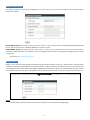
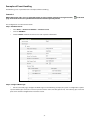
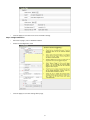
Network Camera NCB750 / NCB752 NDR720 / NDR722 NCR770 / NDR772 NDR721 User Manual 201504 A2 Table of Contents Important Notices 2 Get Started 2 1. Viewing Preparation 3 IP Finder 3 Discovering devices in Windows Network 4 ActiveX add-on Installation 5 2. Accessing the camera 7 Viewing the live video 7 The Live view page 9 3. Video & Audio 11 4. Network Configuration 20 5. Recording 25 Configuration of Event Handling 31 6. Event Management 31 Examples of Event Handling 38 7. System Options 41 8. Connectors & LED 45 9. Focus Assist Button (For NCB750&NCB752) 50 10. Desiccant Bag Replacement (For NCR770&NCR772) 51 11. Troubleshooting 52 Check firmware version 52 Upgrade device firmware 52 Recover device settings 54 Appendix A: Specifications of Fixed Network Camera 55 Appendix B: Specifications of IR Bullet Network Camera 57 Appendix C: Specifications of Indoor IR Dome Network Camera 59 1 Important Notices – Read Before Use This instruction manual is intended for administrators and users of the network camera, including instructions for using and managing the camera on your network. The use of video surveillance devices can be prohibited by laws that vary from country to country. It is the user’s responsibility to ensure that the operation of such devices is legal before installing this unit for surveillance purposes. Heed all warnings Before installing the IP Camera, please read and follow all the safety and operating instructions to avoid any damages caused by faulty assembly and installation. The user must adhere to all the warnings on the product and in this manual. Liability Every reasonable care has been taken in the preparation of this instruction manual. We cannot be held responsible for any technical or typographical errors and reserves the right to make alterations to the product and manuals without prior notice. We make no warranty of any kind with regard to the material contained within this manual, including, but not limited to, the implied warranties of merchantability and fitness for a particular purpose. The user should verify the relevant information is current and complete before placing orders. All products are sold subject to our terms and conditions of sale at the time of order acknowledgement. We shall not be liable nor responsible for the applications and resale of its products or bundled software with statements different from or beyond the specification/parameters stated by us. We are under no obligation to provide any further technical support service or product/software alteration beyond our representation. Trademarks All names used in this manual and products are probably registered trademarks of respective companies. CE/FCC Statement (EMC) This equipment has been tested and found to comply with the limits for a Class A digital device, pursuant to Part 15 of the FCC Rules which are designed to provide reasonable protection against such interference when the equipment is operated in a commercial environment. If the equipment is not installed and used in accordance with the instruction, it generates, uses, and can radiate radio frequency energy which may cause harmful interference to radio communications. Operation of this equipment in a residential area is likely to cause interference, in which case the user at his/her own expense will be required to take whatever measures may be required to correct the interference. Get Started This user manual is designed as a reference for the installation and manipulations of the unit including the camera’s features, functions, and detailed explanation of the menu tree. Please read this manual thoroughly and save it for future use before attempting to connect or operate the unit. 2 1. Viewing Preparation IP Finder IP Finder is a utility program that helps users locate the unit in the local area network which the computer is connected to. Please note that IP Finder works only on Microsoft Windows XP, Microsoft Windows Vista, and Microsoft Windows 7. Steps to get the utility program running are listed below. 1. 2. 3. 4. 5. Download IP Finder from MESSOA Website to the computer. Double click on IPFinder.exe in the IP Finder folder, and the IP Finder window should pop out. The window would list information of units in operation at present. Press FIND CAMERA to find more units. Locate and double-click one of the cameras in the list you want to configure the network settings. If you have multiple cameras connected to your local network, locate the MAC address on the camera to distinguish the target camera from others. Configure the following settings as needed. • NAME: Enter a descriptive name for the camera. • NETWORK SETTINGS: If you have a DHCP server on your network to assign IP addresses to network devices, enable the DHCP option. Otherwise, manually enter the IP ADDRESS, NET MASK and GATEWAY values. • USERNAME & PASSWORD: Manually setup preferred username and password. • SET: Whenever you make revision of camera settings, click “SET” to take effect. • SW DEFAULT: To perform the factory defaults excluding network settings of the selected camera. • HW DEFAULT: To perform the factory defaults of the selected camera. • RESET: To reboot the selected camera. Click Save to enable the settings and click Exit to exit the utility. 3 Discovering devices in Windows Network If the IP camera is installed in a network with DHCP and UPnP services, after obtaining an IP address from DHCP server, it can then be discovered in “Windows Network” of a client PC, see figure below. The reason for being automatically discovered is that the IP camera’s UPnP is default enabled (see Network → Network Connectivity). NOTE: The term “Windows Network” in given figure above is used in Windows Vista / 7. It can be referred to Windows XP “My Network Places” which possesses the same capability of discovering UPnP devices. Right-click on the device and select “Properties”, the pop-up window shows all the information related to the device, including the web access info. Use the web address to connect to the IP camera. Or simply double-click on the selected device, which gets immediately access to the camera webpage. To identify the camera from the listed devices in “Network”, utilize the UPnP name and the device’s MAC address. This MAC address can be found on the label. 4 ActiveX add-on Installation It is recommended to use Internet Explorer 8 or later as the primary browser to access the IP cameras website. The first-time access to the camera webpage will be prompted to install the ActiveX. To allow the installation, click “Install” on the message bar and follow the instructions to complete ActiveX installation. When the installation is completed, IE browser can display the live video of the IP camera as the below figure. NOTE: If, however, there is not any prompted message or ActiveX cannot be installed at all, it is needed to change the IE security level and settings. 5 <Example> Internet Explorer 9: Internet Options → Security → Custom level Ensure the “Download signed ActiveX controls” setting is either “Enable” or “Prompt” selected. 6 2. Accessing the camera Viewing the live video With the correct installation and IP settings, the camera device can be approached via network. There are three ways to view the live video from the camera, 1. Internet Explorer - Launch IE browser and input the IP address of the camera . 7 NOTE: IP cameras also support the other web browsers for viewing the live video such as Firefox, Google Chrome or Safari. 2. RTSP Player The live video of the camera can be played with RTSP players, such as VLC or QuickTime. The camera supports two simultaneous video streaming (see Video & Audio → Video Setting). To gain access to the camera for each video stream, the RTSP URL will be required. The default paths for the streams are “stream1”, “stream2” and “stream3”. The URL format should be input as below. Stream1: rtsp://Camera_IP/stream1 Stream2: rtsp://Camera_IP/stream2 Stream3: rtsp://Camera_IP/stream3 The example given below is the live video displayed with QuickTime player. 3. NVR / CMS Software IP cameras are ONVIF conformant products. Most of ONVIF conformant NVR / CMS software can retrieve the video from the cameras for both live view and recording. For more details about the support information and operation, please contact the software vendors. 8 The Live view page The following illustration shows the front page of IP camera website, Options within each item may differ slightly among different products (Here takes NDR721 as an example to illustrate the UI functions of the camera). Quick Index Video Stream Operations Live Window Live Video Window Quick Functional Buttons OSD 9 Snapshot: Press the button to capture an image photo Record: Press the button to start recording. Press again to stop it. Record Path/Set Path: set up a file path that video clips and snapshots can be stored. Full screen: Press the button to enter the full screen mode. Press ESC key to return. Manual trigger: Press the button as triggering an event. See Event Management for detail. Listen: Enable / Disable to receive video from camera. (NCR770, NCR772 do not support) Talk: Enable / Disable to send audio to camera. (Only for NCB750, NCB752) Digital Zoom: toggle the digital zoom function. Video Stream Operations Language selection for the WEB UI Select video stream for displaying on live video window Display the video in actual (configured) size or digital (scaled) Select the preferred streaming protocol on the client 10 3. Video & Audio This section describes how to configure the video streaming of the device and the related camera image configurations. Users with Administrator or Operator authority (see System → User Management) are able to do these configurations. Click on “Setup” of Quick Index to enter the Video & Audio page shown as below. The sub-settings under “Video & Audio” are: - Camera Setting - Video Setting - ROI (Region Of Interest) (NCB750, NCR770 and NDR720 Excluding) - Audio Setting (NCR770 and NCR772 Excluding) 11 Camera Setting Image Setting Brightness: the luminance of image view. Default value is 8; adjustable from 0 to 16. Contrast: the ratio of luminance of white to black. Default value is 8; adjustable from 0 to 16. Saturation: colorfulness of a color related to its own brightness. Default value is 8, adjustable from 0 to 16. Sharpness: refer to image acutance, which presents in the edges contrast of an image. Default value is 8, adjustable from 0 to 16. The 4 correlates are referring image appearance in terms of color/vision that is adjustable according to user preferences. Video Orientation: change the image orientation •• Mirror: rotate the image horizontally •• Flip: rotate the image vertically NOTE: These operations are usually applied when camera must be installed in an exceptional position. For the example of ceiling installation, camera must be installed upside-down. 12 Day/Night Day/Night Mode: Switch the video images for Day (plenty of light) or Night (Low light) scene. In default “Auto” mode, camera will switch to Day or Night vision according to the light intensity. The Day / Night modes contain 2 actions: switching IR Filter On / Off, and image hue Color / Mono. In day mode, the IR filter is switched in to avoid the image sensor from receiving the infrared, thus the true color image is provided. When camera enters night mode, IR filter is switched off to allow IR illuminations going into the sensor, thus increasing the images light level. The image color is switched to B/W (Mono mode). Nightmode Enhancement With this function enabled, the better night vision will be obtained. However, the number of FPS may drop depends on the actual environmental illuminations. Light Sensor Sensitivity The value reflects to adjust the sensitivity of Light Sensor. Night to Day Threshold The value reflects the timing switching from night to day. Day to Night Threshold The value reflects the timing switching from day to night. Switch Time The value reflects the delay time for both ways of day and night switch. Advanced Setting AC Frequency: Anti-flicker setting for environment with fluorescent light sources, image sensor needs to fit the frequency of light (power) source. For instance, the power frequency is 50Hz for most European countries, while 60Hz is typically for US. This setting is therefore regionally different. White Balance: The selections for different lightening condition, which is refereeing to color temperature. The default value is set to AUTO. Flickerless Mode: Flickering can also present in various exposure level. Set “Flickerless” Mode “On” to fix the maximum shutter speed (auto exposure control). Thus, the flickers can be eliminated. Exposure & Gain Mode: Select auto / manual Exposure & Gain control mode. The selection defines the controlling in a range of or fixed value, according to the following two items (Shutter Speed and Gain Value). The configurations will be limited at selected maximum rates when AUTO mode is on. Exposure Level: Adjust Exposure level for a target level of sensed brightness. Auto exposure function will adjust to exposure time to make the sense image brightness close to the target. Max. Shutter Speed: Also refer to the exposure time. Higher shutter speed is normally applied under strong light circumstance, so the image won’t be overexposure. Lower shutter speed, on the other hand keeps image luminance in low light environment. Max. Gain Value: Also refer to the amplification factor for the incoming light. Increasing the gain value provides a brighter image, but the noises may also be increased. WDR: Enable this function for image objects under backlight circumstances. NOTE The “Exposure Level”, “Shutter Speed”, “Gain Value” and “WDR” can be configured for daytime and nighttime. The configurations will be applied according to the current status of “Day/Night Mode“. 13 : represents the Day mode : represents the Night mode The setting items with the Day or Night mode symbol will be altered along with the setting of Day/Night mode. The examples are illustrated as below. Video Setting Video Stream This tab provides detailed stream configurations. These settings can affect resolution ratio, video size, quality. The maximum transmission performance can be expected under the condition of full network bandwidth. The camera supports up to 2 or 3 video streams (3 streams only for NDR721). Each stream can be configured with following items. 14 Resolution Ratio(Only for NDR721): 16:9 or 1.3M mode is selectable. The image ratio of Stream1 to Stream 3 will change at the same time based on a pre-defined table if user changes the ratio mode. Video Format: H.264, MPEG4 and MJPEG are available for the selection. The demand of bandwidth and storage requirement differs from the selection of video format. In the request of same video quality, H.264 contributes to less bandwidth and storage requirement, which can be more efficient than MPEG4 or MJPEG. Resolution: The resolution here describes an image size counted in width by height, e.g. 1280x1024, referring to pixel resolution. 15 The Codec combination table are listed in the following table. Mode ID NDR721 Stream Stream1 (Main Stream) Compression H.264 MPEG4 MJPEG 16:9 HD720, 800x450, mode 640x360, 320x180 1280x1024, 1024x768, Resolutions 1.3M 800x600, mode 640x480, 320x240, 60x120 30fps 25fps 30fps HD720 15fps 30fps 20fps 30fps 1280x1024 15fps X 30fps X 1024x768 30fps 15fps 30fps 800x600/ 800x450 30fps 640x480/ 640x360 30fps Mode ID Stream Compression Resolutions 1080P HD720 800x450 Stream2 (Sub Stream) H.264 MPEG4 MJPEG 800x450, 640x360, 320x180 800x600, 640x480, 320x240, 160x120 X 15fps X 15fps 10fps 15fps X 15fps 15fps 30fps NCB752, NDR722, NCR772 Stream1 (Main Stream) H.264 MPEG4 MPEG4 1080P, HD720, 800x450, 640x360, 320x180 30fps 10fps 30fps 25fps X 25fps 15fps X 15fps X 30fps X X 15fps X 30fps X 30fps 30fps Mode ID NCB750, NDR720, NCR770 Stream Stream1 (Main Stream) Compression H.264 MPEG4 MPEG4 1280x800, HD720, 800x450, Resolutions 640x360, 320x180 30fps X 30fps 1080P/ HD720 X 30fps X X 15fps X 800x450 30fps 16 Stream3 (Sub Stream) H.264 MPEG4 MJPEG 800x450, 640x360, 320x180 800x600, 640x480, 320x240, 160x120 X 15fps X 15fps 10fps 15fps X 15fps 15fps 30fps Stream2 (Sub Stream) H.264 MPEG4 MJPEG 800x450, 640x360, 320x180 X 15fps 30fps X 15fps 30fps 30fps Stream2 (Sub Stream) H.264 800x450, 640x360, 320x180 30fps 25fps 30fps 15fps X 15fps 15fps 30fps Enable ROI(NCB750, NCR770 and NDR720 Excluding): Once the ROI function enabled, relative ROI area could be setup under the “ROI” page. Frame Rate: It represents the number of frames that are displayed per second. The higher the frame rate is the better/ smoother the video stream can be obtained. However, it would be the tradeoffs for the higher network bandwidth and storage requirement. Intra Frame Period: This is applied only in MPEG4 / H.264 which the video stream is composed of I-frames (full image information) and P-frames (motion-compensated difference information). This setting configures the time period between 2 I-frames. The shorter period means the higher frequency of I-frame. Video can then be well handled whereas the bit rate may increase. Video Quality: There are four types of bit rate controls for video quality adjustment, Constant Bit Rate (CBR), Variable Bit Rate (VBR), Enhanced Constant Bit Rate (ECBR) and Enhanced Variable Bit Rate (EVBR). For CBR, the video bit rate is between low to high bandwidth based on different resolutions. The user can set the desired bit rate to match the limitation of bandwidth. For VBR, the user should choose the quality level to set the video quality rather than bit rate. The quality level separates into standard, good and excellent. For ECBR, the video bit rate is based on normal CBR mode. However, the target bit rate can be increased to max target bit rate while lots of motion in video. The max target bit rate will keep a predefined time period and then back to normal CBR bit rate. For EVBR, the video bit rate is based on normal VBR mode. However, the bit rate can be limited to the max bit rate while lots of motion in video NOTE: CBR, ECBR, and EVBR are not applicable in MJPEG video mode. Video Overlay The camera supports OSD (On Screen Display) which means stamping text information on the video image. The options of the date/time string or/and a line of text message (e.g. camera name or location) are available for displaying on the images. Also, the transparent percentage of the OSD background could be adjustable. For the user define text OSD, it supports ASCII and UTF-8. ASCII text includes only limited standard characters, and UTF-8 fits for those applications which need OSD with multiple language OSD support. UTF-8 works on IE8 or above, chrome, and Firefox. 17 Privacy Mask Privacy Mask can block out the specific areas from view. The blocked areas will not be seen in both live view and recorded video clips and the total of 8 profiles can be created to the list. To create Privacy Mask, simply input Privacy Mask Name and click “Add New” button and then apply it to complete the addition. ROI(NCB750, NCR770 and NDR720 Excluding) The checkbox of “Enable ROI” under Video Setting page should be clicked before active the function of ROI. Region of interest that users could determine the region what would be monitored. To drag any corner of red rectangle to resize the window and the modified video resolution will be shown on right side in red. 18 Audio Setting (NCR770 and NCR772 Excluding) Check the “Enable Audio” checkbox to enable the video streaming with audio. The audio encoding supports G.711 ulaw and AAC. For Audio Input Setting, the input source can only be Internal Microphone. 19 4. Network Configuration The IP Camera acts as one of the network devices. It allows user to configure the network functionalities based on applications. This section will describe the network configurations. The subdirectories in “Network” are: - Network Type - Network Connectivity - Quality Service - Access Port - Access IP Filter Network Type Network Type There are 3 ways to configure address for the IP camera device, including DHCP, Static IP and PPPoE. Enable DHCP Service: The default setting is DHCP, which camera will be automatically given an IP address (IPv4/IPv6) in a network with DHCP server. Use Static IP: Camera may also be manually assigned with a static IP address (IPv4/IPv6). Subnet mask, Gateway and DNS server(s) will also need to be specified for certain network function properly executed. Enable PPPoE Service: This service is usually provided by an ISP (Internet Service Provider). IP Camera can establish a dial-up connection to the ISP and then get connected to Internet. (Only IPv4) 20 NOTE1: To connect camera with IPv6 address, please note that this only works if the network environment and hardware equipment support IPv6. The browser should be Microsoft® Internet Explorer 6.5, Mozilla Firefox 3.0 or above. NOTE2: (Link with IPv6 address as following steps) 1. Go to Setup -> System -> System Information page (under IPv4) to know the IPv6 address 2. Open web browser and input the IPv6 address in the address bar. 3. The format should be: http://[2014:db8:0:1:2e0:d8ff:fe0c:adef]/ 4. Press Enter key to open the Live View page of camera. For example 21 Network Connectivity This page provides the connectivity configuration, so that IP camera can be accessed without necessarily providing the numerical IP address. Enable UPnP Service: with UPnP enabled, IP camera device can be easily discovered in Windows Network (My Network Places). See “Discover devices in Windows Network” in previous section. Enable DDNS Service: By registering this sort of service, camera can be assigned and accessed over Internet with a hostname instead of IP address. To enable the services, visiting the website of the service provider and registering an account are required. Dyndns.org: http://www.dyndns.com/ Quality Service Quality Service provides network traffic management to guarantee the quality of services in higher priority, especially when network is insufficient. DSCP (Different Service Code Point) is a 6-bit IP header which defines the service level of the packet. According to the DSCP value, routers with PHB (Per-Hop Behavior) will define a specific class of traffic for the packet, in terms of bandwidth, latency, or loss rate, etc. Enable QoS and set DSCP value for the service to ensure its quality to be maintained. NOTE: To make the QoS function work, all the switches and routers in the network must support QoS. 22 Access Port This page provides the ports configuration for requesting the services from the camera device. These services include Web Page access, HTTP and RTSP streaming services. HTTP port / HTTPS port: By default, the HTTP and HTTPs ports are set to 80 and 443 respectively. They can also be assigned to another port number between 1025 and 65535. The HTTP port is basically provided for device’s webpage access. When the video format is set to MJPEG, user is able to retrieve the live video via HTTP URL, e.g. Http://<ip_address>/operator/get_video.cgi?channel=[1, 2] , where channel is to specify stream1 or stream2 RTSP port: RTSP (Real-Time Streaming Protocol) is used to control the live media streaming. This port is provided to request the streaming service. By default, the port number is set to 554. It can also be assigned to another port number between 1025 and 65535. Multicast: Multicast is a streaming method with bandwidth conserving technology. By delivering a single video stream to multiple network clients, the bandwidth utilization can be reduced. Select the Always multicast option to enable multicast for stream 1 ~ 2. Multicast Group Address – Set the IP address for multicast streaming. The Multicast IP address must be in the range from 224.0.1.0 to 239.255.255.255. Multicast Ports – Set the port for multicast streaming. Multicast TTL – The multicast Time-To-Live (TTL) gives the range of routers that multicast traffic can pass through in the networks. NOTE: The multicast stream can be triggered by a network client (e.g. choosing “Multicast” from the live view page) whereas “Always Multicast” option is not enabled. This mechanism is known as “Multicast On Demand”. In this mode, multicast stream starts when one or more clients request. It stops automatically when the last client leaves the multicast group. “Always Multicast”, on the other hand, starts or stops multicast stream by enabling/disabling this function. It doesn’t matter whether there is client request or not. 23 Access IP Filter This setting also provides a basic security by filtering the accesses from other hosts. Enable this function and choose “Allow / Deny” of the listed IP addresses. Up to 15 IP address can be added in the list for IPv4 and IPv6. 24 5. Recording This section provides the recording configuration on the camera. Unlike the recording function (Quick Functional Button) on the live view page, video can also be recorded to the storage attached to the local network storage (Samba) according to a time based schedule. The subdirectories in the “Recording” category are: - Recording Plan - SD Storage (For NCB750, NCB752 and NDR721) - SD File List (For NCB750, NCB752 and NDR721) - Samba Recording Plan Recording Plan List It lists the created/scheduled recording plan(s). The details of a recoding plan include: Plan Name: Identifier of the recording plan Status: Enable or Disable the recording plan Mon ~ Sun: Displays the hours in days of a week that recording is effective Src. (Source): The video source selected to be recorded Dest. (Destination): The stored path for the recording file Remove: Click to delete this recording plan. 25 Add / Edit Recording Plan Plan Name: Identifier of the recording plan Video Source: The selection of the video source to be recorded. Options: Stream1 / Stream 2 / Stream 3 for NDR721 and Stream1 / Stream 2 for others. Maximum File Size: This option defines the maximum file size of each video clip. Destination: The stored path for the recording file Select All: 24 hrs/ 7days (Mon-Sun) continuous recording Scheduled Pattern: User-defined time frame Network fail (Only for NDR721) The user could checked the check box to enable recording to SD card upon the condition of network failure 26 SD Storage (For NCB750, NCB752 and NDR721) This page shows the SD card information when it is attached to the IP camera. Normally, inserting the micro SD card will be done before entering this page and obtain the card information as below. However, if it is the other way around, click SD storage tab to refresh it. SD Card Status: •• Syncing: Display when the card database is in the process of synchronization •• Ready: Display when the micro SD card has been detected successfully is in a ready state •• Detached: Display when there is no micro SD card detected •• Recording: The micro SD card is being recording recorded •• Remove button: Remove the micro SD card •• Mount button: Mount the micro SD card Used (%): Display the used space in percentage. Click Refresh button to obtain the up-to-dated value Disk Format: Click Format button to format the micro SD card NOTE: 1. 2. It is recommended to insert the micro SD card before powering up the system. This is to ensure that the attached device is properly detected in the initial stage. When the card storage is full, the system will automatically launch overwrite process from the earliest recording files. 27 SD File List (For NCB750, NCB752 and NDR721) This page provides the search of records. The SD storage may contain both “triggered-by-schedule” recordings and “triggered-by-events” snapshot / video. There are search conditions used to narrow down the search results. The latest 10 Records The most recent 10 records are listed in this table. Each record name is a link to view this video or image. Following the “Record Name”, each record is listed with its “Trigger Type” and “Record Size” details 28 Searching the Records The SD storage would keep massive records after the “recording plan” and/or “event handling” (see Event Management) has been launched. The search criteria are provided to look for particular records in the SD card. Example: Trigger Type – Schedule Recording There are 3 categories of search criteria: 1. Trigger Type: It includes Motion Detection, Digital Input, Manual Trigger, Network Fail, Audio Detection and Periodically as the type of “triggered-by-events” and Schedule Recording as the type of “triggered-by-schedule”. 2. Trigger Time: Input Date / Time duration that recording was created. 3. File Type: Select the file type that is either video clips (.avi) or pictures (.jpeg) or both. NOTE: The search criteria can be multiple selected for each searching. For instance, the search result can be the combination of Network Fail and Digital Input. 29 Samba This page allows user to configure the file storage via Samba. To begin with it, click Enable Samba and then input the related information. NOTE: Samba can only support mounting a shared folder located in the root directory. For example, to mount a folder called “Shared” can be input the path as below. \\<IP>\Shared 30 6. Event Management Event management describes the handling of events with the corresponding actions. A common case can be exampled is storing a captured image to a local storage (Actions), when there is a Motion Event (Trigger Condition). This chapter gives the configurations of Triggers (what to detect?) and Actions (“what to send” and “where to send”). A time based schedule can also be applied. Configuration of Event Handling There are several subdirectories in the “Event” category. These configuration groups are correlated. A completed event setting may need to configure each part in sequence. - Event Server & Media - Motion Configuration - Audio Detection (For NCB752, NDR721 and NDR722) - DI/DO Setting (For NCB750, NCB752 and NDR721) - Tamper Detection (For NDR722, NCB752 and NCR772) - Event List Event Server & Media The “Event Server” is the configuration of “where to send”, e.g. FTP server, while Media is the sending file type. The combination of file type and the remote servers will then be applied as an event action. Event Server List Click on “Add New” button to add the remote servers. These are email recipients and FTP server. 31 Server Name: Identifier of the event server Server Type Email: Send the media file via email when an event is triggered. •• Mail Server Address: Enter a host name or IP address of the email server. •• User Name: Enter the user name of the email account. •• Password: Enter the password of the email account. •• Server Port Number: Enter the server port of the mail server. The default is 25. •• Sender’s E-mail Address: Enter the email address of the sender •• Mail Subject Prefix: Enter the subject description for the mail. •• SSL/TLS : Select None/SSL/TLS for secure the mail transmission •• Receiver Table: Enter the recipients’ email address. The mail can be sent to up to 5 recipients. FTP: Send the media file to a FTP server when an event is triggered. •• FTP Server address: Enter the FTP server’s address. •• User Name: Enter the user name of the FTP login account. •• Password: Enter the user name of the FTP login password. •• Server Port Number: Enter the server port of the FTP server. The default is 21. •• Upload Path: Enter the file path that files will be sent to. Media Type There are 2 types of media (file) available, snapshot (.jpg image) and video clip (.avi). Video Source: Select the video source to be captured Pre-alarm / Post-alarm image(s): Enter the numbers of images that will be captured before and after trigger is activated. Pre-alarm / Post-alarm record: Enter the numbers of seconds that video will be recorded before and after trigger is activated. Maximum file size: Define the maximum file size that a video clip is generated. 32 Motion Configuration There are three MD (Motion Detection) areas can be enabled. Each MD can be individually enabled/disabled, defined the covering range and trigger sensitivity. To enable and verified the MD, follow the steps provided below. 1. Check the box to enable the motion area 2. Drag and drop to move the motion window 3. Hold and drag any corner of the rectangle to resize the window. 4. By dragging the pin of the slider bars, adjust the detection “Sensitivity” and “Object Size” of the rectangle covered area. NOTE: By name implying, the “Sensitivity” setting means the sensitivity level to the motion detection; the higher value given makes the motion window more sensitive to the moving object. “Object Size” stands for the percentage threshold of moving object size verse motion window size. For example, the “Object Size” set as 50 that means the “size of detected moving object” must larger than 50% of the motion window to trigger the motion event. 5. 6. The status chart shows the motion activities. When the motion vector exceeds a threshold (the Object Size), the motion trigger is activated. The index number of “Show in chart” reflects the number of Motion Area. To enable other motion area, repeat above steps. 7. Click on “Apply” button to save the settings. 33 Audio Detection (For NCB752, NDR721 and NDR722) Checked the box of Enable Audio Detection, users may enable audio detection function to detect the monitoring area whether any abnormal sound over the threshold existed. This could be an event source to trigger event notification and alarms. DI/DO Setting (For NCB750, NCB752 and NDR721) The DI/DO setting provides the function of Digital I/O’s trigger condition configuration and current status information. The trigger condition can be configured while current status is detected by the IP camera system. Digital input (DI) can be configured as Open Trigger, Close Trigger, or disable. When its current status fits the trigger condition, the trigger is activated. Digital output (DO), can be one of the responding actions, when event it triggered, the DO will change output from Open to 12VDC when Trigger condition configured as 12VDC. The DI could also be configured as camera Day/Night mode switch input to synchronize with Day/Night signal output from an external illuminator or an external light sensor. And, DO could also output camera Day/Night status while configured as Day/Night Output, which could used to control an auxiliary illuminator. 34 Tamper Detection (For NCB750, NCB752 and NDR721) With tamper detection, the camera is capable to detect tampering and could be event source to trigger event notification and alarms. 35 Event List List a summary of configured events. That is the selection of trigger condition(s) and the corresponding actions, as well as the scheduling. To begin with it, click on “Add New” button to extend for the detailed configurations. Event Name: Enter an event name, e.g. Motion Detection, to identify this configured event. Select All: 24 hrs/ 7days (Mon-Sun) continuous recording Scheduled Pattern: User-defined time frame 36 Triggered by: This describes the selection of trigger conditions which include: •• Motion Detection: Select the motion detection area(s) used for trigger condition. To enable and configure the motion detection areas, go to Motion Configuration. •• Digital Input: Enable the system to detect the DI (Digital Input) status as a trigger condition. For more details about the DI setting, go to DI/DO Setting if the mode support. •• Manual Trigger: Enable the system to detect the user input action (press the alarm button, on the live view page). •• Network Fail: Enable the system to detect the network connection status. •• Periodically: Enable the system to perform the set Action periodically. •• Tamper Detection: Enable the event to detect the tampering event. •• Audio Detection: Enable the event to detect the audio event. Action: The selection of responding actions •• Digital output: Check the box to enable the digital output as a responding action. For detailed configurations, go to DI/DO Setting. •• Upload files to a server: There are two drag-down selections, Event Server and Media Type. The Event Server indicates the file destination such as local network storage Samba, and the file type includes snapshot image and video clip. For the snapshot / video clip configurations, go to Event Server & Media. NOTE The dependency of Event Server and Media Type is described as below. ‐ When Event Server is either Samba or SD card, the selection of Media Type will be either Image or Video ‐ When Event Server is either Mail or FTP, the selection of Media Type will only be image 37 Examples of Event Handling The following cases are provided as the examples of Event Handling. Scenario 1 While viewing live video, user can manually trigger an event anytime simply by pressing the button, page. It will send email to the specified email accounts with the captured pictures. on the web The configurations are illustrated as below: Step 1: Add Event Server •• Go to Event → Event Server & Media → Event Server List •• Click on “Add New” •• Choose “Email” and fill in the email server and recipients’ information. Step 2: Configure Media Type •• On the same web page, configure the Media Type. For the following example, the system is configured to capture 1 picture before (pre-alarm) the event and 2 pictures for the event and after (post-alarm). For video clip, pre-alarm and post-alarm could be configured for event video record. 38 •• Click on “Apply” to save the email server and media settings. Step 3: Configure Event List •• On Event List page, click on “Add New” button. •• Enable and configure this event a b c d e f •• Click on “Apply” to save the settings of this page. 39 Scenario 2 A user is to define the motion detection area(s) in the camera view. When someone goes across these areas, the camera is aware of the trigger activated and starts generating video clips to the SD card if the camera support local storage. Meanwhile, an illuminator device attached to the camera will be lighted up. This detection should be activated from 22:00 to 08:00 every day. The configurations are illustrated as below: Suppose that the required media type is previously configured. That is the 7 seconds video clip configured in Scenario 1. Step 1: Define the motion area •• Go to Motion Configuration page, and define the MD area. Step 2: Configure DI/DO setting •• Go to DI/DO Setting page to set up the “Initial Status” of the digital output. NOTE The “Initial Status” is the normal state (no event triggered) of the DO pins. In the case, suppose that the connected illuminator can be driven by DC12V. The initial status should then be set “Open”. When a motion event is detected, camera changes the output status to “12VDC”. The illuminator is then lighted up. Step 3: Configure Event List •• Go to Event List page. Click on “Add New” button. •• Enable and configure this event •• Click on “Apply” button to save the settings of this page. 40 7. System Options System Options provide users to obtain and configure the system settings of the IP camera system. It contains the page of System Information, Date and Time, User Management, Maintenance and Log Service. The details about each subcategory will be described as below. System Information The page gives the general information of the IP camera system. In System Status, the Model ID, Firmware Version and MAC Address are listed. The Camera Name and Location fields are revisable to identify a unit among multiple cameras installed. The IP address information of this IP camera is listed in Network Status. The RTSP Status field shows the video stream(s) being requested by the listed client(s). 41 Date and Time This section describes the date/time adjustment for the IP camera system. The ways to adjust the IP camera’s date/time can be Synchronize with NTP Server, Synchronize with PC or Set Manually. Current Date & Time Display current system date/time of the IP camera. The date format can be changed from the drop-down list under Configure Date & Time. Configure Date & Time Keep Current Date & Time: The option of keeping current date and time, not to be adjusted. Synchronize with NTP Server: Automatic date/time adjustment. The IP Camera must be able to access to the given NTP server. NOTE: To apply “synchronize with NTP Server”, a Time Zone must be selected for referencing to the local time. Synchronize with PC: The PC linked to the web page of the IP camera can also be a date/time synchronizer. However, if the PC is linked from a time zone which is different from the one where camera is installed, the web page will pop up a warning message for time zone difference. Set Manually: Manually adjust the date / time. Date & Time Display Format: The system date can be displayed in the format of DD/MM/YYYY, MM/DD/YYYY or YYYY/MM/ DD. The system time can be displayed in the format of 12H or 24H Time Zone: Select an appropriate time zone for local where IP camera is installed. The automatic adjustments will be applied based on the selected time zone. Click the “Daylight Saving Time Enable Automatically” checkbox to enable the daylight saving function and user could select the day light saving start time and end time based on the DST rule where camera installed. 42 User Management By default, the access to the camera is not user authenticated. For security, the IP camera should be restricted only authenticated accounts to access. It is able to enable/disable user accounts, as well as to manage the added users in this page. Initially, there is a default account, Admin in the “User List”. To enable this account, click on “Enable Authentication” and then apply. To edit password for the default account, click “Edit” to enter the configuration window. To create a new account, click “Create User” button. Enter Account / Password for this account with the group type on the “Create account” window. The user account with “Administrator” authentication can do all the configurations. “Operator” has the same rights as Administrator, except for User Management. “Viewer” is allowed only the access to live view page. Up to 8 user accounts can be added in the User List. 43 Maintenance This page provides tools for camera system maintenances. Reboot: Restart the camera system Restore to Factory Default: Restore camera factory default settings. The network setting can be kept by checking the “Except Network Type” checkbox. Backup Configurations: The system settings can be backed up and exported to a file. The file can be applied to upload the previous user settings to the camera, or other cameras. NOTE: The backup file can be applied to other IP cameras, so users won’t need to configure each device. It is recommended to switch the IP setting to DHCP mode before exporting the backup file. Otherwise, all IP cameras will have the same IP address. Firmware Upgrade: There may be new released firmware for features update or issues fixed. To upgrade the firmware for the system, retrieve the firmware image file, import to the system and then do the upgrade process. LOG service The system operations and / or process will be recorded in the log system. The link provides the review of these records. System Log: It contains records of system changes such as login failed or link on/off. Event Log: It records the log message of triggered event, for instance, motion detection is asserted. Parameter List: It lists all the system parameters with the current value. 44 8. Connectors & LED NCB750 & NCB752 Front and Back Panels I/O connectors – Pin definitions Pin Signals Function 1 RX-IN Digital Input 2 GND Ground 3 DO-OUT Digital Out Schematic diagram of Digital I/O 45 LED Indicators There are 2 type of LED indicators; RJ45 LEDs (back panel) and System LED (front, bicolor). These LEDs can help to recognize the current device status. RJ45 LEDs for Network Status: 10 Link / Traffic 100 Link / Traffic LED1 (Green) Steady ON / Flashing Steady ON / Flashing LED2 (Amber) OFF Steady ON Bicolor LED indicator for Power & System Status: Green Steady ON with Amber LED 3 Flashing then ON with Green LED Steady ON with Green LED Flashing per second with Red LED Steady ON with Red LED Power On / System Reboot Initial Process Ready Normal Operation Firmware Upgrade Internal (Hardware) Failure NCR770 & NCR772 Cable connectors LED Indicators There are 2 type of LED indicators; RJ45 LEDs (back panel) and System LED (front, bicolor). These LEDs can help to recognize the current device status. RJ45 LEDs for Network Status: 10 Link / Traffic 100 Link / Traffic LED1 (Green) Steady ON / Flashing Steady ON / Flashing 46 LED2 (Amber) OFF / OFF Steady ON / Steady ON NDR720 & NDR722 Physical appearance and connectors Reset button Mic Light Sensor System LED Indicator LED Indicators There are 2 type of LED indicators; RJ45 LEDs (back panel) and System LED (front, bicolor). These LEDs can help to recognize the current device status. RJ45 LEDs for Network Status: 10 Link / Traffic 100 Link / Traffic LED1 (Green) Steady ON / Flashing Steady ON / Flashing LED2 (Amber) OFF Steady ON Bicolor LED indicator for Power & System Status: Green Steady ON with Amber LED 3 Flashing then ON with Green LED Steady ON with Green LED Flashing per second with Red LED Steady ON with Red LED Power On / System Reboot Initial Process Ready Normal Operation Firmware Upgrade Internal (Hardware) Failure 47 NDR721 Connectors Schematic diagram of Digital I/O 48 LED Indicators Bicolor LED indicator for Power & System Status: LED Steady ON with Amber LED 3 Flashing then ON with Green LED Steady ON with Green LED Flashing per second with Red LED Steady ON with Red LED Power On / System Reboot Initial Process Ready Normal Operation Firmware Upgrade Internal (Hardware) Failure 49 9. Focus Assist Button (For NCB750&NCB752) Focus Assist Button allows users to adjust the camera focus with precision by a simple click. [Steps of Process] Step 1: "Press" Focus Assist Button ●● Rotate the lens focus clockwise or anticlockwise to either end (N or ∞) ●● Press and hold the button for 3 seconds until LED indicator flashes from Green light to Amber light. Flashing Green Steady Amber Step 2: Adjust Focus ●● Keep the camera pointing to the same scene during the tuning process ●● Start tuning the focus in order to turn the LED Green. ●● If LED displays Red light, it indicates the opposite turning direction. Step 3: Get the Best Focus Value ●● When camera gets correct focus, the LED will become Green flashing. ●● Remain the camera’s pointing direction until the LED becomes steady Green 50 10. Desiccant Bag Replacement (For NCR770&NCR772) The Camera comes with a desiccant bag placed inside. It is not necessary to replace it until the rear cover of the camera has been opened for some reasons. The SOP is described below for users to complete the replacement. Step 1: Unscrew the rear cover of the camera Step 2: Carefully open the rear cover and find the location as the red box shown below for installation. Desiccant bag Step 3: Close and screw the rear cover firmly. (M3 screw force: 12kgf / cm2) Note: Please ensure that cable management is completed prior to putting back the rear cover. 51 11. Troubleshooting Check firmware version Firmware version may imply the functionalities’ updates or availability in the camera system. Therefore, in the first step of troubleshooting and then reporting, it helps to locate the found issues. Newer version firmware may have these issues corrected. The version code can be found in Setup -> System -> System Information, see figure below. Upgrade device firmware Firmware upgrade process should be done via the web configuration: Setup -> System -> Maintenance -> Firmware Upgrade. Before the process, read the instructions and release notes coming with each new released version. [Read Before Upgrade] 1. The latest firmware image is available on our official website. 2. Make sure all other client connections are disconnected and current jobs such as recording are required to terminate. 3. During the upgrading period, DO NOT disconnect the power of the camera. Otherwise the unit might be damaged. [Steps of Firmware Upgrade] 1. Go to firmware upgrade page on the web. Figure 1 2. Click “Firmware” button to load the firmware image. Figure 1 3. Click “Upgrade” to begin (the upgrade progress bar will pop up). Figure 2 4. Once it is done, the system will reboot automatically. 5. Go back to firmware upgrade page and confirm if the “current version” is up-to-dated. Figure 3 52 Figure 1 Figure 2 Figure 3 53 Recover device settings In some cases, camera system does not respond to any operation. A certain recovering processes would help to get the unit back to initial status, so that it can resume operable / configurable. This will be the operations on the “Reset Button”. Before executing hardware reset, please make sure the system booting process is completed. Normally, it takes 30 seconds to complete the process. 1. Restart / Reboot the device Press and release the Reset Button within 5 second, the system will be restarted (the LED Indicator will be steady amber during rebooting process). Upon successful reboot, the LED will be steady green during normal operation. 2. Reset account/password to factory default Press and hold the Reset Button over 5 seconds, the LED will change from steady green to flashing green. During LED flashing as green, then release reset button, ONLY account/password will be reset as factory default, which is Admin/Admin. Please notice that, all configured accounts/passwords will be cleared and only the default one will be reserved. 3. Reset to factory default settings Press and hold the Reset button over 10 seconds, the LED will change as flashing red. During LED flashing as green, then release the reset button, ALL settings will be reset as factory default. The system will enter the restoring process automatically and complete it in 30 seconds after reset button released The following chart illustrates the reset behaviors. 54 Appendix A: Specifications of Fixed Network Camera Video Model Type Sensor Type Active Pixels Compression Streaming Resolution Max. Frame Rate Day/Night Day/Night Mode Shutter Time Minimum Illumination NCB750 1/4" 1M progress scan CMOS sensor 1280 x 800 (HxV) H.264 / MPEG4 / Motion JPEG Dual simultaneous streams (WXGA)1280x 800, 1280x 720, 800x450, 640x360, 320x180 Megapixel (1280x 800) at 30 fps (NTSC/PAL) Mechanical (ICR) D/N Control Auto/ Day/ Night Range from 1/960s to 1/30s selectable (60Hz); Range from 1/1000s to 1/25s selectable (50Hz) Color (Shutter Speed: 1/30 sec): 0.4 Lux @10IRE; 0.8 Lux @50IRE NCB752 1/2.7” 2MP progressive scan CMOS sensor 1920 x 1080 (HxV) 1920x1080, 1280x720, 800x450, 640x360, 320x180 Full HD (1920x1080) at 30/25fps (NTSC/PAL) Range from 1/7s to 1/30,000s Color (Shutter Speed: 1/30sec): 0.08 Lux@10IRE; 0.4 Lux @50IRE B/W (Shutter speed: 1/30sec): 0.02 Lux @10IRE; 0.1 Lux @50IRE Video Output B/W (Shutter speed: 30 sec): 0.16 Lux @10IRE; 0.32 Lux @50IRE NTSC: 720 X 480 @30fps; PAL: 720 X 576 @25fps Bit Rate Control Simultaneous stream bit rate control: CBR/VBR Simultaneous stream bit rate control: CBR/VBR/ECBR/EVBR Fixed Lens, f=4mm, F1.5 (Mega pixel lens) - View Angle H: 53.1°/ V: 33.7° - IRIS Control Lens Mount Audio Audio Communication Compression Audio In/Out Image Enhancement Yes CS Mount DC IRIS CS Mount Lens Type, Focal Length, F-number Two-Way Mono Audio, Full-Duplex G.711 μ‐Law , PCM, 8kHz Built -in microphone, External microphone and speaker AWB, AES, AGC; IRIS Mode: Off/ Auto; Flickerless Mode: On/ Off; Image Settings Exposure & Gain Mode: Auto/ Manual; White Balance: Auto/ Fixed; Sharpness, Saturation, Brightness, Contrast: 17 level sensitivity; Exposure Level: 15 level sensitivity; Digital WDR Yes; 8 level sensitivity DNR Auto/On/Off Privacy Zone Yes; customized threshold privacy zone (up to 8) Image Orientation Mirror, Flip Frequency Control 50Hz, 60Hz Date & Time Stamp Yes Test Overlay Yes Intelligent Video & Event Management Motion Detection Up to 3 customized threshold detection windows, 101 detected object size or level sensitivity Ethernet Detection Network Fail detection Others Snapshot, digital Zoom, Optimized i-frame setting Motion detection, External alarm, Manual Motion/Tamper/Audio detection, External alarm, Events Manual Trigger, Network Fail, Periodically Trigger. Trigger, Network Fail, Periodically Trigger. File upload via FTP, SMTP, SAMBA and SD Card; Notification via FTP, email and External output Event Actions activation; Video and audio recording to SD Card or SAMBA Alarm / Motion / Schedule/ Un-interrupt recording Store Category Stores video clips and snapshots 55 Local Storage Memory Card Slot Memory Card Overwrite Network Protocol Ethernet PoE ONVIF Browser Security I/O & Controls Power Power LED Indicator Alarm In/Out Network Audio In/Out Analog Video Reset Bicolor LED Focus Assist Button Power Power Requirement Power Consumption (Max.) Mechanical Dimensions(WxDxH) Weight Battery Backed-up Real-time Clock Environmental Operating Temperature Operating Humidity Storage Temperature Regulatory Approvals Ordering Information Accessories Micro SD / Micro SDHC Card up to 32 GB Yes IPv4, IPv6, HTTP, HTTPS, SMTP, FTP, DHCP, NTP, TCP/IP, UPnP, RTSP/RTP/RTCP, DNS, DDNS, PPPoE, IGMP, QoS, Bonjour, Samba, Multicast. 10Base-T/100Base-TX Ethernet connection for LAN / WAN, RJ-45 IEEE 802.3af Yes IE Browser 8.0 or 9.0 IE Browser 8.0 or above, Chrome, Firefox, Safari Three-level access with password protection DC 12V: DC Jack (2.0mm) AC 24V: Screwless Terminal block Yes Terminal Block 1 in / 1 out RJ-45 with LEDs (Network indicator) 3.5mm Phone Jack 1 in / 1 out for external microphone/speaker; Built-in Microphone BNC X1, 1.0Vp-p, 75Ω Within 1 sec for rebooting system; more than 10 sec until red LED starts to flash for loading default Focus & Power & System Status YES (fine tune focus according to LED indicator) DC 12V & AC 24V ± 10% / PoE(IEEE 802.3af ) 8W 66 x 65.5 x 55 mm (2.60" x 2.58" x 2.17") 270g (0.60 lb) w/o lens Yes; Internal RTC 0ºC ~ 50ºC (32ºF ~ 122ºF) 20~ 90% RH -10°C ~ 55°C ( 14°F ~ 131°F ) CE, FCC, RoHS Wall mount with free pack-in camera stand, Power Adapter Note: 1. Memory card not included. 2. No memory card clot & local storage function for Argentina and Ecuador 3. Product specifications and pictures are subject to change without notice. 56 Wall Mount Stand Appendix B: Specifications of IR Bullet Network Camera Video Model Type Sensor Type Active Pixels Compression Streaming Resolution Max. Frame Rate Day/Night Day/Night Mode Shutter Time Minimum Illumination NCR770 1/4" 1M progress scan CMOS sensor 1280 x 800 (HxV) H.264 / MPEG4 / Motion JPEG Dual simultaneous streams (WXGA)1280x 800, 1280x 720, 800x450, 640x360, 320x180 Megapixel (1280x 800) at 30 fps (NTSC/PAL) Mechanical (ICR) D/N Control Auto/ Day/ Night Range from 1/960s to 1/30s selectable (60Hz); Range from 1/1000s to 1/25s selectable (50Hz) IR LED Off (shutter speed: 1/30 sec): 0.6 Lux @10IRE; 1.2 Lux @50IRE NCR772 1/2.7” 2MP progressive scan CMOS sensor 1920 x 1080 (HxV) 1920x1080, 1280x720, 800x450, 640x360, 320x180 Full HD (1920x1080) at 30/25fps (NTSC/PAL) Range from 1/7s to 1/30,000s IR LED Off (shutter speed: 1/30 sec): 0.2 lux @10IRE; 0.8 lux @50IRE; IR LED On: 0 lux Video Output IR LED On: 0 lux NTSC: 720 X 480 @30fps; PAL: 720 X 576 @25fps Bit Rate Control Simultaneous stream bit rate control: CBR/VBR Simultaneous stream bit rate control: CBR/VBR/ECBR/EVBR Lens Type, Focal Length, F-number Built-in Fixed Lens, f=4.2mm, F1.8 (Mega pixel lens) Built-in Fixed Lens, f=4mm, F1.8 (Mega pixel lens) View Angle H: 49.8°/ V: 39° H: 84.8°/ V: 45.2° IR LEDs LED Quantity 12 pcs (850nm) IR Distance 10 meters (33 ft.) IR turn on status Under 10 Lux by auto control (light sensor), threshold adjustable in UI LED Life More than 10,000 hours (50ºC) Image Enhancement AWB, AES, AGC; Flickerless Mode: On/ Off; Exposure & Gain Mode: Auto/ Manual; Image Settings White Balance: Auto/ Fixed; Sharpness, Saturation, Brightness, Contrast: 17 level sensitivity; Exposure Level: 15 level sensitivity; Digital WDR Yes; 8 level sensitivity DNR Auto/On/Off Privacy Zone Yes; customized threshold privacy zone (up to 8) Image Orientation Mirror, Flip Frequency Control 50Hz, 60Hz Date & Time Stamp Yes Test Overlay Yes Intelligent Video & Event Management Motion Detection Up to 3 customized threshold detection windows, 101 detected object size or level sensitivity Ethernet Detection Network Fail detection Others Snapshot, digital Zoom, Optimized i-frame setting Motion detection, Manual Trigger, Network Fail, Motion/Tamper detection, Manual Trigger, Events Network Fail, Periodically Trigger. Periodically Trigger. File upload via FTP, SMTP and SAMBA; Event Actions Notification via FTP, and email; Video recording to SAMBA Alarm / Motion / Schedule/ Un-interrupt recording Store Category Stores video clips and snapshots 57 Network Protocol Ethernet PoE ONVIF Browser Security I/O & Controls Power Power LED Indicator Network Reset Bicolor LED Power Power Requirement Power Consumption (Max.) Mechanical Dimensions(ΦxH) Weight Protection Battery Backed-up Real-time Clock Environmental Operating Temperature Operating Humidity Storage Temperature Regulatory Approvals Ordering Information Accessories IPv4, IPv6, HTTP, HTTPS, SMTP, FTP, DHCP, NTP, TCP/IP, UPnP, RTSP/RTP/RTCP, DNS, DDNS, PPPoE, IGMP, QoS, Bonjour, Samba, Multicast. 10Base-T/100Base-TX Ethernet connection for LAN / WAN, RJ-45 IEEE 802.3af Yes IE Browser 8.0 or 9.0 IE Browser 8.0 or above, Chrome, Firefox, Safari Three-level access with password protection DC Jack (2.0mm) Yes RJ-45 with LEDs (Network indicator) Within 1 sec for rebooting system; more than 10 sec until red LED starts to flash for loading default Focus & Power & System Status DC 12V ± 10% / PoE(IEEE 802.3af ) 9W Φ60 mm x 114 mm (Φ 2.4” x 4.48”) 548g (1.21 lb) w/o bracket IP67 Yes; Internal RTC -10°C ~ 50°C ( 14°F ~ 122°F ) 20~ 90% RH -10°C ~ 55°C ( 14°F ~ 131°F ) CE, FCC, RoHS Wall mount with free pack-in camera stand, Power Adapter Note: 1. Memory card not included. 2. No memory card clot & local storage function for Argentina and Ecuador 3. Product specifications and pictures are subject to change without notice. 58 Wall Mount Stand Appendix C: Specifications of Indoor IR Dome Network Camera Video Model Type NDR720 Sensor Type 1/4” image sensor Active Pixels Compression 1280 x 1024 (HxV) H.264 / MPEG4 / Motion JPEG Streaming Dual simultaneous streams Resolution (WXGA)1280x 800, 1280x 720, 800x450, 640x360, 320x180 Max. Frame Rate Megapixel (1280x 800) at 30 fps (NTSC/PAL) Day/Night Day/Night Mode Shutter Time Minimum Illumination Bit Rate Control Lens Lens Type Focal Length View Angle View Angle Adjustment IR LEDs LED Quantity IR Distance IR turn on status LED Life Audio Audio Communication Compression Audio In/Out Image Enhancement Image Settings Digital WDR DNR Privacy Zone Image Orientation Frequency Control Date & Time Stamp Test Overlay NDR721 Simultaneously multi-profile streaming 1280x1024, 1024x768, 800x600, 640x480, 320x240, 160x120 (1.3M mode) 1280x720, 800x450, 640x360, 320x180 (16:9 mode) 1.3MP (1280x1024) at 30 fps (NTSC); 1.3MP (1280x1024) at 25 fps (PAL) NDR722 1/2.7” 2MP progressive scan CMOS sensor 1920 x 1080 (HxV) Dual simultaneous streams 1920x1080, 1280x720,800x450, 640x360, 320x180 Full HD (1920x1080) at 30/25fps (NTSC/PAL) Mechanical (ICR) D/N Control Auto/ Day/ Night Range from 1/960s to 1/30s selectable (60Hz); Range from 1/7s to 1/30,000s Range from 1/1000s to 1/25s selectable (50Hz) selectable IR LED Off IR LED Off (shutter speed: 1/30 sec): (shutter speed: 1/30 sec): 0.1 Lux @10IRE; 0.5 Lux @50IRE 0.4 Lux @10IRE; 0.8 Lux @50IRE IR LED On: 0 lux Simultaneous stream bit rate control: CBR/VBR Built-in; Fixed Lens f=4 mm, F1.5 (Mega pixel lens) H: 53.1°/ V: 33.7° Tilt: from 28 ° to 70 ° (Max.) IR LED On: 0 lux Multi-profile bit rate control: CBR/ VBR/ ECBR/ EVBR f=2.8 mm, F2.0 (Mega pixel lens) H: 64.7°/ V: 52.5° - f=4 mm, F1.5 (Mega pixel lens) H: 77.4°/ V: 45.1° - 16 pcs Matrix IR (850nm) 6pcs (850nm) 16 pcs Matrix IR (850nm) 7 meters (23 ft.) 5 meters (16.40ft.) 7 meters (23 ft.) Under 10 Lux by auto control (light sensor), threshold adjustable in UI More than 10,000 hours (50ºC) G.711 μ‐Law , PCM, 8kHz Built -in microphone One-way audio G.711, PCM, 64kHz G.711 μ‐Law , PCM, 8kHz AWB, AES, AGC; Flickerless Mode: On/ Off; Exposure & Gain Mode: Auto/ Manual; White Balance: Auto/ Fixed; Sharpness, Saturation, Brightness, Contrast: 17 (level 0~16) level sensitivity; Exposure Level: 15 (level 1~15) level sensitivity Yes Auto/On/Off Yes; customized threshold privacy zone (up to 8) Mirror, Flip 50Hz, 60Hz Yes Yes 59 Intelligent Video & Event Management Up to 3 customized threshold detection windows, Motion Detection 101 (0~ 100) detectd object size or level sensitivity Audio Detection 101 (0~ 100) level threshold Ethernet Detection Network Fail detection Others Snapshot, digital Zoom, Optimized i-frame setting Motion detection, Audio Motion detection, Manual Motion/Tamper detection, detection, External alarm, Manual Trigger, Network Fail, Events Trigger, Network Fail, Manual Trigger, Network Fail, Periodically Trigger. Periodically Trigger Periodically Trigger File upload via FTP, SMTP and SAMBA; Notification via FTP, and email; Event Actions Video and audio recording to SAMBA Store Category Alarm / Motion / Schedule/ Un-interrupt recording; Stores video clips and snapshots Local Storage Micro SD / Micro SDHC Card up Memory Card Slot to 32 GB Memory Card Overwrite Yes Network IPv4, IPv6, HTTP, HTTPS, SMTP, FTP, DHCP, NTP, TCP/IP, UDP, UPnP, RTSP/RTCP/RTP,DNS,DDNS, PPPoE, Protocol IGMP, ICMP, QoS, Bonjour, Samba, Multicast, ARP 10Base-T/100Base-TX Ethernet connection for Ethernet LAN/WAN, RJ-45 ONVIF Yes Browser IE Browser 8.0 or 9.0 IE Browser 8.0 or above, Chrome, Firefox, Safari Security Three-level access with password protection I/O & Controls Power DC Jack (2.0mm) Terminal Block DC Jack (2.0mm) Power LED Indicator Yes Alarm In/Out Terminal Block 1 in / 1 out Network RJ-45 with LEDs (Network indicator) Audio In/Out Build in microphone Within 1 sec for rebooting system; Reset More than 10 sec until red LED starts to flash for loading default Bicolor LED Power & System Status Power Power Requirement DC 12V ± 10% / PoE (IEEE 802.3af ) Power Consumption 7W Mechanical Φ83 mm x 73.3 mm Φ90 mm x 49 mm Φ83 mm x 73.3 mm Dimensions (ΦxH) (Φ 3.26” x 2.92”) (3.54” x 1.93 ”) (Φ 3.26” x 2.92”) Weight 300g (0.66 lb) 160g (0.354 lb) 300g (0.66 lb) Battery Backed-up Yes; Internal RTC Real-time Clock Pan/Tilt Adjustment Tilt: from 32º to 90º (Max.) Tilt: from 28° to 70° (Max.) Environmental Operating Temperature 0ºC ~ 50ºC (32ºF ~ 122ºF) 0ºC ~ 40ºC (32ºF ~ 104ºF) 0ºC ~ 50ºC (32ºF ~ 122ºF) Operating Humidity 20~ 90% RH 20~ 80% RH 20~ 90% RH Storage Temperature -10°C ~ 55°C ( 14°F ~ 131°F ) -10°C ~ 50°C (14°F~122°F) -10°C ~ 55°C ( 14°F ~ 131°F ) Regulatory Approvals CE, FCC, RoHS Ordering Information Ceiling mount with free pack-in Ceiling Mount Metal Bracket Surface mount: standard Accessories metal bracket, Wall Mount Bracket (optional) : package support SAD002 Power Adapter Note: 1. Memory card not included. 2. No memory card clot & local storage function for Argentina and Ecuador 3. Product specifications and pictures are subject to change without notice. 60