1
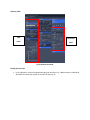
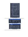
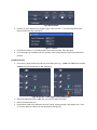
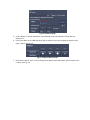
CONFOCOR 3 User Manual
Location: MI 278, inner room # 5
Door Code: 514
Fig.1: Power Switch
Startup:
1. Turn on the 2 switches behind the monitor to start the microscope and the lasers. (See Fig 1)
2. Turn on the power switch for the PC and then log in with username: administrator and
password: imaging
3. Start the ‘Zen 2007’ software. Then click the ‘Start System’ button.
4. Lower the microscope objective all the way down till the ‘Lower z-limit’ message shows on the
microscope panel. Then change the objective to the 40x Water. Add a drop or 2 of DI water and
then place the sample in the holder. Raise the objective so that it just touches the bottom of the
sample chamber. Place the cover on top of the sample and then lower the microscope head.
5. In ‘Zen’ turn on the 488 and/or 561 laser line(s). (The 488 line needs to be first set to ‘standby’
before the ‘On’ option is enabled) (See Fig.2)
Fig.2: Laser Controls
Software View:
LSM
Confocor3
Panel
Panel
Fig.3: Software overview
Finding the Coverslip:
1. In the LSM panel, choose the appropriate light path and filters. E.g.: 488 excitation, NT 80/20, BP
465-510IR and a low laser power of around 0.2% (See Fig. 4)
Fig. 4: Sample Light Path
2. Choose scan mode: Line, Pinhole: 1 AU, Gain of 100-300 (don’t want spikes) (See fig.5 and 6)
Fig. 5: Scan Mode Settings
Fig. 6: Pinhole Settings
3. Click ‘New’ to open a new window and then choose ‘Line Scan’. (See fig. 7)
Fig.7: Main Controls
4. Increase ‘z’ of the objective till you get a signal. Then zero the ‘z’. You have now located the
bottom of the coverslip. (See fig. 8)
Fig.8: ‘z’ control
5. Go up about 125um in ‘z’ to find the other end of the coverslip. Then zero again.
6. For a 3D sample, go up 300um into the solution. If 2D, sample will be a few microns above this
position.
FCS Measurement:
1. Go to the 3rd panel (Confocor3) and set up the beam path. E.g.: 1 color: HFT 488/561 and LP505;
2 Color: NFT 545, BP 505-540, LP 580. (See fig. 9)
Fig.9: On the left: 1 color, Right: 2 color sample paths
2. Select the appropriate lasers (488, 561, etc.) and use about 1% power
3. Start the pinhole with 1AU
4. Each pinhole needs to be calibrated. Use the ‘coarse’ setting and then ‘auto-adjust’ the ‘x’ and
‘y’ for each. When it’s done, save the adjustment. (See fig. 10)
Fig. 10: Pinhole settings
5. Under ‘Measure’, choose ‘Acquisition’ and set bleach time to 0s, Measure Time to 10s and
Repeat to 5s.
6. Click ‘Count Rate’ to see CPM and count rates to make sure you are studying the sample in the
right ‘z’ plane. (See Fig. 11)
Fig.11: Confocor Main Controls
7. Click ‘New’ and then ‘Start’ to start taking FCS correlation data. When done, save the data in the
E:/ drive. (See Fig. 11)