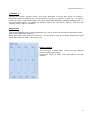
1
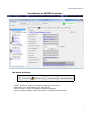
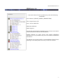
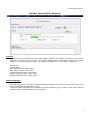
ENTTEC RDM Controller 2.5
Conforms to RDM Standard ANSI E1.20 -2006
Software Manual
www.enttec.com/rdm
Version 2.5
01/11/2007
1
ENTTEC RDM Controller 2.5
Controller Features
Acts as a true RDM Controller, using USB PRO as hardware
Discovers all RDM enabled responders on the line.
Allows control over each responder individually
Send RDM Get/Set to the selected responder
Displays Responder Device Information Summary
Supports multiple sub-devices for each responder found.
Allows RDM Get/Set messages to be sent in various Formats
DMX Patching, DMX fading, and other Controls for RDM enabled responders.
Sensors, Status Messages displayed in easier to read user-interface
Device List allows Drag & Drop DMX Patching as well as Auto Patch
Description
This documentation covers all the features and usage instructions for ENTTEC Controller Tool. It is
recommended that you read the entire manual before using the Controller to control RDM based
responders in your setup.
ENTTEC RDM Controller is fully ANSI E1.20 Compliant, and relies on the RDM Protocol stack
developed by ENTTEC. The Controller Graphical User Interface makes it easy and fast to
communicate with compatible (ANSI E1.20) devices which act as responders over the line.
The GUI is divided into four functional areas, namely:
Device Summary: Useful information reported by the device
DMX Patch Grid: DMX Patching via drag & drop
Device Monitor: Sensor information & Status Messages
Advanced RDM Settings: RDM Get & Set for all supported Parameters
2
ENTTEC RDM Controller 2.5
Introduction to ENTTEC Controller
Tab-based windows
Device Summary: Useful information reported by the device
DMX Patch Grid: DMX Patching via drag & drop
Device Monitor: Sensor information & Status Messages
Advanced RDM Settings: RDM Get & Set for all supported Parameters
3
ENTTEC RDM Controller 2.5
Connection: PRO Hardware
To operate ENTTEC RDM Controller a DMX USB PRO or a RDM USB PRO is required. Both devices
must have Firmware v2.xx to run the RDM Controller.
Controller will work in Full Version with all features available only in the following setup:1) Using RDM USB PRO with Firmware v2.XX
OR
2) Using DMX USB PRO with ENTTEC Dongle
For more information please look in Troubleshooting section .
For Demonstration/ evaluation of the software ENTTEC Controller can also be used with a DMX USB
PRO with limited functionalities (no Dongle required). The Lite version only allows Discovery and
access to the Device Information Tab.
After connecting a RDM USB PRO to the PC using an available USB Port, open the Controller
Application and click on Devices menu and all the connected PROS shall be listed under this menu.
Click on the selected device to allow the Controller to connect to the PRO.
PRO Status
Following graphics are used to highlight the current state of any PRO connected with the
Controller:Initial State.
Selected PRO successfully connected
Wrong Firmware on PRO
(2.xx is correct)
A previously connected PRO is not
anymore
connected
If the connection is not made correctly an error window will pop-up which could mean an I/O Error.
In that case, try selecting the device again from the Device menu, and if it again shows an error,
close the Controller tool, reconnect the PRO to the PC, and restart Controller and try to connect
again.
4
ENTTEC RDM Controller 2.5
RDM Discovery
ENTTEC Controller is designed to be used primarily for controlling Responders on the DMX network.
A requisite step for RDM Controller is to find any such devices on the network. The “Discovery”
button does this.
On activating “Discovery”, the status changes to “Discovery in Progress”. Since discovery could take
up to a few seconds depending upon the number of RDM responders on the network, it can be
canceled by the “Cancel” button if needed.
On completion of discovery, the Device List is updated with the Device UID of the responders that
have been found.
Full Discovery
A full Discovery, clears the existing Device List, Un-Mutes all the responders connected to the
Controller, and then goes through the RDM Discovery process. Upon completion all devices found
are added to the Device List, along-with any sub-devices.
Recommended for finding all Devices in your set-up. It may take a while, depending on the number
of responders, but it will always find all compatible RDM responders.
Add. Discovery
Add. (Additive) Discovery, does not clear the existing Device List, it just goes through the RDM
Discovery process. Upon completion any additional devices found are added to the Device List,
along-with any sub-devices.
Recommended if any new responders are added to a current set-up and you want to quickly find the
newly added responders in your set-up.
Note: Since “Add. Discovery” doesn't Un-mute the responders before doing discovery, it will only
find the responders which are already un-muted.
5
ENTTEC RDM Controller 2.5
RDM Device List
Lists each device found via discovery with the following
attributes:Device Name (DEVICE_MODEL_DESCRIPTION)
UID: Unique Device ID
Desc: Device Model ID
DMX Start Address
DMX Footprint
And all the sub-devices reported by any device are shown
under that device with its own attributes.
Double Clicking on each device will toggle hide/show
attributes for it. By default only the first device's attributes
are shown.
The Device List is also useful in accomplishing drag & drop
patching in the DMX patch Grid only in the Full Version
6
ENTTEC RDM Controller 2.5
Device Summary
It Includes all the major information form the DEVICE_INFO response, and gives the user the ability
to change DMX Start Address and DMX Personality. It also shows the RDM Parameters supported by
the device, with the default/required Parameters (as per ANSI E1.20) shown in black.
Once the device information is loaded on the panel for one particular device, the controller
application's information about that device must be refreshed manually to keep it up-to-date,
especially where conditions at the device may be subject to change.
7
ENTTEC RDM Controller 2.5
DMX Patch Grid (Full Version)
The DMX Patch Grid panel contains a grid displaying all possible output addresses (also referred to
commonly as "DMX Channels"). This allows user to patch devices and see the results graphically.
There are also several buttons assist in the patching operation and to allow on-the-fly control of the
dimmers or attributes of a multi-channel fixture.
The Drag & Drop technique is available in this window, and is considered the easiest way to
configure the selected device to output on the chosen DMX Channel (or to "address" it.) If you're
already familiar with "drag and drop" just drop the selected device onto the Channel you want its
Start Address to be.
If you're not as familiar with it, here's a refresher. This procedure requires three steps.
1) place the mouse over the fixture you wish to patch in the list at the left.
2) press the left mouse button down and hold it while moving the mouse to the chosen square on
the right side
3) release the mouse over the square corresponding with the number to which you wish it patched.
8
ENTTEC RDM Controller 2.5
DMX CHANNELS GRID
The channels patched are shown in the following colors:Patched to a device on the list. (DARK GREEN)
Vacant Cell / Not Patched yet (WHITE)
Overlapped with 2 or more devices (RED)
Patched to the currently Selected Device (LIGHT GREEN)
Overlapped And Patched to the currently Selected Device (PINK)
Patching Channels to a device
When patching your devices, if you select (by
dropping) a channel which is already patched, you
will be prompted by a message window that an
Overlap may occur.
Decide whether you wish to
proceed anyhow or choose another location.
Auto Patch
Auto Patch will patch all the devices shown on the list, to a series of channels starting with DMX
1. The devices will be patched consecutively based on the Sort order of their Manufacturer Label
Save Patch to All
Using the Manual Patch and Auto Patch functions of the
program will display your new choices in the grid, but those
changes will not communicated to the devices until you
issue a command to do so.
To save the changes made, click on the "Save Patch to All"
button. Once all the devices have learned their new
configurations and responded that they are ready, a prompt
will appear showing the status. If anything prevented the successful patching of the entire list, a
warning message will appear instead, saying “Not all devices were patched”.
Export List
This command exports the Device List in a csv format. The fields included are:
Device UID; Device Label; Manufacturer Label; and DMX Start Address.
This csv file can then be loaded into other programs such as Microsoft Excel or for formatting and
printing.
9
ENTTEC RDM Controller 2.5
[ Identify ]
Identify:This button toggles on/off, and when activated it forces the device to exhibit a
distinctive behavior designed by its manufacturer to help you locate it in your rig. To explore
this more deeply, what really happens is that it sends RDM IDENTIFY_DEVICE message (SET =1)
to the selected device. To disable the Identify feature for that device (SET=0), just click the
Identify button again to release it.
Import List
This button imports from a comma delimited (csv) file, a device list having the following format :
Device UID, DMX Start Address, ……………….
Using this feature will update the devices in the device List with a new Start Address for anyof
them that match the UID in the import List.
Device Control
This will open a DMX Fader control for the selected
device. Changing the fader
values will send live DMX level information over the
network.
10
ENTTEC RDM Controller 2.5
Monitor Devices (Full Version)
Sensors
This section of the Monitor Devices Tab window displays all sensors reported by the device
selected in Device List to the left. The Sensor display area is scrollable if there are multiple
values to scan. The program shows the following information for each sensor displayed:
Sensor No.
Sensor Name
Min. Defined Value (with units)
Max. Define Value (with units)
Lowest reported Value (with units)
Current reported Value (with units)
Highest reported Value (with units)
Status Messages
Any Warning, Error or Advisory Status Messages reported by the device are listed in this area.
Critical messages are displayed in red.
Currently these messages are updated by manual refreshing, but in future version auto-refresh
options will be made available for convenience.
11
ENTTEC RDM Controller 2.5
Other Information
There may or may not be other useful information displayed, depending on whether the device
supports the following Parameter Ids:DEVICE_HOURS
LAMP_HOURS
LAMP_STRIKES
LAMP_STATE
DEVICE_POWER_CYCLE
Advanced RDM (Full Version)
The final panel of the Controller program is the Advanced RDM features. Here there is the
opportunity to perform GET/SET functions for all supported Parameters as reported by the device.
Since not all PIDs allow both GET and SET. and since they may or may not have data to send, the
relevant controls for each device are pre-selected based on the ANSI E1.20 specification. Once a
different device is selected, the list of PIDs that can be GET or SET will change accordingly.
12
ENTTEC RDM Controller 2.5
RDM GET/SET Controls
Data-Type Selection :- String,Byte,Short,Long,Array
Data-Format Selection:- Default,HEX
Data Field
Get/Set Button: Sends the request to responder.
RDM Log Messages
The Log Window displays the ongoing RDM Communication and the response received in
either Text / Hex format.
Troubleshooting
Full Version
The RDM ENTTEC Controller can only be operated in full-version by either of the two
methods:(a) using DMX USB PRO and the ENTTEC Key Dongle. The
dongle must be connected to the PC at all times, and
before starting discovery
(b) using RDM USB PRO with firmware v2.xx
Missing RDM Responses
Please ensure that the responder(s) talking to the Controller are ANSI E1.20 compliant,
and respond within the allowed time. ENTTEC RDM Sniffer (www.enttec.com/rdm) can be
used to determine whether the RDM Communication is taking place as it should.
DMX USB PRO problems
Ensure you are using the correct Firmware 2.xx with Controller.
For more info visit (www.enttec.com/dmxusbpro)
PRO - Driver problems
If Windows XP/2K crashes or becomes unresponsive, reporting a USB Driver issue,
following is the workaround outlined here :- http://support.microsoft.com/kb/283063
A quickfix for the above is to disable the "serial enumerator" for the device:You can find it under
Device Manager -> Com ports -> Select PRO (properties) -> Port Settings -> Advanced
Look for "serial enumerator"
Disable it and the problem should go away
Other Problems
If you are having problems with Discovery, or any other issues please feel free to ask our
support team. (http://www.enttec.com/support-center)
13
ENTTEC RDM Controller 2.5
Appendix A: Definitions (as per ANSI E1.20)
Acknowledge: a response to a request that indicates if the request was successful, and if
not, why the request failed.
Controller: in any segment of an RDM communication system, only one device is free to
initiate data transmissions. This device is termed a Controller.
Discovery: the process of finding RDM devices in an RDM communication system.
Device: a piece of electrical or electronic equipment attached to an RDM communication
system capable of transmitting, receiving and/or passing RDM messages.
Parameter/ PID: a device attribute about which requests are sent and responses are made.
Root Device: the top level device in a piece of equipment containing, either physically or
logically, sub-devices. An example of a root device is the top level rack controller in a dimmer
rack.
Sub-device: a device contained, either physically or logically, in another device. Individual
sub-devices do not have UID's, but are referred to by using the root device's UID. A dimmer that
is part of a dimmer rack is an example of a sub-device.
Unique ID (UID): a number used to uniquely identify a device.
14
ENTTEC RDM Controller 2.5
15