1
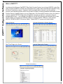
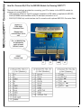
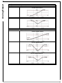
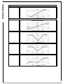
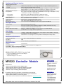
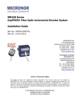
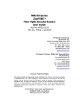
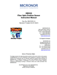
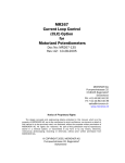
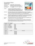
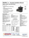
MR320
MICRONOR
automation components
Products
ZapFREE® Incremental Encoder CONTROLLER Module
The MR320 ZapFREE® Controller module is the active half of the
MR320 series ZapFREE® Fiber Optic Incremental Encoder
System. The module incorporates multiple built-in interfaces for
compatibility with PLCs, motor drives and other motion control
systems.
• Mounts on standard 35mm DIN Rail
• Operates from +15C to +32 VDC power supply
• A/B quadrature outputs – line driver and push-pull
• Two programmable analog outputs (4-20mA and ±10V)
• USB, Modbus RTU or RS422/RS485 serial interface
Features
• RS232 connections available with optional adapters
Inherently Safe Optical Radiation
[Ex op is I/II Ga]
• All optical, passive sensor does not
emit EMI
• Sensor is immune to EMI, RFI,
lightning and ground loops
• Interference-free transmission up
to 2500 meters (8000 feet)
• Sensor is ATEX classified as
“Simple Apparatus” and
is
approved for use in all types of
hazardous locations and explosive
atmospheres (gas and dust),
including mines and oil rigs.
System Planning
• Multiple built-in interfaces
1.
2.
Verify that the optical link loss is within system’s two-way loss margin of 12.5dB
�
Account for losses of inline connectors, splices and cable
�
For example, 4 interconnections (0.5dB each) over 400-meter (3dB/km) = 6.4dB
Follow industry-specific FOLAN component selection and installation guidelines
�
Always follow bend radius, flex, clamping and routing conventions.
�
Recommend industrial-grade PUR cable and connectors for industrial environments
ZAPPY™ Configuration Software
What is ZAPPY™?
As delivered, the Micronor ZapFREE™ Fiber Optic Encoder System (consisting of MR320 series fiber
optic encoder and MR320 module) are preprogrammed, ready to be connected and operated using
the Direct Quadrature outputs. However, many user applications intend to use the auxiliary
functions and operating modes within the encoder firmware, including Quadrature Multiplier/Divider,
Position Counter, Analog Outputs or to run Diagnostics. For these latter functions, the user needs to
use the supplied ZAPPY™ Configuration/Diagnostics program to perform a one-time setup for
configuring functions. The software is designed to run on a PC running under Windows XP or later.
The PC can be connected to the MR320 module, via USB or RS232 COM port (with optional
MR232-1 RS485-to-RS232 Converter Cable). Typical ZAPPY™ screens are shown below:
Start-Up Screen
Encoder Parameters Display Screen
Real-Time Diagnostics Screen
Internal Diagnostics Screen
Online Instructions
MR320 and ZAPPY™ Connections
How Do I Connect My PC to the MR320 Module for Running ZAPPY™?
There are three methods provided for connecting your PC or laptop to the MR320 module for
purposes of running ZAPPY ™:
• USB interface via built-in Type B connector receptacle (a USB cable is supplied with MR320)
• RS422/RS485 serial interface via RX/TX serial port connection on J3
• RS232 (PC COM Port) serial interface via J3 connection with optional MR232-1 Converter Cable
Analog Outputs
How do I interface the MR320 to my motion control system?
The MR320 offers a broad array of standard encoder/motion control interface options:
• A/B push-pull quadrature outputs (typically used for 24V inputs)
• A/A’/B/B’ line driver quadrature outputs (also TTL compatible)
• Fully programmable 4-20mA analog output, configurable for speed or position output
•
Fully programmable ±10V analog output, configurable for speed or position output
• RS422/RS485 serial interface using commands and protocols described in Technical Manual/User
Guide. You can download the full technical manual via the “manual” link for the MR320 at
www.micronor.com
How do I setup the parameters for operating the Analog Outputs?
The two analog outputs can be independently configured as a Speed (RPM) or an absolute Position indicator.
Any Full Scale value >0 will activate the output. The Mode defines which Function the output performs. Each
analog output is followed by a programmable low pass Filter. Consult following summary or MR3XX User Guide
for details.
How Do I Program The Voltage or Current analog outputs for Speed (RPM)?
•
•
•
•
Encoder Direction (Register 2B) accepts values of 0=CW (default) and 1=CCW
Output Function (Voltage register 23 and Current register 26)
o See following page for output modes available
Full Scale value (Voltage register 24 and Current register 27)
o 0 turns the Voltage analog output OFF – regardless of selected Output mode
o Accept full scale value of 10-10,000 (RPM)
Filter values (Voltage register 25 and Current register 28)
o Value 0 corresponds to no filtering
o 1-256 correspond to the 3dB filter point per equation provided in the Technical Reference
Analog Output
o
Voltage SPEED Mode (Register 23)
0
1
Current SPEED Mode (Register 26)
0
1
2
Analog Output
How Do I Program The Voltage and/or Current Analog Output for POSITION?
•
•
•
•
•
•
•
•
Encoder Direction (Register 2B) accepts values of 0=CW (default) and 1=CCW
Output Function ( Voltage register 23 and Current register 26, see table below for output
functions)
Full Scale value (Voltage register 24 and Current register 27)
o 0 turns the Current Voltage analog output OFF – regardless of selected Mode
o Accepts full scale value of 1-8,388,607 counts
Filter values (Voltage register 25 and Current register 26)
o 0 corresponds to no filtering
o 1-256 correspond to the 3dB filter point per equation provided in the Technical Reference
o Default value is 32 (corresponding to 10Hz)
Counter Reset mode (Register 29)
o 0 = Counter is reset on first rising edge of RESET input
o 1 = Allows debounce period of 60ms
Counter Multiplier mode (Register 2A)
o 0 = Normal counting (every cycle is one count)
o 1 = Allows ½ quadrature cycle to increment/decrement internal Counter – effectively
doubling the position resolution.
Hardware Reset Value (Register 2C)
o Internal Counter resets to this value when RESET input is activated
o Accepts input value of 0-8,388,607
o Sometimes this function is also called “homing”
o Analog output value will be determined by Mode selected. Here is an example:
•
Reset On Count/Homing mode (Register 2D)
o Internal Position Counter is automatically reset to 0 whenever its absolute value matches
this preprogrammed value
o 0 = mode deactivated
o Accepts input value of 1-8,388,607 for active mode. Here is an example:
Analog Output
Voltage POSITION Mode (Register 23)
2
Current POSITION Mode (Register 26)
3
4
5
6
Specifications
Functional and Electrical Interface
DIRECT Quadrature Outputs
Bandwidth
Format
POSITION COUNTER Range
DIVIDER Quadrature Outputs
Analog Outputs
Current Output:
Voltage Output:
RS422/485 Interface
RS232 Interface
Modbus interface
USB interface
Electrical Connections
70kHz max. (Contact Micronor concerning modifications for higher bandwidth applications.)
A/B Push-Pull and A/A’/B/B’ RS422 Line Driver
Direction/Sign Bit plus 24-bit counter value (±8,388,607, equivalent to 8,192 revolutions with
MR324 1024ppr encoder). Both software and hardware Zero (calibration) Set available.
DIVIDER range is 2-128. A/A’/B/B’ Line Driver (A/B Push-Pull available as option,)
Each output is individually programmable for POSITION (full-scale range of 1-8,388,607 counts)
or SPEED (full-scale range of 10-10,000 RPM)
Range: 0mA to 24mA, Max Burden Resistance: 500Ω (24V supply)
Range: ±12V; Max Current: 5mA (2kΩ load); Short Circuit < 5 seconds
Direct connection via J3, also Modbus (RTU) compatible)
With optional MR232-1 Converter Cable
Modbus (RTU) compatible RS422/RS485 interface
USB, disables RS485/Modbus interface when used
J1, J2 J3 connections via WAGO QuickConnect Plugs (supplied with MR320)
Fiber Optic Interface
Connector Type
Fiber Type
Maximum Optical Link Length
Duplex LC plug with Super PC Polish
Performance Requirements: IL<0.5dB, RL>24dB, Telecordia GR-326 Endface Geometry
2 x Multimode 62.5/125, Graded Index, 0.275NA
Maximum of 2500 meters (8300 ft) or 2-way optical loss of 12.5dB at 850nm
(Contact Micronor for longer distance requirements)
Power Supply
Power Supply Input
+5V Output
+15VDC to +32VDC, 60mA (During Power Up, power supply should be capable of delivering a
momentary current in excess of 100mA.)
10mA maximum load. (Designed for powering MR232-1 RS485/RS232 adapter cable)
Environmental Performance
Temperature/Humidity
-5° to +55°C / 30% to 85% RH (non-condensing)
Seal Rating
ATEX Rating
IP40
[ Ex op is 55°C/T6 ] per IEC 60079-28.
Physical Attributes
Mounting
Housing Dimensions
35mm DIN Rail
102mm W x 102mm D x 68mm H (/ 300g (10.5oz)
Specifications Subject To Change Without Notice
MR232-1 RS422/485 to RS232 Converter Cable
Ordering Info
• Interconnects MR320-J3 and a PC’s 9-pin COM port
• Length, 3 meters (nominal)
• Temperature Range: +5° C to +30° C
MR320 Controller Module
Related Items:
•MR232-1 RS422/485-to-RS232 Adapter Cable
•MR322, MR324, MR326 or MR328 ZapFREE® Encoders
•MR320-D06Cxx Duplex LC Fiber Optic Cable Assemblies
•MR320C Duplex LC Mating/Bulkhead Adapter
For additional technical information, contact Micronor and request:
•MR310-MR320 ZapFREE™ Fiber Optic Encoder System User Manual
•MR320 ATEX Declaration of Conformity Report
•Data sheets and User Guides can also be downloaded from www.micronor.com
MR320 Data Sheet, Document 98-0320-10, Revision C, Released 7-Oct-2015
MICRONOR INC.
900 Calle Plano, Suite K
Camarillo, CA 93012
USA
T +1-805-389-6600
F +1-805-389-6605
[email protected]
www.micronor.com
MICRONOR AG
Pumpwerkstrasse 32
CH-8105 Regensdorf
Switzerland
T +41-44-843-4020
F +41-44-843-4039
[email protected]
www.micronor.com