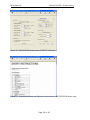
1
MR3XX Series ZapFREE™ Fiber Optic Encoder System User Guide Doc No: MR310-135 Rev: E1: FINAL 1-12-2009 For Support in Americas: MICRONOR INC. 3483 Old Conejo Road, Suite 203 Newbury Park, CA 91320 USA PH: (805) 499 - 0114 FX: (805) 499 – 6585 [email protected] www.micronor.com For Support in Europe, Middle East, Asia and Africa: MICRONOR AG. Pumpwerkstrasse 32 CH-8105 Regensdorf Switzerland PH: +41-44-843-4020 FX: +41-44-843-4039 [email protected] www.micronor.com Notice of Proprietary Rights The design concepts and engineering details embodied in this manual, which are the property of MICRONOR INC., are to be maintained in strict confidence; no element or detail of this manual is to be spuriously used, nor disclosed, without the express written permission of MICRONOR INC. All rights are reserved. No part of this publication may be reproduced, stored in a retrieval system, or transmitted in any form or by any means, electronic, mechanical, photocopying, recording, or otherwise, without prior written permission from MICRONOR INC. © COPYRIGHT 2004-2009, MICRONOR INC. NEWBURY PARK, CALIFORNIA UNITED STATES OF AMERICA MICRONOR INC. MR310 ZapFREE™ Encoder System Revision History Rev X1 Initial Draft Rev A Rev A1 First Release for use with MR310 PCB RevA and Zappy 1.1 First Release for use with MR310 PCB RevA and Zappy 1.2 Rev B Revision for use with MR310 RevB, MR312 RevA and new MR314 RevA Rev B1 Minor revisions and typo fixes Rev C Beginning with MR310 firmware 0.6 and above, MR310 has additional functions and mode extensions: • Added POSITION mode 2 to Voltage Mode (Register 23) and extended Voltage Scale setting to 9,000,000 (Register 24, corresponds to range of internal Position Counter) • Added POSITION modes 3-5 to Current Mode (Register 26) and extended Current Scale setting to 9,000,000 (Register 27, corresponds to range of internal Position Counter) • Added Position Counter Reset hardware input via J1/Pin-11 and Position Reset (signal debounce) mode (Register 29) • Added Quadrature Multiplier mode (Register 2A) ZAPPY 2.X is compatible with earlier MR310 firmware. When trying to program the MR310 (using [SAVE TO MR310]), ZAPPY simply returns an error message. Under serial software control, the MR310 will return an error code. Rev D Added ATEX and U.S. Hazardous Classifications to Specifications Added info about low SPEED limitations of analog outputs Added more info to the error codes section 7.5 Added MR321 Fiber Optic Cleaning Kit to sections 4 and 7.3 Rev D1 Added MR316 Encoder Added MR312A and MR316A mounting kits to section 5.2 Rev E Additional Functionality with MR310 Firmware Revision 1.18 and up. Added Current Position Mode 6 (Reg 26) Added Hardware Preset Value (Reg 2C) Added Auto Reset On Count (Reg 2D) Updated ZAPPY™ INSTALLATION SOFTWARE to V3.1 Updated as required to support MR310 V1.18 firmware and new modes Added [ANALYZE SYSTEM] to DIAGNOSTICS Rev E1 Added MR318 Encoder Added MR232-2 USB Adapter cable for running Zappy on a PC without available serial COM port. Correction to Specifications and other I/O references: RESET Input, change from TTL input to PLC-type 24V logic input A/B Quadrature Outputs, change from Open-Collector to Push-Pull Page 2 of 80 MICRONOR INC. MR310 ZapFREE™ Encoder System Table of Conten ts 1. Product Description ............................................................................................... 6 2. Warranty Information ............................................................................................ 8 2.1 2.2 3. Specification........................................................................................................... 9 3.1 3.2 3.3 3.4 3.5 4. MR312 ZapFREE™ Rotary Encoder Specifications ..................................... 9 MR314 ZapFREE™ Rotary Encoder Specifications ...................................10 MR316 ZapFREE™ Rotary Encoder Specifications ...................................11 MR318 ZapFREE™ Non-Metallic Rotary Encoder Specifications .............12 MR310 Remote Encoder Interface (REI) Module Specifications .............13 Initial Preparation ................................................................................................15 4.1 4.2 4.3 5. Limitations of Warranty ................................................................................. 8 Contact Information ....................................................................................... 8 Unpacking and Inspection ...........................................................................15 Damage in Shipment ...................................................................................15 Standard Contents........................................................................................15 Installation Guidelines ........................................................................................16 5.1 System Planning ...........................................................................................16 5.2 Mounting the MR312/MR316, MR318 Rotary Encoders with Shaft ......17 5.3 Mounting the MR314 Hollow-Shaft Rotary Encoder .................................19 5.4 Mounting the MR310 REI Module...............................................................21 5.5 Making Connections to the MR310 REI Module........................................21 5.6 Fiber Optic Cable, Connections and Routing..............................................26 5.7 First Time Start-Up ........................................................................................27 5.8 Manual Gain Calibration (Manual Reset) ...................................................27 5.9 ZAPPY ™ Installation and Setup Software ..................................................29 5.8.1 Initial Performance Verification with ZAPPY™ ..................................30 6. Operation and Description of Functions ...........................................................36 6.1 Block Diagram ..............................................................................................38 6.2 Firmware Functions and Programming ......................................................40 6.2.1 Serial Interf ace Specification ..............................................................40 6.2.2 Communications Protocol ...................................................................40 6.2.3 The Block Check Character <BCC> .....................................................42 6.3 Configuration Commands and Parameters ...............................................42 6.3.1 Configuration Commands (Registers 10-19) .....................................44 6.3.2 User Commands (Registers 20-2A).....................................................45 6.3.3 Diagnostic Commands (Registers 30-39) ..........................................47 Page 3 of 80 MICRONOR INC. MR310 ZapFREE™ Encoder System 6.4 Communications/Programming Example .................................................47 6.5 Detailed Description of Eac h Function .......................................................49 6.5.1 Counter (Register 20) ...........................................................................49 6.5.2 Divider (Register 21) ............................................................................49 6.5.3 RPM (Register 22) ................................................................................50 6.5.4 Voltage Mode (Register 23) .................................................................50 6.5.5 Voltage Scale (Register 24) .................................................................52 6.5.6 Voltage Filter (Register 25) ..................................................................53 6.5.7 Current Mode (Register 26) .................................................................54 6.5.8 Current Scale (Register 27) .................................................................58 6.5.9 Current Filter (Register 28) ..................................................................58 6.5.10 Counter Reset (Register 29) ................................................................59 6.5.11 Counter Multiplier (Register 2A) ..........................................................60 6.5.12 Encoder Direction (Register 2B) ..........................................................61 6.5.13 Hardware Reset Value (Register 2C) ..................................................62 6.5.14 Reset On Count/Homing (Register 2D) .............................................63 6.5.15 Saving Parameters in EEPROM (Register 13)....................................64 7. Maintenance and Service ...................................................................................65 7.3 Encoder Will Not Produce Q uadrature Signals ..........................................65 7.1.1 LED’s Do Light Up .................................................................................65 7.1.2 LED’s Do NOT Light Up .........................................................................65 7.2 Serial Interf ace..............................................................................................66 7.2.1 Testing The Interface Cable .................................................................66 7.3 Fiber Optic Connector Cleaning...................................................................67 7.3.1 WET Cleaning Method ..........................................................................68 7.3.2 DRY Cleaning Method - Micronor MR321 DRY Cleaning Kit ............68 7.4 Troubleshooting ............................................................................................69 7.4.1 Verify MR310 Operation using ZAPPY™ Software ............................69 7.4.2 Verify Visual Continuity of Fiber Optic Cable Link..............................70 7.4.3 Verify Optical Output Power of MR310 Module.................................70 7.4.4 Verify Loss Condition of the Optical Cable Link .................................71 7.4.5 Built-In System Analysis of Complete Fiber Optic Encoder System and Link 72 7.5 Blinking Error Codes .....................................................................................74 8. Reference Drawings ............................................................................................75 List of Figures Figure 1. Shafted Encoder Face Mount via Counter-Bored Panel ............................18 Figure 2. Shafted Encoder Mounting via Thru-Hole With Synchro Clamps ..............19 Figure 3. Hollow Shaft Encoder Mounting Options For MR314 and ENI100 (ENI100 shown in pictures).............................................................................................................20 Page 4 of 80 MICRONOR INC. MR310 ZapFREE™ Encoder System Figure 4. MR310 Mounted On A DIN Rail...................................................................21 Figure 5. Diagram of Connections to MR310 Interface Module...............................23 Figure 6. How To Manual Reset The MR310.............................................................24 Figure 7. How To Insert and Remove Wires From the WAGO Plug...........................25 Figure 8. Inserting/Removing the WAGO Plug From The MR310.............................25 Figure 9. ST-to-ST Fiber Optic Cable Assembly and ST-to-ST Mating/Bulkhead Adapter ................................................................................................................................26 Figure 10. How to Manually Reset the MR310..........................................................28 Figure 11. Photograph of MR232-1 RS422/RS485-to-RS232 Adapter Cable. ......29 Figure 12. HOME Page of ZAPPY™ Setup Software...................................................30 Figure 13. ENCODER Table View Screen via ZAPPY™ Software...............................31 Figure 14. Initial OPERATE Screen via ZAPPY™ Software.........................................33 Figure 15. Real-time Encoder Operation viewed vi a OPERATE Screen....................34 Figure 16. DIAGNOSTICS Screen view via ZAPPY™ Software...................................35 Figure 17. Online Instructions and Reference Information in INSTRUCTIONS Screen view. ................................................................................................................................35 Figure 18. Block Diagram of the ZapFREE™ Fiber Optic Encoder System..............39 Figure 19. Set-up Parameters for HYPERTERMINAL Program..................................67 Figure 20. Dirty and Clean Fiber Optic Connector Ferrule and Endface Views. ......68 Figure 21. WET Cleaning Method Requires IPA & Dry Wipes OR Pre-Wetted Wipes & Dry Wipes. ....................................................................................................................68 Figure 22. MR321 Fiber Optic Cleaning Kit...............................................................69 Figure 23. Verifying Optical Continuity With A Visual Fault Locator..........................70 Figure 24. Measuring Optical Power Output Of The MR310 Module.......................71 Figure 25. SYSTEM ANALYSIS Screens in ZAPPY™ DIAGNOSTICS Mode...............73 Page 5 of 80 MICRONOR INC. 1. MR310 ZapFREE™ Encoder System Product Description The MR312/MR314/MR316/MR318 ZapFree™ Rotary Encoders (U.S. Patent 7,196,320) are the world’s first totally passive, fiber optic rotary encoder – the ideal EMI-immune sensor solution for all kinds of harsh and hazardous environmental applications. The ZapFREE™ Encoders offer immunity to lightning and atmospheric static that would “zap” conventional encoders; outdistances copper cable – allowing link lengths to 1000 meters; ATEX certified for use in manner of hazardous and explosive environments; and inherent EMI/RFI resistance for medical applications and other “noisy” industrial applications. There are no integral electronics within the encoder housing and the all-optical design requires just a single optical fiber connection – the utmost in simplicity, reliability and ease of installation. Features of the ZapFREE™ Rotary Encoders include: • • • • • • • • • MR312 is a Size 58mm shaft encoder with 100/128/256/360ppr options MR316 is a Size 90mm shaft encoder with 100/128/256/360ppr options and IP67 environmental seal for wash down and short immersion. MR314 is Size 100mm hollow shaft encoder with 1024ppr resolution MR318 is a non-metallic Size 58mm shaft encoder with 360ppr resolution Totally passive – requires just a single-fiber 62.5/125 multimode fiber connection ATEX certified as “Simple Apparatus” and usable in all types of hazardous locations STANDARD temperature range is -40/+80°C. EXTENDED option covers -60/+150°C Industry standard ST-PC optical interconnect. Special harsh environment optical interconnects available as option. Downstream, the MR310 Remote Encoder Interface (REI) module converts the optical signals to industry standard quadrature signal and is available in both the push-pull and line driver output configuration for connection a PLC, counter or computer interface board. Two programmable analog outputs (±10V and 4-20mA) offer additional feedback options. A serial interface (RS485 or RS232) is also available for computer control and programming. For convenient packaging into standard control systems, the MR310 is offered in a standard DIN-rail mountable module and uses readily available +15-32 VDC/60mA power for operation. It doesn’t get any simpler to design into your system. Features of the MR310 ZapFREE ™ Interface Module: Page 6 of 80 MICRONOR INC. • • • • • • • • MR310 ZapFREE™ Encoder System Easily co-located with PLC or motor drive electronics in non-hazardous, control room environment – allowing actual electrical connections to be simple, short and EMI resistant Mounts on standard 35mm DIN rail Operates from readily available +15 to +32VDC power supply Direct quadrature outputs – both A/B push-pull and A/A’/B/B’ line driver Programmable divider function with dedicated set of quadrature outputs – Line driver outputs is standard (push-pull is optional) Two analog outputs (4-20mA and Voltage) are independently programmable and scalable to output based on SPEED or POSITION Direct computer control via selectable RS232 or RS485 serial interface cable Quick Disconnect Terminal Blocks for efficient wiring Page 7 of 80 MICRONOR INC. MR310 ZapFREE™ Encoder System 2. Warranty Information MICRONOR INC. warrants this product to be free from defects in material and workmanship for a period of 1 (one) year from date of shipment. During the warranty period we will, at our option, either repair or replace any product that proves to be defective. To exercise this warranty, write or call your local MICRONOR INC. representative, or contact MICRONOR INC. headquarters. You will be given prompt assistance and return instructions. Send the instrument, transportation prepaid, to the indicated service facility. Repairs will be made and the instrument returned transportation prepaid. Repaired products are warranted for the balance of the original warranty period, or at least 90 days. 2.1 Limitations of Warranty This warranty does not apply to defects resulting from unauthorized modification or misuse of any product or part. This warranty also does not apply to Fiber Optic Connector interfaces, fuses or AC line cords. This warranty is in lieu of all other warranties, expressed or implied, including any implied warranty of merchantability of fitness for a particular use. MICRONOR INC. shall not be liable for any indirect, special or consequent damages. 2.2 Contact Information In North America: Micronor Inc. 3483 Old Conejo Road Suite 203 Newbury Park, CA 91320 USA Phone: +1-805-499-0114 Fax: +1-805-499-6585 Email: [email protected] URL: www.micronor.com In Europe: Micronor AG Pumpwerkstrasse 32 CH-8015 Regensdorf Switzerland Phone: +41-44-843-4020 Fax : +41- 44-843-4039 Email: [email protected] URL: www.micronor.com Page 8 of 80 MICRONOR INC. 3. 3.1 MR310 ZapFREE™ Encoder System Specification MR312 ZapFREE™ Rotary Encoder Specifications Functional Specification: Description Resolution Max Speed Optical Interface Fiber Type Fiber Link Length Optical Loss Margin (Max) Environmental Specifications: Description Temp Range/ATEX Classification Specification 100, 128, 256 or 360 ppr models 8000 rpm (Mechanical Limit) Fixed ST Receptacle or Optical pigtail with ST-PC Plug MM 62.5/125μm, Graded Index, 0.275NA Up to 1000m (3280ft) 6.5dB (Two-way loss margin, MR312 to MR310) Specification “Intrinsically/Inherently Safe Simple Apparatus” STANDARD Option ATEX Rating U.S. Haz Rating -40° to +80°C Ex op is I/II 80°C/T6 Class I/II/II, AEx op is Group I/II/III 80°C/T6 , Zone 0/1/2/20/21/22, Division 1/2 EXTENDED Option ATEX Rating U.S. Haz Rating -60° to +150°C Ex op is I/II 150°C/T3 Class I/II/II, AEx op is Group I/II/III 150°C/T3 , Zone 0/1/2/20/21/22, Division 1/2 0% to 95% RH (non-condensing) IP 64 (Protected against dust, dirt, splashing water. Other IP protection ratings available upon request.) Humidity Seal Rating Mechanical Specifications: Description Shaft Max Shaft Loads System MTBF Housing Weight Specification ∅ 6mm OD x 5.5mm FLAT x 10mm L (0.236-in OD x 0.217-in FLAT x 0.393-in L Radial = 80N (18 lbf), Axial = 40N (9 lbf) 1.36E+06 hours (155 years) (Bearing Life calculated at 2,500 RPM and 50% of Maximum Radial/Axial Shaft Load) ∅ 58mm x 58mm L 210g (7.25 oz) Specifications subject to change without notice Page 9 of 80 MICRONOR INC. 3.2 MR310 ZapFREE™ Encoder System MR314 ZapFREE™ Rotary Encoder Specifications Functional Specification: Description Resolution Max Speed Specification 1024 ppr 3000 rpm (Pulse divider function de-activate d. All other func tions may be ac tive) 2750rpm Optical Interf ace Fiber Type Fiber Link Length Optical Loss Margin (Max) (Speed is limited with all functio ns activated) Optical pigtail with ST-PC Plug MM 62.5/125μm, Graded Index, 0.275NA Up to 1000m (3280ft) 6.5dB (Two-way loss margin, MR314 to MR310) Environmental Specifications: Description Temp Range/ATEX Classification Specification “Intrinsically/Inherently Safe Simple Apparatus” STANDARD Option -40° to +80°C Ex op is I/II 80°C/T6 Class I/II/II, AEx op is Group I/II/III 80°C/T6 , Zone 0/1/2/20/21/22, Division 1/2 EXTENDED Option -60° to +150°C Ex op is I/II 150°C/T3 Class I/II/II, AEx op is Group I/II/III 150°C/T3 , Zone 0/1/2/20/21/22, Division 1/2 0% to 95% RH (non-condensing) IP 65 (Protected against dust, dirt, splashing water and low pressure water jets. Other IP protection ratings available upon request.) Humidity Sealed Mechanical Specifications: Description Shaft Moment of Inertia System MTBF Housing Weight Specification ∅ 38mm ID Hollow Shaft Hole 209E-06 kg*m2 1.76E+09 hours (201,061 years) (Bearing Life calculated at 2,000 RPM) ∅ 100mm x 49mm L 655g (23 oz) Specifications subject to change without notice Page 10 of 80 MICRONOR INC. 3.3 MR310 ZapFREE™ Encoder System MR316 ZapFREE™ Rotary Encoder Specifications Functional Specification: Description Resolution Max Speed (360ppr) Optical Interf ace Fiber Type Fiber Link Length Optical Loss Margin (Max) Specification 100, 128, 256 or 360 ppr models 8,000 rpm(1) Fixed ST Receptacle or Optical pigtail with ST-PC Plug MM 62.5/125μm, Graded Index, 0.275NA Up to 1000m (3280ft) 6.5dB (Two-way loss margin, MR316 to MR310) Environmental Specifications: Description Temp Range/ATEX Classification Specification “Intrinsically/Inherently Safe Simple Apparatus” STANDARD Option ATEX Rating U.S. Haz Rating -40° to +80°C Ex op is I/II 80°C/T6 Class I/II/II, AEx op is Group I/II/III 80°C/T6 , Zone 0/1/2/20/21/22, Division 1/2 EXTENDED Option ATEX Rating U.S. Haz Rating -60° to +150°C Ex op is I/II 150°C/T3 Class I/II/II, AEx op is Group I/II/III 150°C/T3 , Zone 0/1/2/20/21/22, Division 1/2 0% to 95% RH (non-condensing) IP 66 Humidity Seal Rating (Protected against dust, dirt, splashing water, low pressure water jets and temporary immersion. Other IP protection ratings available upon request.) Mechanical Specifications: Description Shaft Max Shaft Loads System MTBF Housing Weight Specification ∅ 12mm OD x 25mm L with 4x20mm Keyway (0.236-in OD x 0.217-in FLAT x 0.393-in L Radial = 140N (31 lbf), Axial = 70N (15 lbf) 3.11E+05 hours (35.6 years) (Bearing Life calculated at 2,500 RPM and 50% of Maximum Radial/Axial Shaft Load) ∅ 90mm x 82.5mm L 615g (21.5 oz) Specifications subject to change without notice Notes: (1) Derate maximum speed by 100rpm per degree Celsius when operating above 60°C. Page 11 of 80 MICRONOR INC. 3.4 MR310 ZapFREE™ Encoder System MR318 ZapFREE™ Non-Metallic Rotary Encoder Specifications Functional Specification: Description Resolution Optical Interf ace Fiber Type Fiber Link Length Optical Loss Margin (Max) Specification 360 ppr Optical pigtail with ST-PC Plug, minimum length 5m (Pigtail length must be long enoug h so that metallic ST plug is outside of MRI environment.) MM 62.5/125μm, Graded Index, 0.275NA Up to 1000m (3280ft) 6.5dB (Two-way loss margin, MR318 to MR310) Environmental Specifications: Description Temp Range Specification Ambient laboratory environment Inherently safe optical radiation, “Simple Apparatus” 0% to 95% RH (non-condensing) Humidity Mechanical Specifications: Description Shaft Specification ∅ 6mm OD x 5.5mm FLAT x 10mm L (0.236-in OD x 0.217-in FLAT x 0.393-in L ∅ 58mm x 58mm L 280g (9.75 oz) - With 5m ST Pigtail) Housing Weight Specifications subject to change without notice Page 12 of 80 MICRONOR INC. MR310 ZapFREE™ Encoder System 3.5 MR310 Remote Encoder Interface (REI) Module Specifications Functional Specification: Description DIRECT Quadrature Outputs Bandwidth Format DIVIDER Quadrature Outputs Divider Range Format Analog Outputs Current Output: Voltage Output: POSITION Mode Internal Counter Counter Hardware Set-Reset SPEED Mode Serial Interface Fiber Link Length Electrical Connectors Power Supply Specifications: Description Power Supply Input +5V Output Specification Effective with V1.18 Firmware Only: 70 kHz max. (Contact Micronor concerning modifications for higher bandwidth applications.) A/A’/B/B’ Line Driver and A/B Push-Pull are Standard Programmable DIVIDER range is 2-9999 A/A’/B/B’ Line Driver standard (Push-Pull upon request) Each output is individually programmable for POSITION or SPEED. Range: 0-24mA, Max Burden Resistance: 500Ω (24V supply) Range: ±12V; Max Current: 5mA (2kΩ load); Short Circuit < 5 sec Full-scale range of selected analog output is 1 to 8,388,607 counts (equivalent to 8,192 revolutions of MR314 1024ppr encoder) based on contents of internal counter (Direction/Sign Bit plus 24-bit counter (±8,388,607). Half-step resolution can be achieved by enabling MULTIPLIER function (x2). Via PLC-type 24V logic input OR serial software command Full-scale range of selected analog output can be prog rammed from 10 to 10,000 RPM RS422/RS485 (RS232 with optional MR232-1 adapter cable) (USB with optional MR232-2 adapter cable) Up to 1000m (3280ft) WAGO QuickConnect Plugs: J1: 12-pin (WAGO 733-112) J2: 10-pin (WAGO 733-110) J3: 6-pin (WAGO 733-106) Specification +15VDC to +32VDC, 60mA (See Note 1) 10mA maximum load (Designed for powering MR232-1 or MR232-2 adapter cables) Note 1: During Power Up the external power supply should be capable of delivering a momentary current in excess of 100mA. Page 13 of 80 MICRONOR INC. MR310 ZapFREE™ Encoder System Environmental Specifications: Description ATEX Rating Specification [ Ex op is 55°C/T6 ] “Inherently Safe Optical Radiation” -5° to +55°C 30% to 85% RH (non-condensing) IP40 (Non-Protected) Temp Range Humidity Sealed Physical Dimensions: Description Mounting Housing Weight Specification 35mm DIN Rail 102mm W x 102mm D x 68mm H 300g (10.5oz) Specifications subject to change without notice Page 14 of 80 MICRONOR INC. 4. 4.1 MR310 ZapFREE™ Encoder System Initial Preparation Unpacking and Inspection The unit was carefully inspected mechanically and electrically before shipment. When received, the shipping carton should contain the following items listed below. Account for and inspect each item before the carton is discarded. In the event of a damaged instrument, write or call MICRONOR INC. in Newbury Park, California. Please retain the shipping container in case reshipment is required for any reason. 4.2 Damage in Ship ment If you receive a damaged instrument you should: 1) Report the damage to your shipper immediately. 2) Inform MICRONOR Inc. 3) Save all shipping cartons. Failure to follow this procedure may affect your claim for compensation. 4.3 Standard Contents When purchased as a complete system, the contents will consist of: • MR3XX Series ZapFREE™ Rotary Encoder (Consult reference drawings provided in Section 8 for encoder part number and configuration identification) • MR310 REI Module along with set of WAGO Mating Connectors (1 each; 12-, 10- and 6-pin), Strain Relief Plates (3 pieces) and Tool • MR320 series Fiber Optic Cable (ST-PC to ST-PC, 3m length) or equivalent • MR320A ST-to-ST Mating/Bulkhead Adapter (required if encoder optical output is an ST-PC fiber optic pigtail – for connecting encoder to the ST-to-ST optical cable link) • MR232-1 RS485/422 to RS232 Adapter Cable (if ordered) • MR232-2 RS485/422 to USB Adapter Cable (if ordered) • MR3XX ZapFREE Fiber Optic Encoder System User Guide (one per shipment) • Zappy Set-Up Software CDROM (one per shipment, inside pocket of User Guide) • MR321 Fiber Optic Cleaning Kit (optional) When ordered separately, the MR310 Module will include: • MR310 Module with WAGO mating connectors installed (1 each: 12-, 10- and 6-pin) • Poly bag containing WAGO Tool (233-335) and 3x Strain Relief Plates (733-128) • MR3XX User Guide (one per shipment) • Zappy Set-Up Software CDROM (one per shipment, inside pocket of User Guide) When ordered separately, the MR3XX series Encoder will include: • Encoder • MR3XX ZapFREE™ Encoder System User Guide (one per shipment) • Zappy Set-Up Software CDROM (one per shipment, inside pocket of User Guide) Page 15 of 80 MICRONOR INC. MR310 ZapFREE™ Encoder System 5. Installation Guidelines 5.1 System Planning There are two recommended steps in designing in and installing the fiber optic rotary encoder. 1. Select cable and connectors which will meet performance, reliability and regulatory/contractual requirements. Many applications operating in harsh or hazardous locations must follow industry-specific, contractual or government regulations – i.e. mines, building codes, ATEX . Connectors and cabling may need to meet flammability, radiation, temperature, corrosion resistance, altitude, shock, vibration, and/or other specific requirements. Insertion Loss and Return Loss Performance Requirements • Use only high quality, SUPER PC epoxy-and-polish terminated connectors and termini(epoxy-less or pre-terminated connectors tend to create back reflectance/return loss performance problems). • A high-quality optical connector should have a worst case, end-of-life insertion loss of 0.5 dB over time and all environmental effects. The typical beginning-of-life (aka out-of-box) loss should be considerably less than 0.25 dB. • Good quality mechanical splices should not exhibit insertion losses greater than 0.2 dB. • Good fusion splicing techniques should produce insertion losses <<0.1 dB • While insertion loss characterizes forward transmission loss, return loss characterizes the reflections that occur at an interconnection (connector or splice). The ZapFREE™ encoder system requires that all interconnections exhibit either a return loss of ≥ 25 dB – or else ≤ -25 dB if measured in terms of back reflectance. 2. Verify that the optical link design meets optical loss budget and return loss performance requirements. The MR3XX ZapFREE™ Rotary Encoder system has a two-way loss margin of 6.5dB to cover fiber attenuation over distance as well as losses of inline connectors and splices. In addition, all connections must exhibit consistent high return loss of 25dB or better (higher). What that means is the connector must cause very little reflection when connected. Important Considerations for Optical Loss Budget Analysis • In the Optical Loss Budget analysis, you must also include the loss of the primary connections to the MR3XX encoder and MR310 modules. That’s two interconnections – typically high quality ST-PC connectors for standard implementations. • Since the fiber’s attenuation is higher at 850nm versus 1300nm (this is a dual wavelength system), use the 850nm loss figure (typically 3dB/km) dB/m) when accounting for fiber/cable losses. Page 16 of 80 MICRONOR INC. MR310 ZapFREE™ Encoder System EXAMPLE.: Suppose that an installation will have a link length of 400 meters with two inline interconnections using with quality ST connections. Including the encoder and module connections, that’s a total of four interconnections and assume worst case loss of 0.5 dB per connection. The one-way loss is 4 times 0.5 dB equals 2 dB; hence, the the 2way loss for the four connections is 4 dB. For 400 meters, the one-way cable loss is calculated to be 1.2 dB; hence, the two-way loss is 2.4 dB. The combined two-way worstcase loss of connections and cable is 6.4 dB and meets the system requirements of 6.5dB or less. 3. Follow industry-standard installation practices and trained fiber installers. Follow Proper Installation Practices For Your Industry • Different industries or applications may have standards related to fiber optic installations. Examples: BICSI for LAN and telecom installations, ISA or EU for hazardous locations, ARINC for civil and military air transport platforms, U.S. Navy for shipboard applications, SAE for generic aerospace applications, etc. • Always follow best practices with regards to bend radius, flex, clamping and routing conventions. • As a general rule, handle fiber optics like high grade coax cabling. Excess bending of coax reduces its capacitance and bandwidth performance. In fiber cable installations, excess bends produce additional loss that is not accounted for in the loss budget – and shouldn’t be there anyway. • Always place a dust cover over an open connector to prevent dirt from accumulating on the ferrule end. • Always wipe a connector endface clean before mating. 5.2 Mounting the MR312/MR316, MR318 Rotary Encoders with Shaft The mechanical workings of an encoder are straightforward. The rotor portion is coupled to a shaft, so that it will turn without slippage, and the encoder body is prevented from rotating so that it serves as a physical reference for the rotation of the rotor. Here are two basic ways to mount the Shaft Encoder: 1. Counter-Bored Panel Mount via Screws 2. Through-Hole Panel Mount with Synchro Clamps Important Considerations About Encoder Hook-Up • Do not alter or modify the shaft otherwise the accuracy of the encoder and the dependability of the bearings and gaskets will be affected. • Always use a flexible coupling between drive shaft and encoder shaft. • Bearings are sensitive. Always handle the encoder with care when handling and mounting to the mechanism. • The mechanical life of any encoder is mainly determined by the loading on the unit’s bearings. As either the radial or axial shaft loading increases, bearing life is shortened. For this reason, the minimum amount of shaft loading or misalignment should always be the goal when installing an encoder. Option #1: Face Mount to Counter-Bored Panel Page 17 of 80 MICRONOR INC. MR310 ZapFREE™ Encoder System Consult encoder’s reference drawing provided in Appendix A for most current mounting information, dimensions and tolerances. Figure 1 illustrates how the encoder becomes mounted to the panel via three screws (M4 for MR312 and M6 for MR316) and to the mechanism’s shaft with a flexible coupling: • • • • STEP 1: Check that there are no burs on the mating shaft and that the set screws on the flexible coupling are backed off so they don’t bind when slipped on the shaft. STEP 2: Slide the coupling onto the mating shaft. If the mating shaft has a flat or a key way, make sure that the setscrew is aligned to land on the flat part of the shaft. STEP 3: Mount the encoder to its bracket with screws. Do not tighten them all the way. Position the encoder shaft with the mating shaft so they are co-aligned with a gap of about 1/8-inch (3mm). Check the misalignment specifications for the coupling to ensure that it is not overstressed. Tighten the encoder mounting screws. STEP 4: Align the flat of the encoder shaft with the flat or keyway on the mating shaft. Center the coupling over the gap between the two shafts and tighten the setscrew on the mating shaft. Wiggle the encoder shaft back and forth slightly to ensure that the coupling is not binding and it is at its free length. Now tighten the setscrew on the encoder shaft. Installation is complete. Figure 1. Shafted Encoder Face Mount via Counter-Bored Panel Option #2: Thru-Hole Panel Mount with Hold-Down (Synchro) Clamps Consult encoder reference drawing provided in Appendix A for most current mounting information, dimensions and tolerances. Figure 2 illustrates how the encoder becomes mounted to the panel via three hold-down clamps (Order MR312A for MR312 encoder or MR316A for MR316 encoder – each kit is a set of 3 clamps and 3 screws) and to the mechanism’s shaft with a flexible coupling: • • • STEP 1: Check that there are no burs on the mating shaft and that the setscrews on the flexible coupling are backed off so they don’t bind when slipped on the shaft. STEP 2: Slide the coupling onto the mating shaft. If the mating shaft has a flat or a key way, make sure that the setscrew is aligned to land on the flat part of the shaft. STEP 3: Mount the encoder to its bracket or panel with the Synchro clamps. Do not tighten them all the way. Position the encoder shaft with the mating shaft so they are co- Page 18 of 80 MICRONOR INC. • MR310 ZapFREE™ Encoder System aligned with a gap of about 1/8-inch (3mm). Check the misalignment specifications for the coupling to ensure that it is not overstressed. Tighten the encoder’s synchro clamp mounting screws. STEP 4: Align the flat of the encoder shaft with the flat or keyway on the mating shaft. Center the coupling over the gap between the two shafts and tighten the setscrew on the mating shaft. Wiggle the encoder shaft back and forth slightly to ensure that the coupling is not binding and it is at its free length. Now tighten the setscrew on the encoder shaft. Installation is complete. Figure 2. Shafted Encoder Mounting via Thru-Hole With Synchro Clamps 5.3 Mounting the MR314 Hollow-Shaft Rotary Encoder Like the MR312/MR316, the mechanical workings of the MR314 encoder are straightforward. The rotor portion is coupled to a hollow shaft and the encoder body is prevented from rotating via a flexible Tether arm or Spring Clip attached to the Stator. Important Considerations About Hollow Shaft Encoders • • • • Do not alter or modify the hollow shaft assembly otherwise the accuracy of the encoder and the dependability of the bearings and gaskets will be affected. Bearings are sensitive. Always handle the encoder with care when handling and mounting to the mechanism. While conventional hollow shaft rotary encoders are affected by bearing currents and ground noise, the ZapFREE™ encoder is not! The fiber optic connection totally isolates the encoder from these phenomena. An isolation insert is unnecessary. The mechanical life of any encoder is mainly determined by the loading on the unit’s bearings. As either the radial or axial shaft loading increases, bearing life is shortened. Excessive runout will cause premature bearing failure. For this reason, the minimum amount of shaft loading or misalig nment should always be the goal when installing an encoder. Page 19 of 80 MICRONOR INC. MR310 ZapFREE™ Encoder System below illustrates various mounting options and hardware available for use with both the MR314 and ENI100 hollow-shaft encoders. Figure 3. Hollow Shaft Encoder Mounting Options For MR314 and ENI100 (ENI100 shown in pictures). Consult the MR314A/B data sheet for detailed product description, dimensions and instructions for mounting the encoder using the optional MR314A or MR314B Mounting Kit. Generically, follow these procedures for mounting the encoder: • • • STEP 1: Check that there are no burs on the mating shaft and that the shaft length is correct for the encoder STEP 2: Attach the Tether Arm to the encoder body using the supplied hardware. Slide the assembly onto the mating shaft. STEP 3: Rotate the Tether Arm until it is at the correct orientation and align with the mounting feature on the shaft housing. Using the appropriate hardware to secure the tether arm in that position. Page 20 of 80 MICRONOR INC. • 5.4 MR310 ZapFREE™ Encoder System STEP 4: Check to make sure that the tether is still in it’s “unstressed” condition and then tighten the shaft clamp on the encoder. Check for excessive runout as you rotate the shaft by hand. (Excessive runout will cause premature bearing failure.) If the runout is excessive, then reinstall the encoder. Otherwise, installation is complete. Mounting the MR310 REI Module The MR310 is designed to mount on a standard 35mm DIN rail (as shown in Figure 4). Figure 4. MR310 Mounted On A DIN Rail. 5.5 Making Connections to the MR310 REI Module All electrical connections to the MR310 Controller are via three WAGO Quick-Connect plugs. A set of three WAGO Quick-Connect plugs are supplied with the MR310 to facilitate connections to J1/J2/J3 (WAGO part numbers provided under Specifications). Wiring references are provided on Micronor drawing 0310 found in Appendix A. Case Shield: Connection is made through pin 12 of J1 (12-pin plug). Power: Power connections are made through pins 9 (GND) and 10 (+15V to +32V) of J1 (12-pin plug). Observe correct polarity! Important Power Connection Warnings! • • • Always observe correct polarity of the power supply connections or damage to the MR310 may occur. Input range is +15 to +32VDC. While the MR310 is protected against cross polarization of the power supply connections, the unit will not operate if wrongly connected. The unit maybe damaged by connecting a power supply to an input or output reminal. There is an initial in-rus h current in excess of 100mA. The power supply must be capable of handling that current. Real-Time Quadrature Outputs: These are the direct outputs of the ZapFREE™ rotary encoder after conversion from optical to electrical signals. The A/B Push-Pull outputs are available through pins Page 21 of 80 MICRONOR INC. MR310 ZapFREE™ Encoder System 7 and 8 of J1. The A/A’/B/B’ Line Driver outputs are available through pins 1, 2, 4, and 5 of J1. Ancillary GND connections are available via pins 3 and 6 of J1. RS485 Serial Output: Available via pins 3, 4, 5 and 6 of J2. RS232 Serial Output: An optional RS485/RS232 converter/cable converts RS485 signals to RS232 format. The RS232 serial converter/cable requires connections to the RS485 signals on J2 plus requires the +5VDC and GND connections of pins 10 and 7. The optional Micronor MR232-1 is pre-wired adapter cable and will not require any additional power or connections. VOLTAGE Analog Output: This analog output is available on pin 9 of J2 and represents rotary speed (rpm). Voltage range and scale are programmed via the serial interface. CURRENT Analog Output: This analog output is available on pin 8 of J2 and represents rotary speed (rpm). Current range and scale are programmed via the serial interface. DIVIDER Quadrature Outputs: These are the quadrature electrical outputs after going through the Programmable Divider function. The A/A’/B/B’ Line Driver outputs are available through pins 3, 4, 5 and 6 of J2. An option is to have A/B Push-Pull outputs (versus standard Line Driver Outputs) which are then available through Pins 1 and 4 of J3. Ancillary GND connections are available via pins 3 and 6 of J3. POSITION COUNTER RESET Input: This external control signal is available on pin 11 of J1. The input is marked by a ‘-‘ .This signal line allows the 24-bit Internal Counter to be reset to a preprogrammed counter value when the input is changed from logic 0 to logic high (+24V). The reset value is factory preset to 0 (zero). The customer may change this reset value to any number through setting the appropriate parameter. Page 22 of 80 MICRONOR INC. MR310 ZapFREE™ Encoder System Figure 5. Diagram of Connections to MR310 Interface Module J1 Connections Quadrature Signal and Power Supply 1 A+ Line Driver 2 A- Line Driver 3 4 5 6 7 8 9 10 11 12 GND B+ Line Driver B- Line Driver GND A Push-Pull B Push-Pull GND (power) +Vs (power) (15V to +32V) Counter RESET (24V Logic “1”) Shield 1 2 3 4 5 6 7 8 9 10 J2 Connections Divider and Analog Outputs Divider A+ Line Driver Divider A- Line Driver GND Divider B+ Line Driver Divider B- Line Driver GND GND ±10V Out GND 4-20mA Out Page 23 of 80 J3 Connections RS422/485 Serial I/O plus connection for MR232-X series Adapter Cable 1 2 3 4 5 6 GND +5V Out (10mA max, power for MR232-X Adapter Cable) TX+ → TX- → RCV+ ← RCV- ← MICRONOR INC. MR310 ZapFREE™ Encoder System All three Terminal Connectors are WAGO type Mini Multi Connection System with 2.5mm spacing. Location J1 J2 J3 Tool WAGO Connector Part Numbers for Terminal Connectors MICRONOR PN 63-733-112 63-733-110 63-733-106 63-233-335 WAGO PN 733-112 733-110 733-106 233-335 These terminal connectors are non-screw connections and accept wires from AWG20 through AWG 28 or 0.5mm2 to 0.08mm2. The WAGO terminal blocks are a convenient way to pre-wire harnesses. Figure 6. How To Manual Reset The MR310 As shown in Figure 6, making connections to the MR310 is easy via the WAGO QuickConnect plugs: 1. Strip the wire approx. 0.22” (5mm to 6mm) length. 2. Insert the white operating tool into the square hole of the terminal. 3. Then insert the stripped wire all the way down and remove the operating tool. 4. When wiring completed, simply insert the WAGO plug to the appropriate interface connector on MR310 (J1, J2 or J3). To remove the WAGO plug, grap top and bottom of plug and pull to disconnect (as shown in Figure 8). Page 24 of 80 MICRONOR INC. MR310 ZapFREE™ Encoder System Figure 7. How To Insert and Remove Wires From the WAGO Plug Figure 8. Inserting/Removing the WAGO Plug From The MR310. Page 25 of 80 MICRONOR INC. 5.6 MR310 ZapFREE™ Encoder System Fiber Optic Cable, Connections and Routing Standard versions of the MR3XX series encoders and MR310 module are designed to be interconnected with ST-PC (a.k.a. Bayonet Style) optical connections with standard 62.5/125 GI multimode fiber. A typical ST-to-ST optical cable assembly and ST-to-ST Mating/Bulkhead Adapter are shown in Figure 9. Figure 9. ST-to-ST Fiber Optic Cable Assembly and ST-to-ST Mating/Bulkhead Adapter ST Optical Interface Options on ZapFREE Encoders • • ZapFREE™ encoders are offered in two optical interface variations: (1) ST female receptacle mounted directly on the encoder body or (2) a fiber optic pigtail (or flying lead) with an ST male plug mounted on the end. For encoders with the ST pigtail, use an ST-to-ST Mating/Bulkhead Adapter to interconnect the encoder’s ST pigtail and the encoder end of the ST-to-ST optical link (with other end connected to the MR310). For environmentally benign, indoor environments, standard commercial ST connectors (with ceramic ferrules) can be used with datacom-grade optical cable. For harsh environments, an industrial/military grade ST connector should be selected (typically with stainless steel or similar corrosion resistant bodies per MIL-STD-83522/16 or equivalent) as well as cabling certified for the temperature range and/or unique chemical chemicals that the chemical may be exposed to (corrosive chemicals like detergents, acids, hydraulic fluid, jet fuel, etc.). In general, the terminated ST connector should be high quality, low insertion loss (< 0.5dB), high return loss (> 30dB) and with a convex polish consistent with Telcordia GR-326-CORE specifications. Before connecting the ST-to-ST optical cable between the MR310 module and MR3XX encoder, the cable should be routed such that: • • • Follow best installation practices which meet or exceed applicable industry standards such as the BICSI Information Transport Systems Installation Manual (for commercial datacom installations), ARINC 628 Part 6 or ARINC 806 (for avionics applications), SAE AS5088 (for aerospace), etc. Proper bend radius specifications are not exceeded; and There is no pinching or other deformation of the optical cable at any point. Proper f unctioning of a ZapFREE™ Fiber Optic Rotary Encoder is very dependent on having clean optical connections. The MR3XX encoder’s full-duplex (two-way) transmission Page 26 of 80 MICRONOR INC. MR310 ZapFREE™ Encoder System over a single fiber makes this a very important issue – especially for the lower level optical quadrature signals that are reflected back into the fiber. Before connecting the ST-PC optical connector ends to the mating receptacles of the MR310 module and MR3XX encoder, be sure that: • Connector ends have been properly cleaned and visually inspected before making connection to the ZapFree hardware. • When required, thorough cleaning should be performed with reagent grade (99%) Isopropyl Alcohol (IPA) and dry lintless wipes (e.g. Kimwipes). Field portable cleaning tools such as the CLETOPS are suitable when only surface cleaning is required. • For visual inspection, a 200x or 400x high quality fiber optic connector inspection microscope is recommended. Dirty or damaged connector ends can damage the connector being mated to. • Unmated connectors should always have dust caps installed to protect the polished ends from airborne contaminants or damage from mishandling. Fiber Optic Connector Cleanliness Is Important! • • • 5.7 Always clean and visually inspect connector ends before mating to the ZapFREE™ equipment. Always cap unmated connectors. Fiber optic connectors do not require maintenance. That is, do no disconnect for the sole purpose of examining the ends. If it ain’t broke, then don’t fix it! First Time Start-Up After installing the optical connection between the MR310 module and MR3XX encoder and making the desired electrical connections: • Step 1: After first turning on power, the PWR LED should be ON. • Step 2: Rotate the shaft of the ZapFREE™ Encoder for at least 60 seconds. During that time, the PWR button should show a blink once per minute to signify that the unit has cycled through a Calibration Mode. In this mode, the MR310 measures incoming optical power from the encoder and sets internal gain settings to the proper levels. PWR LED Indicator and Error Code Interpretation The MR310 goes through an internal Calibration Cycle every 60 seconds. Thus, every 60 seconds a single blink of the PWR LED can be observed. If at any time, the PWR indicator blinks more than once, then count the number of blinks and consult the Error Table under the Troubleshooting section. 5.8 Manual Gain Calibration (Manual Reset) If after operating (at a rotation of at least 50RPM), the encoder will not function properly - then a manual reset is necessary. This is not a malfunction of the unit. The issue is simply that the received optical power is currently below the detection range of the unit and the unit must recalibrate its optical gain levels. This step may only be necessary after initial installation. Page 27 of 80 MICRONOR INC. MR310 ZapFREE™ Encoder System To perform a manual reset, setup the unit and turn the encoder steadily at approximately 50 RPM or more. Then press the reset switch accessible through a small hole below connector terminal J1 (consult Figure 10). When you press the reset switch, the POWER LED will turn OFF as long as the switch is pressed. You may press the switch as many times or as long as you wish. However, a proper calibration will only occur when the encoder is in motion while the reset switch is being depressed. Figure 10. How to Manually Reset the MR310. Page 28 of 80 MICRONOR INC. 5.9 MR310 ZapFREE™ Encoder System ZAPPY™ Installation and Setup Software Micronor provides ZAPPY™ with the MR310 REI Module – a user friendly setup program supplied with each encoder. ZAPPY™ runs on Windows XP with .net Framework installed. ZAPPY™ can be used to pre-program MR310 parameters associated with the various Auxiliary Functions, such as programming the analog outputs or the quadrature divider. The optional MR232-1 RS422/RS485 to RS232 Adapter Cable (shown in Figure 11) is required to connect the MR310 to the RS232 serial port on the PC running the ZAPPY software. If the PC does not have a serial port, then use the option MR232-2 RS422/RS485 to USB Adapter. User may build their own interface cable - refer to the connection diagram of J3 on page 23. Figure 11. Photograph of MR232-1 RS422/RS485-to-RS232 Adapter Cable. The ZAPPY™ software installs like standard PC software. If it does not start automatically when the CD is installed, then use the Windows RUN function (from the Start Menu) to find and execute the Setup file. The ZAPPY™ HOME page is shown in Figure 12. Highlights of the ZAPPY™ tool bar and available functions include: • • • • • • • • HOME: Restores Zappy™ HOME page with current software version information. LOAD PARAM: Allows a pre-existing setup file of encoder parameters to be downloaded into the ENCODER table view window. SAVE PARAM: Allows the existing ENCODER table view parameters to be saved to a file for later access via LOAD PARAM function ENCODER: Displays encoder parameters in editable table format. From this mode, LOAD PARAM, SAVE PARAM, UPLOAD TO PC and SAVE TO MR310 functions are enabled and can be accessed. UPLOAD TO PC: This command downloads the current parameters from the connected MR310 encoder interface module and overwrites the ENCODER parameter view. SAVE TO MR310: This command uploads the current ENCODER parameter view to the connected MR310 interface module. OPERATE: This command accesses the OPERATE view which displays current encoder status, including speed and position counter. This function is intended for demo use only and does not serve any other purpose. DIAGNOSTICS: Provides access to various internal controls and hardware status, including voltage test, optical source control, slit time measurements, internal DAC, and input amplifier. Includes new [ANALYZE SYSTEM] mode which can evaluate the condition of the entire fiber optic encoder system – include optical cable plant (see Section 7.4.5). Page 29 of 80 MICRONOR INC. MR310 ZapFREE™ Encoder System Figure 12. HOME Page of ZAPPY™ Setup Software. 5.8.1 Initial Performance Verification with ZAPPY™ If you are planning to use the encoder in “pure” hardware mode (that is, using the Direct Quadrature Outputs only), then using the ZAPPY™ software is not necessary – but highly recommended under these conditions: • • • Performance verification upon receipt To take advantage of the numerous additional functions the MR310 module offers to the user, Then it may be necessary to use ZAPPY™ to pre-program the module with the encoder- and application-specific parameters (divider setting, analog output modes/settings, etc.). If the MR310 module will be used under serial control, to become familiar with the various programmable functions The ZAPPY software is designed for RS232 communication with the MR310 module via a PC running WINDOWS XP and .net Framework installed and connected using either the optional MR232-1 RS422/RS485-to-RS232 Adapter Cable or MR232-2 RS422/RS485-toUSB Adapter Cable. First, install the ZAPPY™ software on the target PC. Second, use the MR232-1 cable to physically connect between the MR310 (J2 port) and the PC’s COM1 serial port (Male DB9 connector). Alternately, use the MR232-2 cable to connect between the MR310 (J2 port) and the PC’s USB port (be sure to previous install driver software first). Third, apply power to the MR310 and start up the ZAPPY™ software so that the HOME page appears (per Fig ure 12). Page 30 of 80 MICRONOR INC. MR310 ZapFREE™ Encoder System With the ZAPPY™ software running, we need to establish communication with the MR310 as follows: • STEP 1: Select [UPLOAD TO PC] to load the current encoder parameter values from the MR310 into the Encoder Table View per Figure 13. If there is no serial communications connection, you will experience a “Communications Timeout” and you will need to troubleshoot the serial interface per Section 7.2 Serial Interf ace. • STEP 2: Review the table contents and make any necessary changes to the parameter setup. Given the sample screen shown in Figure 13, let’s say that the existing encoder setup needs to be modified because the actual encoder has a resolution of 100 ppr. Simply type “100” followed by “↵” (ENTER) over the VALUE field for RESOLUTION. • STEP 3: If there are any parameter changes, then select [SAVE TO MR310]. These values will be transferred to the MR310 and stored in non-volatile memory. Figure 13. ENCODER Table View Screen via ZAPPY™ Software VERY IMPORTANT NOTE ABOUT MR310 Firmware Changes In the ENCODER Table View (see Figure 13), note the Firmware Version of the MR310 when you [UPLOAD TO PC]. MR310 Firmware before Version 1.20 DOES NOT offer the following functions: • Auto Reset on Count [command 2C] • Presetting a counter value for the hardware reset. [command 2D] Page 31 of 80 MICRONOR INC. MR310 ZapFREE™ Encoder System Next, let’s test the encoder in actual – but manual – operation using the OPERATE and DIAGNOSTICS functions: • STEP 1: Select [OPERATE] mode and observe the initial static screen display similar to Figure 14. Adjust RPM METER SCALE setting as desired by writing into the field. Click on [RESET] to zero the POSITION COUNTER. • STEP 2: An initial check would be to deliberately and semi-precisely turn the encoder shaft for one revolution and note if the correct number of counts is displayed. (HINT: A little adhesive tape flag formed around the encoder shaft would provide some degree of finger control.). An active [OPERATE] screen is also shown in Figure 15. • STEP 3: Select [DIAGNOSTICS] to view various monitoring points within the MR310, as shown in Figure 16. Repeatedly clicking on [DIAGNOSTICS] will update the entire set of readings while the individual diagnostic groups (VOLTAGE TEST, OPTICAL SOURCES, SLIT PERIOD MEASURMENT, ANALOG OUTPUT and INPUT AMPLIFIER) can also be updated individually. Here is a brief explanation of the relevant diagnostic fields to focus on during initial checkout: Manual Override Of Certain Parameters In DIAGNOSTICS Mode The [Diagnostics] view allows certain internal parameters to be overwritten for diagnostic and troubleshooting purposes – e.g. CH A/B optical sources, DAC outputs and the Amplif ier Gain factors. Overwriting the current setting of any of these parameters disrupts normal option of the MR310 and causes a red button [RESET HARDWARE MODE] to be displayed. Clicking on this red button will restore the MR310 to normal operation. o VOLTAGE TEST Field: Measured via a Peak Detector circuit, CH-A and CH-B depict the peak amplif ier output values. However, the encoder must be turning at least 100 rpm (same as required for CALIBRATE mode) for the measured values to be comparable to the acceptance range (1.7 to 2.4V). Even carefully turning the encoder shaft so that both A/B lights are On does not ensure that the encoder is positioned in a full “open slit” position. Internal reference and power supply check points (R2.5V, P5V and P12V) should fall within the nominal range displayed. o OPTICAL SOURCES Field: Both sources should normally be checked to indicate ON. CH A and CH B correspond to 1300nm and 850nm, respectively. If either of the sources is turned off, then the VOLTAGE TEST and INPUT AMPLIFIER fields for that channel will corresponding ref lect its nearly zero V output state. Turning one of the sources Off will suspend normal MR310 operation as well as initiate a red button labeled [RES ET HARDWARE MODE]. Clicking this button will restore the MR310 to normal operation with all sources On. o INPUT AMPLIFIER Field: The Amplifier Gain and Peak optical power values are measured for each optical channel. The Gain value is modified by the periodic Calibrate mode which adjusts for any changes in optical power. Typically the Gain ranges from 1 to 127 – representing a 10 to 1 (unity) gain, respectively. Corresponding ly, the optical power should fall within the range of -25.5 dBm to -32 dBm. “Hot” (or high power) optical transmitters are possible. The example depicts CH B running at a “hot” value of -24.6 dBm with the Amplif ier Gain at 127 (or unity – lowest gain). Page 32 of 80 MICRONOR INC. MR310 ZapFREE™ Encoder System o ANALOG OUTPUTS Field: The DAC output (0..4095) of both the Voltage and Current analog outputs is measured and shown. The output value will depend on the Mode, Scale and Filter settings for that analog output (see Encoder table view). For example, if the encoder is stationary (0 RPM), Current Mode=0 (bipolar output for 0-24mA with 12mA being midscale value of 0), Current Scale=100 (100 RPM), Current Filter set to any value, then the DAC output will be 2048 (half scale) and the actual current output will be 12 mA (0 RPM). The DAC value can also be manually set to test the corresponding analog output via [SET DAC VALUE]. o SLIT PERIOD MEASUREMENT: This field displays time and frequency values corresponding to current shaft speed. Manually spinning the encoder shaft by finger can usually achieve 50-200 RPM but results from sample to sample may vary widely. Figure 14. Initial OPERATE Screen via ZAPPY™ Software. Page 33 of 80 MICRONOR INC. MR310 ZapFREE™ Encoder System Figure 15. Real-time Encoder Operation viewed vi a OPERATE Screen. Page 34 of 80 MICRONOR INC. MR310 ZapFREE™ Encoder System Figure 16. DIAGNOSTICS Screen view via ZAPPY™ Software. Figure 17. Online Instructions and Reference Information in INSTRUCTIONS Screen view. Page 35 of 80 MICRONOR INC. 6. MR310 ZapFREE™ Encoder System Operation and Description of Functions In its most basic operating mode, the ZapFREE™ Encoder/REI Module combination simply replaces the functionality of a conventional rotary encoder with quadrature outputs – yet offers BOTH line driver and push-pull signals in a single unit (push-pull available as an option). If you plan to use the ZapFREE™ Encoder System in this fashion, you may simply connect the units as described in Section 5.7 First Time Start-Up - no further setup (Zappy software set-up, etc.) is required. The MR310 REI Module does not face the space and environmental limitations of conventional optical rotary encoders - where all optoelectronics must be packaged into the sensor housing. Consequently, the module offers an extremely useful set of Auxiliary Functions and Auxiliary I/O that offer functionality beyond the capabilities of conventional encoders: • DIVIDER Quadrature outputs in A/B push-pull format (open-collector optional) QUADRATURE DIVIDER (Reg 21) : The programmable di vider output allows the user to divide the quadrature signals produced by the encoder. Direct Encoder Quadrature Outputs A B Divider ÷n \A \B n may be any integer number from 2 to 16383 • ANALOG outputs: Both fully programmable 4-20mA and ±10V outputs Two ANALOG Outputs (Registers 23-2A): Fully Programmable 4-20mA and ±10V outputs. Independently programmable for representing Position or Speed. Encoder Direction [2B] (+/- RPM) Speed (RPM) Current Output Filter Position Counter M - multiplier Voltage Output Filter Hardware or Software Reset Page 36 of 80 n n MICRONOR INC. MR310 ZapFREE™ Encoder System Speed Limitations Of The MR310 Interface Module The ZapFREE™ encoder can operate at speeds well above 10,000 RPM (depending on model and resolution of encoder) using the MR310’s Direct Quadrature outputs. However, the A uxiliary Functions (Divider and Programmable Analog Outputs) are processor limited and will shut off when the encoder frequency is higher than 52kHz or 56kHz with the divider output disabled (command 21 = 0). Auxiliary Functions can potentially be used at higher speeds with certain operational tradeoffs – simply contact the Micronor Technical Support Staff to discuss your application and needs. Summary Detail of Auxiliary Functions integrated into the MR310 controller are: • Current Output tracking RPM o Scaleable from 10 to 10,000 RPM full scale o Up to 4mA overrange indication o Mode 0: 4mA to 12mA to 20mA (with over-under-rage) o Mode 1: 0mA to 20mA uni-polar (with overrange) o Mode 2: 4mA to 20mA uni-polar (with overrange) o Programmable Output Low Pass Filter 2ms to 1s • Current Output tracking Position Counter o Scaleable from 1 to ±8,388,607 counts o Up to 4mA overrange indication o Mode 3: 4mA to 12mA to 20mA (with over-under-rage) o Mode 4: 4mA to 20mA uni-polar (with overrange) o Mode 5: 0mA to 20mA uni-polar (with overrange) o Mode 6 : 4mA to 20mA counter window operation • Voltage Output tracking RPM o Scaleable from 10 to 10,000 RPM full scale o ±10V with 2V overrange indication (±12V) o Drives load down to 2k Ohm o Mode 0: -10V to 0V to 10V (with 2V over-under-rage) o Mode 1: 0V to 10V uni-polar (with 2V overrange) o Programmable Output Low Pass Filter 2ms to 1s • Voltage Output tracking Position Counter o Scaleable from 1 to 8,388,607 counts o ±10V with 2V overrange indication (±12V) o Drives load down to 2k Ohm o Mode 2: -10V to 0V to 10V (with 2V over-under-rage) • Frequency Divided Quadrature Output o Divider is programmable from 2 to 16,383 o Independent Line Driver Output from original Quadrature signal o Maintains full quadrature accuracy and direction information. Real-time Summing Counter o Maintains accurate position count o Counter depth is 24-bits signed (±8,388,607 counts) • Page 37 of 80 MICRONOR INC. o MR310 ZapFREE™ Encoder System May be polled during operation via serial interface • RPM measurement o RPM with better then 0.5% accuracy can be polled via Serial Interface • Non Volatile Parameter storage o All parameters are securely stored in the built-in EEPROM • PC-based ZAPPY software provided for setting MR310 operating parameters via serial interface 6.1 Block Diagram Explanation of System Functions: To understand the functionality of the ZapFREE™ Fiber Optic Encoder System, it is best to look at the functional block diagram shown in Figure 18. The design philosophy emphasizes reliability and, thus, the signal path from encoder to the realtime quadrature output is implemented entirely in hardware. Even if the microprocessor malfunctions, the actual quadrature signal will still accurately track. (Of course, we do not recommend operating the unit when the microprocessor indicates an anomaly.) Two optical signals at differing wavelengths are sent via an optical coupler/splitter to the ZapFREE™ encoder. The rotation sensing is accomplished by splitting the two optical signals. These two signal paths are direction and speed dependent modulated and sent back via the same optical fiber to the MR310 controller. The two optical signals are split up and routed to the optical receiver. The optical receiver then separates out the two signals into their respective wavelength portion of which each is converted into an analog electrical current. The analog voltages represent the A & B quadrature signals. However, the signal must first be amplified before it can be digitized. The analog output of each channel is routed to a peak converter and thus when the encoder rotates the microprocessor can accurately determine the maximum received signal and adjust the voltage gain for each signal channel. The power calibration inside the microprocessor determines when the power level is outside a safe range and will ‘recalibrate’ the gain of each input amplifier. This typically happens every one minute. However if the encoder is not rotating no gain calibration is being performed. Page 38 of 80 MICRONOR INC. MR310 ZapFREE™ Encoder System Figure 18. Block Diagram of the ZapFREE™ Fiber Optic Encoder System. The analog voltage for each channel is compared to a known level and via comparators A and B the quadrature signals are digitized. A line driver buffer and a push-pull driver respectively makes the quadrature signals available to the user. The current output, voltage outputs are all generated by the microprocessor via the two 12 bit D/A converters. The divided output comes directly from the microprocessor and routed via the line driver buffer to the terminal. Output configuration may vary depending on application. Consult with MICRONOR service personnel. The microprocessor measures the Speed (RPM) by measuring the elapsed time between encoder periods. The internal timer resolution is 200ns providing accuracy to very high speeds. The encoder period is averaged over 800µs and calculated using a formula: V[rpm] = 60 / (t[p] * n) Where: V[rpm] speed in revolutions per minute T[p] time elapsed for one period n number of slits in encoder wheel (256 typ.) The digital value for each analog output is now calculated based on the RPM, the user defined scale value, output mode and filter setting for each the voltage and current outputs. Page 39 of 80 MICRONOR INC. MR310 ZapFREE™ Encoder System Note: Even though the unit can measure speed values accurately to less than 0.5RPM the analog outputs have a useful measurement range from 0.5% to 120% of the scale value as defined by the user. Output Update Rate: Each D/A converter output is updated every 800µs. However the user must keep in mind that the speed value is derived from the elapsed time between passing slits of the encoder wheel. At slow speed the update rate can only be as fast as the time period between passing slits. 6.2 Firmware Functions and Programming The MR310 provides a host of auxiliary functions that the user may choose to use. To take advantage and access these functions you must have a Personal Computer available with a serial interface. MICRONOR provides the ZAPPY software that can be used to setup and test the complete ZapFREE™ encoder system. 6.2.1 Serial Interf ace Specification • • • • • RS-422 Full-Duplex Single addressable bus interface 9,600 baud rate 1 Start Bit 8 Data Bits 1 Stop Bit Factory Standard Address is set to Hexadecimal EA (234 decimal). The optional MR232-1 Interface cable may be connected directly to a PC Computer via standard RS232 and DB9 connector. The MR232-1 Interface cable converts the RS232 signals to the RS485 compatible signals of the MR310. Alternately, the optional MR232 Interface cable may be used when connecting to a PC without a serial COM port. The command format and responses of the MR310 follows the ISO 1745 specification. For detailed programming instructions please refer to Sections 6.3 through 6.5 in this manual. 6.2.2 Communications Protocol The MR310 has a serial interface with RS422/RS485 level signals. A number of commands allow for configuring the operational parameters of the MR310 while other commands are specifically meant for diagnostics used during setup, maintenance and troubleshooting. An RPM and Counter command are available to retrieve speed and position data while the encoder is running . The format for the commands and responses in general follow the ISO 1745 specification. What Is ZAPPY Setup Software? MICRONOR provides ZAPPY™ a user friendly setup program free of charge with each encoder. ZAPPY™ runs on Windows XP with .net Framework installed. Unless you plan to connect the MR310 to your own computer equipment for real-time data retrieval you do not need to become familiar with the Communications protocol described herein. Page 40 of 80 MICRONOR INC. MR310 ZapFREE™ Encoder System There are three categories of commands: • Configuration for Parameter Setup • Commands for retrieving operational values such as RPM Counter • Diagnostic commands for reading and setting hardware status. Configuration commands are those that are intended to be executed once either in the factory or during initial setup by the customer. Although these commands can be executed at any time, they generally affect system parameters that only need to be setup once. User commands are those that are intended to be executed any time during normal system operation. Diagnostic commands are those that are intended to be used by trained technicians for setting and trimming the hardware and/or for troubleshooting in the field . All commands utilize certain control characters as defined by the ISO 1745 spec. The control characters and their designations are shown below: STX: ETX: EOT: ENQ: ACK: NACK: BCC: Control character ^B, hex 02 Control character ^C, hex 03 Control character ^D, hex 04 Control character ^E, hex 05 Acknowledge, hex 06 NOT Acknowledge, hex 07 Block Check Character (an XOR sum of data) Within each of the three categories of commands are two types of commands: 1.) Data Setup 2.) Data Request. All commands have a Data Request type with an accompanying Data Return. Commands that have a Data Setup type are used to establish a system operational parameter (e.g. setting the Voltage Output Scale). The formats for each of the two command types and the data return are standard for all commands. The formats are: Data Setup: <EOT> A <STX> r data <ETX> <BCC> A: r: The MR310 address (default of EA, settable by the user) Register number of the item being accessed The Register number is really the command. i.e. number 22 is used to set the voltage scale Data : is the parameter to be written to the register . Parameters must be within valid range to be accepted. Data Request: <EOT> A r <ENQ> A: r: The MR310 address (default of EA, settable by the user) Register number of the item being accessed (requested) Page 41 of 80 MICRONOR INC. MR310 ZapFREE™ Encoder System The Register number is really the command. i.e. number 22 is used to get the voltage scale Data returned by the MR310 : <STX>r data <ETX> <BCC> r: Register number of the value being returned ASCII Format and Hexadecimal. Data : Value being returned in ASCII format 6.2.3 The Block Check Character <BCC> The Blockcheck Character is used to test the transmissions for any potential errors. The <BCC> is dervived by applying a bitwise eXclusive OR (XOR) over the specified transmitted bytes. The recipient must perform the same function and compare the result with the sent <BCC> value. If the values match the transmission succeeded without errors. The string of bytes included in the <BCC> are beginning with the byte immediately following the <STX> byte up to and including to the <ETX> byte. Example Transmission: <EOT> EA <STX > 24500 <ETX> <BCC> The corresponding Hex bytes are: EOT Dev. Addr. STX Reg. Addr. 04 45 02 32 41 34 data 35 30 30 ETX BCC 03 30 XOR Sum Of These Bytes Equals <BCC> NOTE: The shaded bytes are included in the calculation of the <BCC>. In the above example, 32.XOR.34.XOR.35.XOR.30.XOR.30.XOR.03 equals the <BCC> value of 30. If the MR310 receives a bad <BCC>, then it will respond with a <NACK> character. 6.3 Configuration Commands and Parameters Page 42 of 80 MICRONOR INC. MR310 ZapFREE™ Encoder System The following three tables describe the commands recognized by the MR310. The format for the commands as they are sent to the MR310, and the format for the data strings returned from the MR310 are the same regardless of the command. All that changes is the register number in the command and the data that is either written or read. Each table has the following columns: Title Reg Description of the command function The register number needed in the command (as indicated by ‘rn’ above). Read/Write Indicates whether or not the register can be read and/or written to R/W = read and write RD = read only WR = write only Range The valid range of data that can be written by a Data Setup command, or is returned in the Data Return following a Data Request. Default The factory default setting of this particular parameter Saved Indicates whether the data is saved in EEPROM when the save command is initiated. If this column is ‘NO’, the data can not be saved to the EEPROM. In most cases any data that can actually be set by the user is saved. Description A short explanation of the command function including information about acceptable data range. Parameter functions are described in more detail after the summary tables. The term n/a means not applicable. Page 43 of 80 MICRONOR INC. MR310 ZapFREE™ Encoder System 6.3.1 Configuration Commands (Registers 10-19) These commands are used to establish system operational configuration and calibration. In general these parameters should not be changed by the user. It is possible however to do ‘tricky’ things. For instance the user may change the number of encoder slits and thus get fractional scaling for the analog outputs. Title Reg Range Default Saved Description 10 Read/ Write R/W Encoder Slits Calibration Interval 95 – 10000 256 Yes 11 R/W 1 – 99 18 Yes Encoder Address 12 R/W 17 – 255 EA Yes Sets the number of slits in the encoder, used for RPM calculations. Sets the time interval for performing gain calibration. The value passed is multiplied by 2.55504 seconds to determine the actual time interval. Sets the MR310 serial address for commands. The value is entered in decimal with this command, but is sent as hex when sending commands to the device. Operating Params 13 R/W 1–3 n/a n/a Allows user to set or restore operational parameters. 1 = Save current parameters to EEPROM 2 = Restore Power Up parameters (from EEPROM) 3 = Restore Factory Defaults (does not save to EEPROM). Return values are 0 (if last command was a restore) or 10+ if last command was save to EEPROM. Value indicates parameter presently being saved. When a save command is issued, the device will only respond to a data request to this register. All other commands will be NACK’d until the write is complete. Command Status System Status Device Name Version 14 RD n/a n/a n/a Returns the status of the last issued command 15 R/W n/a n/a n/a Returns the system error status, using a Setup command clears errors. 16 RD n/a n/a n/a Returns the ASCII string device name (MR310) 17 RD n/a n/a n/a Returns the ASCII string of the software version form MM.mm Serial Number Reset 18 RD n/a n/a n/a Returns the ASCII serial number of the device. 19 R/W n/a n/a No Causes a soft reset of the MR310 Page 44 of 80 MICRONOR INC. MR310 ZapFREE™ Encoder System 6.3.2 User Commands (Registers 20-2A) These commands are typical commands the user will utilize during installation or normal system operation. Title Reg Range Default Saved Description 20 Read/ Write R/W Counter -16777215 – 1677215 n/a No Quadrature Divider 21 R/W 1 – 256 1 Yes RPM 22 RD 0 – 10000 n/a No Voltage Mode 23 R/W 0–1 (SPEED) 0 Yes Obtains the value in the encoder counter. This is a 32-bit value. The user can reset the counter by sending a 0 with the Data Setup Command. Sets the divide ratio for the programmatic encoder output pulses, e.g. if a value of 8 is set, each time eight quadrature input cycles occur, a single quadrature output cycle will be generated. Reads the signed RPM. If the encoder is turning counter clockwise, the RPM is preceded by a minus sign ‘-‘. If the encoder is turning clockwise, the RPM is reported as simply a number. The reported number is the actual RPM * 100. Establishes the output mode of the voltage output. 0 = SPEED mode with bipolar ±12V output range 2 (POSITION) 1 = SPEED mode with unipolar 0-12V output range 2 = POSITION mode with bipolar ±12V output range Voltage Scale 24 R/W 0 – 10000 (SPEED) 1000 Yes 0-9000000 (POSITION) Establishes the scale used for the voltage output. Regardless of Voltage Mode setting, +10V output always represents the positive VOLTAGE SCALE setting. If Voltage Mode set for SPEED, the maximum entry is 10,000. If entering a larger Scale value >10,000, the MR310 will send an error signal and reset the Scale value to 10,000. If Voltage Mode set for POSITION, the maximum entry is 9,000,000. The entered value establishes what position/counter value will produce an output ±10V (sign depends on direction). Voltage Filter 25 Current Mode 26 R/W R/W 0 – 256 0–2 (SPEED) 0 0 Yes Yes 3–5 (POSITION) Must be power of 2 (1, 2, 4, etc) If input is not power of two then parameter is accepted and converted to the next power of two. Sets the mode of the current output. 0 = For SPEED bipolar output range 0-12-24 mA (where 12mA represents 0rpm). 1 = For SPEED unipolar output range 0 24mA (where 0mA represents 0rpm) Page 45 of 80 MICRONOR INC. MR310 ZapFREE™ Encoder System 2 = For SPEED unipolar output range 4-24mA (where 4mA represents 0rpm) 3 = For POSITION bipolar output range 0-1224mA (where 12mA represents zero position/counter value) 4 = For POSITION unipolar 0-24mA range (where 0mA represents zero position/counter value) 5 = For POSITION unipolar 4- 24mA output range (where 4mA represents zero position/counter value) 6 = For POSITION 4- 24mA output range window mode. Current Scale 27 R/W 0 – 10,000 (SPEED) 1000 Yes 0-9,000,000 (POSITION) Establishes the scale used for the current output. Regardless of Current Mode setting, 20mA output always represents the positive CURRENT SCALE setting. If Current Mode set for SPEED, the maximum entry is 10,000. (RPM) Valid scales are 10 to 10,000. If entering a larger Scale value >10,000, the MR310 will send an error signal and reset the Scale value to 10,000. If Current Mode set for POSITION, the maximum entry is 9,000,000 counts, The entered value establishes what position/counter value will produce an output of 20mA NOTE: 0 turns off current output. Current Filter 28 R/W 0 – 256 0 Yes Counter Reset Mode 29 R/W 0–1 0 Yes Must be power of 2 (1, 2, 4, 8, etc) If input is not power of 2, then parameter is accepted and converted to next power of 2. Defines how the hardware input resets the internal counter. 0 = Edge Triggered, resets the counter at the rising edge Counter Multiplier 2A R/W 0-1 0 Yes 1 = Debounced Trigger when state changes from 0 to 1 after 60ms debounce time. (used for switch or relay input) Internal counter increments using either a full or half cycle of the quadrature signal. 0 = Full cycle counts 1 = Half cycle counts (x2 multiplier) Encoder Direction 2B R/W 0-1 0 Yes Hardware Reset Value Reset On Count 2C R/W 0-9,000,000 0 Yes 2D R/W 0 -9,000,000 0 Yes Page 46 of 80 Note: This Aux Function only affects POSITION mode operation of the analog outputs. Defines output results based on turning direction of the encoder 0 = when CW outputs are positive 1 = reversed outputs Note: quadrature outputs are not affected . Counter will be preset to this value when the hardware input changes from logic 0 to logic 1. Internal counter resets to 0 when this value is reached. MICRONOR INC. MR310 ZapFREE™ Encoder System 6.3.3 Diagnostic Commands (Registers 30-39) These commands are used when servicing the MR310 either in the field or in-house. Title ADC Read Reg 30 Setup R/W Range 0-4 Default n/a Saved No Description Performs a read of the indicated ADC channel. The value is obtained by sending a Request. Channel A Reading Channel B Reading Pot A State 31 No n/a n/a No 0 = Channel A peak signal 1 = Channel B peak signal 2 = 2.5V channel reference voltage 3 = +5V channel 4 = +12V channel Returns the most recent Channel A reading. 32 No n/a n/a No Returns the most recent Channel B reading 33 R/W 0 – 128 n/a No Pot B State 34 R/W 0 – 128 n/a No Encoder Period Voltage DAC 35 RD n/a No 36 RD n/a No Current DAC 37 RD n/a No Operating Mode 38 R/W 0– 16,777,215 0 – DAC Range 0 – DAC Range 0–2 n/a No Writes the value to the Channel A gain pot. If a Request is issued, the current pot A value is returned, and a read of the pot initiated. Writes the value to the Channel B gain pot. If a Request is issued, the current pot B value is returned, and a read of the pot initiated. Reads the encoder period as detected on Channel A Reads the actual setting of the Voltage DAC Value = 0 - 4095 Reads the actual setting of the Current DAC Value = 0 - 4095 Sets the system operating mode. Optical Sources 39 R/W 0–3 n/a No 0 = Normal 1 = Forces a gain pot calibration to occur (same as ‘Cal’ button being pressed). Following cal, mode returns to Normal. 2 = Sets the system to optical calibration mode. Refer to Section 7 Maintenance and Service for a detailed description Sets the two optical sources to the states indicated by the data: 0 = both A & B sources off 1 = A on, B off 2 = A off, B on 3 = both A & B source on . This command is valid only when the operating mode is ‘2’. 6.4 Communications/Progra mming Exa mple Make sure you have the terminal setup correctly : Page 47 of 80 MICRONOR INC. MR310 ZapFREE™ Encoder System 9600 baud 8 data bits and 1 stop bit. Example 1: To retrieve the Model Number send the following Command via a serial interface. You must send the Starttransmission Character <EOT> and then all other information are Human Readable ASCII characters except the end of cmd <ENQ> character. Send: <EOT> EA16 <ENQ> The unit will now respond with the Model Number: Received: <STX> 16MR310 <ETX> <BCC> The number 16 is the register address and MR310 is the requested information Example 2: Set the Full Scale Range for the voltage output to 500RPM so that at 500RPM the output will be 10V. Use register 24 to set the value to 500. Send: <EOT> EA <STX > 24500 <ETX> <BCC> The unit will simply respond with:: Received: <A CK> If there was a problem or the command was not received properly the unit will respond with <NACK>. Always test the return for <ACK> or <NACK>. Note: Blank spaces in above examples are for clarity only and must NOT be included in the actual commands. Page 48 of 80 MICRONOR INC. 6.5 MR310 ZapFREE™ Encoder System Detailed Description of Each Function This section describes the physical outputs from the encoder monitoring circuit. 6.5.1 Counter (Register 20) Register Address: 20 This is an internal summing counter that keeps accurate track of the full number of quadrature cycles. For the 120-256 each 360 degree rotation produces 256 counts. The counter is relative to a given starting position. The user may reset or preset the counter to any value within a full 24 bit range. To request the Counter value: <EOT> EA20 <ENQ> To Preset the Encoder Counter to value 0: <EOT> EA <STX > 20 <counter value> <ETX> <BCC> Range is: ± 8,388,607 The range is good for 32,768 revolutions in either direction when using a 256ppr encoder. The (-) sign bit indicates that the encoder is turning Counter Clockwise CCW (looking at the encoder from the shaft end) The encoder Counter is volatile and will be reset once electrical power is lost. Example: Preset the Encoder Counter to value 0: <EOT> EA <STX > 200 <ETX > <BCC> Example: Preset the Encoder Counter to value 250: <EOT> EA <STX > 20250 <ETX> <BCC> 6.5.2 Divider (Register 21) Register Address: 21 The quadrature signal produced by the encoder can be divided down by a factor of 2 to 16,383 i.e. if you program a divide by 128 the unit will now produce 2 pulses per each revolution whne an encoder with 256 slits is used. ) This function works reliably up to 52kHz encoder frequency (>3,000rpm for an MR314 encoder with 1024 slits). Consequently, users should not attempt to rely on this output if the encoder turns faster then 3000RPM (MR314). Page 49 of 80 MICRONOR INC. MR310 ZapFREE™ Encoder System The divided signal is externally available on connector J3. To set the Divider to divide by 5 send: <EOT> EA <STX > 215 <ETX > <BCC> Range: User selectable. 0 and 2–16,383 ) A special selection is the value 0. The value 0 turns this function OFF. This may be useful when the encoder is expected to operate at high speeds and the divided output is not required. When enabled, the divider function absorbs a significant amount of processor time and thus turning it off frees processor time for other functions such as RPM measurement and analog outputs. 6.5.3 RPM (Register 22) Register Address: 22 The MR310 continuously measures the elapsed time between encoder slits. This time period measurement allows to accurately calculate RPM. The true RPM can be obtained at any time by requesting the value in register 22: <EOT> EA22 <ENQ> Output Format: The output is in RPM x 100 (12012 -> 120.12RPM) Range: Lowest RPM is 0.33 and highest is 6,000 Accuracy: 1% Resolution: 0.1 RPM regardless of scale I/O: Serial Interface. See Section 6.2 for details. 6.5.4 Voltage Mode (Register 23) Register Address: 23 The speed in RPM will be output as analog voltage to the voltage output. The programming string for the Voltage Mode is as follows: <EOT> EA <STX> 23 <mode> <ETX> <BCC> Default: SPEED Mode 0 Page 50 of 80 MICRONOR INC. MR310 ZapFREE™ Encoder System SPEED Modes Description 0 Output corresponds to actual RPM where CCW rotation is negative voltage. The voltage output range is 0V to +10V when the encoder rotates CW. Overrange extends from +10V up to +12V The voltage output range is 0V to -10V when the encoder rotates CCW. Overrange extends from -10V to -12V. 1 Output corresponds to the absolute value of the RPM, regardless of the direction. The output is always from 0V to +10V regardless of rotational direction. Overrange extends from +10V up to +12V Page 51 of 80 MICRONOR INC. MR310 ZapFREE™ Encoder System POSITION Modes Description 2 The output ranges from 0V to +10V (overrange from +10V to +12V) for CW motion with +10V corresponding to the Voltage Scale setting (Register 24). The output ranges from 0V to -10V (overrange from -10V to 12V) for CCW motion with -10V corresponding to the Voltage Scale setting (Register 24). The programming string for the Voltage Mode is as follows: <EOT> EA <STX> 23 <mode> <ETX> <BCC> Default: SPEED Mode 0 6.5.5 Voltage Scale (Register 24) Register Address: 24 Default: 1000 The voltage scale can be set by the user to track SPEED or POSITIOIN. Example: With Voltage Mode (Register 23) set to 0, a Voltage Scale setting of 10 will provide a full scale +10V output for 10RPM (CW) or -10V output for 10RPM (CCW). Faster speeds will linearly extend from ±10V until peaking at ±12V. The programming for the Mode is as follows: <EOT> EA <STX> 24 <range data> <ETX> <BCC> Range Description 0 The value 0 turns this function OFF. This may be useful Page 52 of 80 MICRONOR INC. 10-10,000 (SPEED) 1-8,388,607 (POSITION) MR310 ZapFREE™ Encoder System when the encoder is expected to operate at high speeds and the voltage output is not required. Disabling this function leaves processor resources for other functions such as the quadrature divider. It is recommended to disable the output when it is not required. In a SPEED mode (Register 23), a Voltage Scale setting of X establishes ±10V “full scale” value to correspond to X RPM. In a POSITION mode (Register 23), a Voltage Scale setting of X establishes ±10V “full scale” output to correspond to X Counter value. ) A special selection is the value 0. The value 0 turns this function OFF. This may be useful when the encoder is expected to operate at high speeds and the voltage output is not required. Disabling this function leaves processor resources for other functions such as the quadrature divider. It is recommended to disable the output when it is not required. 6.5.6 Voltage Filter (Register 25) Register Address: 25 A user configurable low pass filter exists to allow smoothing of the calculated RPM based on user constants. It is the filtered RPM that is output to the voltage DAC. The 3dB filter point is programmable from 500Hz (no filtering) down to 1Hz Af = (Af [t-1] * n-1) + Am [t] n Af Af [t-1] n Am : Filtered analog output value : Previous filtered analog output value : filter constant in milliseconds : new analog (unfiltered) value The programming for the Mode is as follows: <EOT> EA <STX> 25 <filter data> <ETX > <BCC> Range: 0 to 256 Default: 32 (equivalent to ~5Hz filter frequency) Page 53 of 80 MICRONOR INC. MR310 ZapFREE™ Encoder System ) The analog output is updated every 800µs thus when setting the filter value to n an approximate time constant of n ms can be expected. The MR310 measures the period between passing slits of the code wheel. When the encoder is turning slow so that the elapsed time between slits is large then 1ms then the low pass algorithm is changed and the time constant becomes larger as the encoder turns slower. This adaptive filtering algorithm provides for a smooth output signal change. ) If no filtering is desired simply turn the filter OFF by setting it to value 1. ) When in position mode no filtering occurs regardless of the filter setting. 6.5.7 Current Mode (Register 26) Register Address: 26 The scaleable current output provides filtered RPM or POSITION analog output depending upon the chosen mode. The programming for the Voltage Output Mode is as follows: <EOT> EA <STX> 26 <mode> <ETX> <BCC> Default: SPEED Modes 0 SPEED Mode 0 Description Bipolar output over 4mA to 12mA to 20mA where 12mA is equal to 0 RPM. CW rotation from 0RPM to (Current Scale) RPM corresponds to 12mA to 20mA. Overrange extends from 20mA to 24mA (maximum) CCW rotation from 0RPM to (Current Scale) RPM corresponds to 12mA to 4mA. Overrange extends from 4mA to 0mA (minimum). Page 54 of 80 MICRONOR INC. MR310 ZapFREE™ Encoder System 1 Unipolar output range of 0-24mA where 0mA represents 0RPM, regardless of direction. 2 Unipolar output range of 4-20mA where 4mA represents 0RPM, regardless of direction. Page 55 of 80 MICRONOR INC. POSITION Modes MR310 ZapFREE™ Encoder System Description 3 Bipolar output over 0mA to 12mA to 20mA where 12mA is equal to the zero position/counter value. CW rotation from 0 counter value to Current Scale (Reg 27) setting corresponds to 12mA to 20mA. Overrange extends from 20mA to 24mA (maximum) CCW rotation from 0 counter value to negative Current Scale (Reg 27) setting corresponds to 12mA to 4mA. Overrange extends from 4mA to 0mA (minimum). 4 Unipolar output range of 0-24mA representing the absolute value of the Counter. 0mA represents the zero position and 20mA corresponds to the Current Scale (Reg 27) setting (regardless of direction or sign). Overrange extends from 20 24mA (maximum). Page 56 of 80 MICRONOR INC. MR310 ZapFREE™ Encoder System 5 Unipolar output range of 4-24mA representing the absolute value of the Counter. 4mA represents the zero position and 20mA corresponds to the Current Scale (Reg 27) setting (regardless of direction or sign). Overrange extends over 20-24mA range. 6 Window mode with Output range of 4-24mA. 4mA represents zero and negative position and 20mA corresponds to Current Scale (Reg 27). Overrange extends over 2024mA. In all cases there is an overrange capability of 4mA to 24mA. Use the MODE command to select the desired output mode. Current Output Cautions… • • Current outputs are inherently short circuit proof! The maximum burden resistance for the MR310 is 500 Ohm with a +24V power supply. At 24mA that represents a voltage drop of 12V. • To minimize internal heat dissipation we recommend that the user inserts a ‘burden resistance’ to always assure at least 200 Ohm. Page 57 of 80 MICRONOR INC. MR310 ZapFREE™ Encoder System 6.5.8 Current Scale (Register 27) Register Address: 27 The programming for the Current Scale is as follows: <EOT> EA <STX> 27 <range data> <ETX> <BCC> Default: 1000 RPM/full range. Range Description 0 The value 0 turns this function OFF. This may be useful when the encoder is expected to operate at high speeds and the voltage output is not required. Disabling this function leaves processor resources for other functions such as the quadrature divider. It is recommended to disable the output when it is not required. In a SPEED mode (Register 26), a Current Scale setting of X establishes 20mA as “full scale” output corresponding to X RPM. In a POSITION mode (Register 26), a Current Scale setting of X establishes 20mA as the “full scale” output when the Counter value reaches X. 10-10,000 (SPEED) 1-8,388,607 (POSITION) ) A special selection is the value 0. The value 0 turns this function OFF. This may be useful when the encoder is expected to operate at high speeds and the current output is not required. Disabling this function leaves processor resources for other functions such as the quadrature divider. It is recommended to disable the output when it is not required. 6.5.9 Current Filter (Register 28) Register Address :28 A user configurable low pass filter exists to allow smoothing of the calculated RPM based on user constants. It is the filtered RPM that is output to the voltage DAC. The 3dB filter point is programmable from 500Hz (no filtering) down to 1Hz Af = (Af [t-1] * n-1) + Am [t] n Af Af n [t-1] : Filtered analog output value : Previous filtered analog output value : filter constant in milliseconds Page 58 of 80 MICRONOR INC. MR310 ZapFREE™ Encoder System Am : new analog (unfiltered) value The programming for the Filter Mode is as follows: <EOT> EA <STX> 25 <filter data> <ETX> <BCC> Where data can be from 1 to 255ms Default: 32 (approx. 10Hz filter frequency) ) The output is updated every 1.024ms thus when setting the filter value to n an approximate time constant of n ms can be expected. The MR310 measures the period between passing slits of the code wheel. When the encoder is turning slow so that the elapsed time between slits is larger then 1ms then the low pass algorithm is changed and the time constant becomes larger as the encoder turns slower. This adaptive filtering algorithm provides for a smooth output signal change at low rpm. ) If no filtering is desired simply turn the filter OFF by setting it to value 1. ) When in position mode no filtering occurs regardless of the filter setting. 6.5.10 Counter Reset (Register 29) Register Address: 29 The internal Position Counter may be reset by applying a +5V signal to the Counter RESET Input located on pin 11 of J1. The programming for this function is : <EOT> EA <STX> 29 <mode> <ETX> <BCC> Check for a <ACK> that verifies command has been accepted Default: Mode 0 (Edge trigger) Modes 0 1 Description The RESET Input is triggered by the rising edge (first transition) from 0V to 5V. The uncertainty of this input is maximum 800µs. The RESET Input is conditioned for debouncing the input signal, sucha as a push button or relay contact. This setting allows a debounce period of approximately 60ms. Page 59 of 80 MICRONOR INC. MR310 ZapFREE™ Encoder System ) When in Debounce mode, the signal must be at least 100ms in length to be effective. 6.5.11 Counter Multiplier (Register 2A) Register Address: 2A The internal position counter may be multiplied by two using only one half of a quadrature cycle to increment (decrement) the internal counter. The programming is as follows: <EOT> EA <STX> 2A <mode> <ETX> <BCC> Check for a <ACK> that verifies command has been accepted Default : Mode 0 (Multiply by 1) Page 60 of 80 MICRONOR INC. Modes 0 1 MR310 ZapFREE™ Encoder System Description Normal counting (every cycle is one count). This mode effectively doubles the position resolution of the internal Counter by incrementing after every half quadrature cycle. . ) When in mode 1 (x2 multiplication) be sure to set the slit count to double the number of slits the encoder has. This will ensure that the speed output will be correct. ) Due to the inner workings of the MR310 electronics, the MR310 can not be set to x2 quadrature only. It is not possible to do x4 multiplication. 6.5.12 Encoder Direction (Register 2B) Register Address: 2B This parameter defines the encoder rotational direction. When this parameter is set to “0” (default) all outputs follow the right–hand rule convention. When the encoder turns clockwise then the speed indication is positive and the position counter increments. Analog outputs follow accordingly: i.e. a positive speed is indicated by a positive voltage. When this direction parameter is set to “1”, then all directional outputs are reversed. This may become useful when an encoder can not be installed to turn in the CW direction within a system definition for CW being positive speed or positive position. The programming is as follows: <EOT> EA <STX> 2B [0,1] <ETX> <BCC> Check for a <ACK> that verifies command has been accepted. Default : Mode 0 (CW direction) Modes 0 1 Description Analog outputs and digital read-out follow CW direction Analog outputs and digital read-out are reversed from normal CW direction ) Quadrature outputs A&B and divider outputs A&B are not affected by this parameter setting. The user must assure proper wiring to achieve the desired direction of an externally connected device. Page 61 of 80 MICRONOR INC. 6.5.13 MR310 ZapFREE™ Encoder System Hardware Reset Value (Register 2C) Register Address: 2C The internal Position Counter will be preset to this pre-programmed value whenever the Hardware Reset input goes from logic 0 to logic 1. This function sets the encoder to an absolute position based on an external reference switch, the Hardware Reset. When the switch is activated then the absolute position is known. This parameter tells the encoder its absolute position when the hardware signal is generated. Sometimes this function is also called “homing” The programming is as follows: <EOT> EA <STX> 2C <preset value> <ETX> <BCC> Check for a <ACK> that verifies value has been accepted. Default value: 0 Page 62 of 80 MICRONOR INC. 6.5.14 MR310 ZapFREE™ Encoder System Reset On Count/Homing (Register 2D) Register Address: 2C The internal Position Counter is automatically reset to 0 whenever its absolute value matches this pre-programmed value. This is a useful command when it is desirable to use the encoder as an absolute position indicator over the course of one or multiple turns. For instance, the MR314 encoder may be used to output a voltage from 0V to 10V corresponding to the angular position from 0° to 359.9°. In this case the Auto Reset would be set to 1024 and the voltage scale value would be set to 1024. Voltage mode setting is 2. As the encoder turns the voltage increases from 0 to 10V and as the position counter reaches 1024 it automatically resets to 0 and the output voltage naturally follows to 0V – indicating 0° angular position. When the encoder turns CCW and passes through zero the counter resets to the maximum setting. The programming is as follows: <EOT> EA <STX> 2D <reset value> <ETX> <BCC> Check for a <ACK> that verifies value has been accepted. Default value: 0 (deactivated) ) Comparison is based on the absolute value of the position counter. Reset to 0 occurs when the counter reaches either the positive or the negative preset value. Page 63 of 80 MICRONOR INC. 6.5.15 MR310 ZapFREE™ Encoder System Saving Parameters in EEPROM (Register 13) Register Address: 13 Parameters are not automatically saved to EEPROM. The user must issue a special command to commit the parameters to EEPROM. It is highly advisable to always initiate an EEPROM commit otherwise all the stored parameters will be lost when power is removed to the MR310 unit. In addition to checksums, all parameters are stored twice internally and when retrieved both copies are compared and only restored when there is a match or when it is determined that there is one good copy of the parameter. To store parameters into the EEPROM The programming for the Saving parameters to EEPROM: <EOT> EA <STX> 131 <ETX> <BCC> Check for a <ACK> that verifies store has been completed. ) All parameters in EEPROM are always restored at power up. There is no special user interaction required to read parameters from the EEPROM. Page 64 of 80 MICRONOR INC. MR310 ZapFREE™ Encoder System 7. Maintenance and Service 7.3 Encoder Will Not Produce Quadrature Signals If you can not get quadrature signal output on J1 then first make sure if the A and B LED’s on the front panel light up when the encoder shaft is rotated. 7.1.1 LED’s Do Light Up If the LED’s flicker ON and OFF that means the encoder signals are generated but their might be a short or disconnect with the wiring. Make sure that you are connected to Pin 1, or 2, or 4, or 5 on J1 of the MR310 box. Current Limit of Push-Pull Outputs Do not exceed 15mA current! Although the outputs are short circuit protected – avoid prolonged shorts. 7.1.2 LED’s Do NOT Light Up If one or both LED’s do not light up while rotating the encoder shaft then not enough optical power is received, or the MR310 input amplifiers have not been calibrated properly. • STEP 1: Calibrate the input amplifiers as described in Section 5.7 First Time Star t-Up and Section 5.8 Manual Gain Calibration (Manual Reset). If that did not solve the Problem and the LED’s do not light up then most likely the fiber optic connection to the encoder is bad. • STEP 2: Check Fiber Optic Connections on both the encoder side and the controller side. Clean both connectors as described in Section 7.3 Fiber Optic Connector Cleaning. • STEP 3: To check if the MR310 produces enough optical power, you must have a PC connected to the MR310 and ZAPPY™ software running and communicating with the MR310. Then disconnect the fiber optic cable from the MR310 and cover the connector interface to protect it from dust. • STEP 4: With no optical connection to the MR310, select [DIAGNOSTICS] mode and all the pertinent diagnostics information should be automatically retrieved from the MR310. The INPUT AMPLIFIER field displays the gain setting of the amplifier and the calculated received optical power for each channel. Press the RESET switch on the MR310 (located just below J1) to force the ZAPPY™ GAIN SETTING to 1 (maximum gain due to no reflected signal from encoder). Get updated AMPLIFIER GAIN setting and calculated OPTICAL POWER by clicking on [GET AMPLIFIER GAIN]. Page 65 of 80 MICRONOR INC. o o • 7.2 MR310 ZapFREE™ Encoder System If the power reading is lower then -36.5dBm (e.g. -37dBm, -38dBm, etc.), then contact Micronor Technical Support as the MR310 unit must be sent in for service or repair. If the power levels are ≥ -36.5dBm (e.g. -36dBm, -35dBm, etc.), then proceed to STEP 5. STEP 5: Clean all optical connector ends and reconnect the encoder and the MR310 module. . Press the RESET switch on the MR310 (located just below J1) WHILE rotating the encoder shaft. While rotating the encoder shaft, click periodically on [DIAGNOSTICS] and note the CH-A/B voltage, gain and optical power readings. o If the CH A/B voltages are ≥ 2.1V AND GAINs are ≥10 AND OPTICAL POWER ≥ 36.5dBm, then the system is working properly and the A/B LEDs should visibly flicker when the encoder shaft is slowly rotated. o Otherwise, suspect the optical cable and/or connections to the MR310 and replace the cable with a known Good cable. Repeat STEPS 4 and 5 and if the system does not check out properly, then suspect the encoder and contact Micronor Technical Support. Serial Interface If communications cannot be established with a PC, proceed as follows: • STEP 1: Use the ZAPPY Software from Micronor and check if you can communicate using this software. • STEP 2: Make sure you use a correct interface cable. The MR310 interface is RS422/RS485 signal based. An appropriate interface cable must be used. MICRONOR PN: MR232-1 is an ideal interface cable and can be purchased from MICRONOR. Alternately, the MR232-2 cable is used to create a USB connection when a serial port is not available. • STEP 3: If ZAPPY works but your software will not communicate then make sure you have set your serial interface to the proper baudrate, start/stop bit setup, etc. as decribed in Section 6.2.1 Serial Interface Specification. If ZAPPY™ does not establish communication, then we may suspect the interface cable, MR310 module or the computer serial interface. 7.2.1 Testing The Interface Cable You may test the interface cable by converting it to a NULL Modem Cable. • STEP 1: Disconnect two wires from PIN 3 and PIN 5 of J2 twist the two ends together. Note the colors on the cable and pin location before removing otherwise you may reconnect them in the wrong position! You must leave J2 connected to the MR310 box so that +5V power is supplied to the interface cable through PIN10. Page 66 of 80 MICRONOR INC. MR310 ZapFREE™ Encoder System • STEP 2: Now start up WINDOWS Hyperterminal on your PC. Type in any charachter and you should see that character being echoed back on the Hyperterminal screen. As shown in Figure 19, configure Hyperterminal with the proper communication settings - Bits Per Second (9600), Data Bits (8), Parity (None), Stop bits (1) and Flow Control (None). • STEP 3: If the above is successful, then we know that the computer does send out and receive back signals properly through the cable. Verify again that the Hyperterminal communication settings (see Figure 19) have been set correctly for communicating with the MR310 because Hyperterminal can send and receive with any mix of settings. Figure 19. Set-up Parameters for HYPERTERMINAL Program. 7.3 Fiber Optic Connector Cleaning Mating clean fiber optic connector end faces is essential to proper performance of any fiber opticbased equipment. When fiber optic connectors are not properly handled, dirt, oil and other contaminants can accumulate on the ferrule body as well as the critical tip (or end face) as shown in Figure 20. Mating of dirty connectors will result in high loss as well as potentially damaging mated end faces. Page 67 of 80 MICRONOR INC. MR310 ZapFREE™ Encoder System Figure 20. Dirty and Clean Fiber Optic Connector Ferrule and Endface Views. There are two basic methods – WET and DRY - for cleaning fiber optic connectors. The method depends on the degree and spread of surface contamination. 7.3.1 WET Cleaning Method The WET method is the most fundamental and complete (but manual) way of cleaning optical surfaces and connector endfaces. As shown in Figure 21, the consumables required are reagentgrade isopropyl alcohol (IPA) and dry lintless non-abrasive wipes or swabs (e.g. Kimwipes, TexWipe Swabs, etc.). Pre-saturated wipes (e.g. Polywater Type FO, etc.) may also be used if they also have a low non-volatile residue content. In practice, saturate the wipe with IPA (or use an approved prewetted wipe) and then rigorously wipe the outer and end surfaces – then dry completely with a clean dry wipe. Figure 21. WET Cleaning Method Requires IPA & Dry Wipes OR Pre-Wetted Wipes & Dry Wipes. 7.3.2 DRY Cleaning Method - Micronor MR321 DRY Cleaning Kit The DRY method is meant for surface cleaning of the ferrule endfaces only. There are several products available (e.g. CLETOPS, ReelCleaner, etc.) and they all work satisfactory and typically clean the connectors quite well. When the DRY Method does not completely remove all contaminants, then use the WET Method. Micronor offers the MR321 Fiber Optic Cleaning Kit as a simple and portable DRY cleaning solution for ST plugs and receptacles. One MR321 kit is supplied with each shipped lot of encoders and Page 68 of 80 MICRONOR INC. MR310 ZapFREE™ Encoder System modules. As shown in Figure 22, the kit consists of one Cleaning Pad and 5 CLETOPS Cleaning Sticks. Figure 22. MR321 Fiber Optic Cleaning Kit. The Cleaning Pad provides for 12 cleanings of the ST plugs. To use: 1. Remove plastic cover from an unused pad position. 2. Twist and swipe connector over the N-shaped pad – one time only! Five CLETOPS cleaning sticks are supplied for cleaning ST mating adapters and bulkhead receptacles – where the inside connector is not easily accessible. To use: 1. Take an unused stick and insert in optical port. 2. Turn cleaning stick 2 times in same direction. 3. Discard used stick after use (do not reuse). Always visually inspect (with a fiber optic microscope) the optical plug or port (inside connector) after cleaning. If the terminated/polished end is still dirty or appears scratched, try the WET cleaning for better results. If visual inspection shows endface damage (scratches or pits in the core region), then have the connector end repolished or replaced. 7.4 Troubleshooting If the encoder system does not function (but lights turn on) and does not pass the ZAPPY Performance Verification procedure (consult Section 5.9), then it is necessary to determine where the problem exists – the MR3XX encoder, fiber optic link, or MR310 module. Be sure that you have cleaned all optical connections per Section 7.3 and have correctly installed and otherwise attempted to verify performance per start-up procedures described in Sections 5.7 through 5.9. Systematically, we will work through the following test and troubleshooting procedures in the following subsections in the given order. The MR310 should remained powered on during this entire set of procedures. 7.4.1 Verify MR310 Operation using ZAPPY™ Software This step assumes that you have serial interface connectivity via a PC. • STEP 1: In [OPERATE] mode, note the RPM reading while continuously rotating the encoder shaft. Also verify that pulse count for one complete revolution reflects the encoder resolution. Page 69 of 80 MICRONOR INC. • MR310 ZapFREE™ Encoder System STEP 2: In [DIAGNOSTICS] mode and with the shaft rotating at 100+ RPM (also minimum rate for CALIBRATION mode), CH-A and CH-B should both read 2.1V or higher (see VOLTAGE TEST Field). Also INPUT AMPLIFIER Gain should read > 1 and optical power reading between -25.5dBm and -32 dBm. 7.4.2 Verify Visual Continuity of Fiber Optic Cable Link Equipment Required: Visual Fault Locator, Visible Red Laser or equivalent • STEP 1: Disconnect the fiber optic connections at the encoder and the module. • STEP 2: Using a Visual Fault Locator (VFL) as shown in Figure 23, shoot light from either cable end. If an equally bright spot is visible exiting the opposite end (do this both ways), then we can assume that the optical cable link is probably functional. If a VFL is not available, a flashlight could be used but is not as productive to use due to the unevenness of the coupled light. Optical Warning Never look directly at the output of an optical fiber with any source connected to it. Under some conditions, optical radiation can cause either temporary or permanent eye damage. Figure 23. Verifying Optical Continuity With A Visual Fault Locator. 7.4.3 Verify Optical Output Power of MR310 Module Page 70 of 80 MICRONOR INC. MR310 ZapFREE™ Encoder System Equipment Required: Fiber Optic Power Meter with ST Adapter, calibrated at 850nm and 1300nm • STEP 1: Using a known good optical cable, connect the MR310 output to the input of an Optical Power Meter (OPM) as shown in Figure 24. • STEP 2: Using ZAPPY™ in the [DIAGNOSTICS] mode, check (On) the 850nm source and uncheck (Off) the 1300nm source. For the 850nm source, the OPM should read the 15dBm to -20dBm. Record this power reading for use in the next section. • STEP 3: Using the ZAPPY™ [DIAGNOSTICS] mode, uncheck (Off) 850nm and check (On) 1300nm. For the 1300nm source, the OPM should read -16 dBm to -24dBm. Record this reading as well. Figure 24. Measuring Optical Power Output Of The MR310 Module. 7.4.4 Verify Loss Condition of the Optical Cable Link Equipment Required: Fiber Optic Power Meter with ST Adapter, calibrated at 850nm and 1300nm • STEP 1: Disconnect the good Test Cable and reconnect the actual fiber optical cable between the MR310 and OPM, similar to Figure 24. In this troubleshooting step, we will essentially repeat the tests of the previous section in order to verify if the loss of the actual cable link is acceptable. • STEP 2: Using ZAPPY™ in the [DIAGNOSTICS] mode, check (On) the 850nm source and uncheck (Off) the 1300nm source. The OPM should read essentially the same 850nm power level as recorded in the previous section less the allowed loss of any additional inline connectors. If not, suspect the optical cable link. • STEP 3: Now uncheck (Off) 850nm and check (On) the 1300nm source. The OPM should read essentially the same 1300nm power level as recorded in the previous section less the allowed loss of any additional inline connectors. If not, suspect the optical cable link. Page 71 of 80 MICRONOR INC. MR310 ZapFREE™ Encoder System 7.4.5 Built-In System Analysis of Complete Fiber Optic Encoder System and Link The [ANALYZE SYSTEM] function requires the following hardware and software: • MR310 modules with firmware version 1.18 or later. Please note that earlier modules cannot be upgraded as this is both a hardware and software change. However, contact Micronor for upgrade options that may be available to you. • Zappy Version 3.1 or later. The software and manual can be downloaded at no charge. • MR232-1 RS422/RS485-to-RS232 serial converter cable or MR232-2 RS422/RS485-toUSB adapter cable. Allows an IBM-compatible PC to connect to the MR310 and run the Zappy configuration/diagnostics software. [ANALYZE SYSTEM] is a powerful utility to the ZapFREE™ Encoder System in that it provides a built-in test and certification system for the fiber optic encoder system, including cabling. This function provides GO/NO GO evaluation of the complete encoder system – including insertion loss and return loss of the optical link . No additional fiber optic test equipment is required – although proper cleaning tools are always needed. Section 5.6 details the performance requirements of the optical cable link should you decide to procure cables from sources other than Micronor. Make sure that the cable assembly house or LAN installer aware of these requirements and be sure that he can produce assemblies of acceptable IL and RL performance. • STEP 1: Click on the [ANALYZE SYSTEM] button on the ZAPPY DIAGNOSTICS screen. The parameters must have been previously loaded for the link to be present. • STEP 2: When the Analyze screen appears make sure everything is connected and ready to go. Click on the [START] button and then follow the instructions for each step. Do not proceed to the next step unless prompted. • At one point you will be prompted to turn the shaft of the encoder. Turn the shaft slowly while you observe the red bars expand and become green. It will not take much movement on the encoder at all. If the encoder is already mounted to a motor turning (or wiggle) the motor shaft. If that is not possible start the motor in jog mode and immediately stop again. Do that a few times until the bars no longer change. • During this process the system will constantly monitor the encoder signals and as soon as the signals are within operational limits the system will indicate this with the bars turning green. Page 72 of 80 MICRONOR INC. MR310 ZapFREE™ Encoder System Analyzer Screen when encoder system passed the test. Note that the green bars are beyond the limit lines both for low signal and high signals. Analyzer Screen when the fiber link exhibits high reflectivity. The lower red bars show high power levels. This clearly indicates high reflectivity in the data link. Clean connectors and repeat the test. Figure 25. SYSTEM ANALYSIS Screens in ZAPPY™ DIAGNOSTICS Mode Note: If it is not possible to completely troubleshoot the system on your own you may contact the factory technician. Before doing that execute all tests and then go back to the Diagnostic screen and save the diagnostic report. E-mail or fax the report to the factory technician. This will help in a quicker resolution of the problem. Factory phone: 805 499 0114 Page 73 of 80 MICRONOR INC. 7.5 MR310 ZapFREE™ Encoder System Blinking Error Codes Besides indicating Power-On, the PWR LED on the MR310 module is also used to display various problem and/or error conditions. In normal operation, the PWR indicator will behave as follows: • • Continuously ON to indicate normal operation Will blink off for about 150ms each time a CALIBRATION cycle occurs. An error condition is signified by the PWR LED blinking 1-5 times in a cycle repeated every 3.3 seconds. Note the number of blinks and contact Micronor for technical support. The PWR LED blinking error codes are: • • • • • One (1) blink indicates an EEPROM failure. Two (2) blinks indicate that the internal 2.5V supply is out of tolerance. Three (3) blinks indicate that the internal +5V supply is out of tolerance. Four (4) blinks indicate that the 12V supply is out of tolerance. Five (5) blinks indicate that the optical encoder signal cannot be CALIBRATED correctly. In each of these instances, the encoder system continues to run, but may not operate properly. Use the ZAPPY diagnostic tool to determine what the exact cause may be. For instance when the +12V (4 blinks) error is indicated than use the diagnostics to evaluate if the unit must be repaired or if it is still useable. The unit is useable as long as the internal voltage is +12V to +14.5V. Five blinks indicate that the input optical amplifier is at maximum or minimum gain range. Minimum gain is indicated when the GAIN setting of either amplifier is at 127. As long as the input voltage of that particular channel is less than 2.4V the system may still be used. If the voltage exceeds the 2.4V the unit must be sent to the factory for recalibration of the optical transmitter. When the amplifier is at maximum gain setting of 1 than there is not enough optical power the reason for this is most likely: a.) high loss within the optical connections b.) defective encoder c.) defective optical transmitter unit (MR310) For troubleshooting the connection please refer to section 5.5 within this instruction manual. Page 74 of 80 MICRONOR INC. 8. MR310 ZapFREE™ Encoder System Reference Drawings List of drawings which follow this page: Micronor Micronor Micronor Micronor Micronor Micronor MR310: MR312: MR314: MR316: MR318: MR320: Optical Encoder Controller Reference Drawing, Rev B Optical Encoder Reference Drawing, Rev A Optical Encoder Reference Drawing, Rev A Optical Encoder Reference Drawing, Rev X1 Same dimensions as MR312 (Consult MR312 reference drawing) ST-ST Fiber Optic Cable Assembly Drawing, Rev X1 Page 75 of 80 REVISIONS REV. B 67.30 2.65 101.60 4.00 DESCRIPTION DATE REVISED AND REDRAWN 3-29-05 APPROVED RGB 55.25 2.18 ST-PC FIBER OPTIC CONNECTOR PORT. ALWAYS KEEP COVERED AND FREE OF DUST AND DIRT 101.60 4.00 UNIT MOUNTS ONTO STANDARD 35MM DIN RAIL J3 J2 J1 RESET BUTTON ACCESS HOLE J1 WAGO PN: 733-112 (12 PIN TERMINAL) J1 WAGO PN: 733-110 (10 PIN TERMINAL) 1 2 3 4 5 6 7 8 9 10 11 12 1 2 3 4 5 6 7 8 9 10 A+ AGND B+ BGND A oc B oc GND +Vs Counter Reset shield NOTES: UNLESS OTHERWISE SPECIFIED Div A+ Div AGND Div B+ Div BGND GND 10V Out GND 4-20mA Out J1 WAGO PN: 733-106 (6 PIN TERMINAL) 1 2 3 4 5 6 GND +5V Out TX+ TXRCV+ RCV- UNLESS OTHERWISE SPECIFIED: DIMENSIONS ARE IN INCHES TOLERANCES: ANGULAR: .5 .02 TWO PLACE DECIMAL THREE PLACE DECIMAL .005 FOUR PLACE DECIMAL .0010 INTERPRET GEOMETRIC TOLERANCING PER: PROPRIETARY AND CONFIDENTIAL THE INFORMATION CONTAINED IN THIS MATERIAL DRAWING IS THE SOLE PROPERTY OF MICRONOR CORPORATION. ANY REPRODUCTION IN PART OR AS A WHOLE FINISH WITHOUT THE WRITTEN PERMISSION OF MICRONOR CORPORATION IS PROHIBITED. DO NOT SCALE DRAWING DRAWN CHECKED ENG APPR. MFG APPR. Q.A. NAME DATE MICRONOR INC. R BOYER 5-29-05 NEWBURY PARK, CA (805) 499-0114 TITLE: CONTROLLER, OPTICAL ENCODER COMMENTS: SIZE DWG. NO. C MR310 SCALE: 1:1 WEIGHT: REV B SHEET 1 OF 1 REVISIONS REV. 53.66 2.11 FIXED CONNECTOR OPTION PIGTAIL OPTION. FOR LENGTH AND CONNECTOR, SEE TABLE A 4.00 0.157 DATE NEW RELEASE 5-19-05 APPROVED RGB 3x M4x0.7 - 6H 0.315[8.00] MIN EQ SPCD AS SHOWN 3.00 0.118 3.00 0.118 DESCRIPTION 10.00 0.394 49.99 1.968 57.94 2.28 57.94 2.281 MOUNTING PANEL SYNCHRO CLAMP 42.00 1.654 FOR SHAFT DIA AND FLATS, SEE TABLE MOUNTING PANEL B OPTICAL ENCODER 4.29 3X 0.169 THRU, EQ SPCD AS SHOWN 9.00 0.354 THRU MIN 50.29 1.980 42.00 1.654 SYNCHRO CLAMP B SUGGESTED MOUNTING PANEL THRU-HOLE MOUNT WITH SYNCHRO CLAMPS 50.29 1.980 3. WARNING: KEEP CONNECTOR COVERS IN PLACE DURING STORAGE, TO PROTECT FIBER OPTIC INTERFACES. 2. WARNING: DO NOT DROP UNIT. DROPPING OR OTHER SEVERE SHOCK IMPACTS MAY DAMAGE UNIT. 1. ALWAYS USE FLEXIBLE COUPLING WHEN MOUNTING SHAFT TO EXTERNAL EQUIPMENT. NOTES: UNLESS OTHERWISE SPECIFIED 06 06 T T 1R5 00 RESOLUTION A = 100 B = 128 C = 256 D = 360 SHAFT SIZE IN MILLIMETERS 6 = 6MM SHAFT ( 0.2358 .0002 [5.989 0.010] WITH 0.216 [5.50 FLAT]) OTHER SHAFT OPTIONS ARE AVAILABLE SECTION B-B SUGGESTED MOUNTING PANEL COUNTER-BORED PANEL WITH MOUNTING SCREWS PART NUMBER ORDERING CODE MR312 - C MR312 - C 2.00 0.079 DEEP MIN PIGTAIL LENGTH IN METERS (R = DECIMAL POINT) 00 = FIXED CONNECTOR 1R5 = 1.5 METER CONNECTOR TYPE T = ST UNLESS OTHERWISE SPECIFIED: NAME DATE DIMENSIONS ARE IN INCHES [MM] TOLERANCES: ANGULAR: .5 TWO PLACE DECIMAL .02 THREE PLACE DECIMAL .005 FOUR PLACE DECIMAL .0010 MICRONOR INC. R BOYER 11-1-04 NEWBURY PARK, CA (805) 499-0114 INTERPRET GEOMETRIC TOLERANCING PER: PROPRIETARY AND CONFIDENTIAL THE INFORMATION CONTAINED IN THIS MATERIAL DRAWING IS THE SOLE PROPERTY OF MICRONOR CORPORATION. ANY REPRODUCTION IN PART OR AS A WHOLE FINISH WITHOUT THE WRITTEN PERMISSION OF MICRONOR CORPORATION IS PROHIBITED. DO NOT SCALE DRAWING DRAWN CHECKED ENG APPR. MFG APPR. TITLE: OPTICAL ENCODER Q.A. COMMENTS: SIZE DWG. NO. C MR312 SCALE: 1:1 WEIGHT: REV A SHEET 1 OF 1 REVISIONS REV. A 33.45 1.32 4.00 0.157 11.55 0.45 DESCRIPTION DATE NEW RELEASE 3-31-05 APPROVED RGB 2 x M2.5 X0.45 - 6H 0.217[5.50] MIN 2.00 0.079 DEPTH OF CUTOUT IN FRONT FOR HOLLOW SHAFT DIA, SEE TABLE 64.50 2.539 6.00 0.236 11.00 0.433 13.40 0.528 35.00 1.378 95.00 ±0.05 3.740 ±0.002 100.00 3.937 34.93 1.375 CLAMPING RING (SUPPLIED) 48.85 1.92 3 x M4 X0.7 - 6H 0.295[7.50] MIN 69.00 R2.72 FOR CONNECTOR AND PIGTAIL OPTIONS, SEE TABLE PART NUMBER ORDERING CODE MR314RESOLUTION F = 1024 F 38 2. WARNING: KEEP CONNECTOR COVERS IN PLACE DURING STORAGE, TO PROTECT FIBER OPTIC INTERFACES. SHAFT SIZE IN MILLIMETERS 38 = 38MM HOLLOW SHAFT HOLE 1. WARNING: DO NOT DROP UNIT. DROPPING ( 1.4966 .0005 [38.014 .013]) OR OTHER SEVERE SHOCK IMPACTS MAY DAMAGE UNIT. NOTES: UNLESS OTHERWISE SPECIFIED T 1R5 PIGTAIL LENGTH IN METERS (R = DECIMAL POINT) 1R5 = 1.5 METER CONNECTOR TYPE T = ST UNLESS OTHERWISE SPECIFIED: NAME DATE DIMENSIONS ARE IN INCHES TOLERANCES: ANGULAR: .5 TWO PLACE DECIMAL .02 THREE PLACE DECIMAL .005 FOUR PLACE DECIMAL .0010 MICRONOR INC. R BOYER 3-31-05 NEWBURY PARK, CA (805) 499-0114 INTERPRET GEOMETRIC TOLERANCING PER: PROPRIETARY AND CONFIDENTIAL THE INFORMATION CONTAINED IN THIS MATERIAL DRAWING IS THE SOLE PROPERTY OF MICRONOR CORPORATION. ANY REPRODUCTION IN PART OR AS A WHOLE FINISH WITHOUT THE WRITTEN PERMISSION OF MICRONOR CORPORATION IS PROHIBITED. DO NOT SCALE DRAWING DRAWN CHECKED ENG APPR. MFG APPR. TITLE: OPTICAL ENCODER Q.A. COMMENTS: SIZE DWG. NO. C MR314 SCALE: 1:2 WEIGHT: REV A SHEET 1 OF 1 REVISIONS REV. 0.004 [0.1] A DESCRIPTION DATE X1 NEW RELEASE 6-21-05 APPROVED RGB 1.063 27 0.827 21 0.0000 0 0.4724 - 0.0007 12 - 0.018 0.004 [0.1] A 0.591 15 0.394 10 0.197 5 0.0000 0 3.1496 - 0.0014 80 - 0.035 0.008 [0.2] A 2.28 57.9 3.543 90 -A- 0 0.0000 0.1575 - 0.0012 4 - 0.03 0.787 20 0.67 17.1 6X M6X1-6H THD, 0.39 [10] DP MIN 0.000 0 1.575 - 0.001 40 - 0.025 0.100 ±0.002 2.55 ±0.050 ST INTERFACE CONNECTOR 2.362 60 M4X0.7-6H THD, 0.47 [12MM] DP MIN, TAP DRILL 0.63 [16MM] DP MIN 3.25 82.5 2. SHAFT MATERIAL: STAINLESS STEEL. 1. HOUSING MATERIAL: ALUM ALLOY, ANODIZED. NOTES: UNLESS OTHERWISE SPECIFIED 0.98 25 UNLESS OTHERWISE SPECIFIED: NAME DATE DIMENSIONS ARE IN INCHES TOLERANCES: ANGULAR: .5 TWO PLACE DECIMAL .02 THREE PLACE DECIMAL .005 FOUR PLACE DECIMAL .0010 MICRONOR INC. R BOYER 6-21-05 NEWBURY PARK, CA (805) 499-0114 INTERPRET GEOMETRIC TOLERANCING PER: PROPRIETARY AND CONFIDENTIAL THE INFORMATION CONTAINED IN THIS MATERIAL DRAWING IS THE SOLE PROPERTY OF SEE NOTES MICRONOR CORPORATION. ANY REPRODUCTION IN PART OR AS A WHOLE FINISH SEE NOTES WITHOUT THE WRITTEN PERMISSION OF MICRONOR CORPORATION IS PROHIBITED. DO NOT SCALE DRAWING DRAWN CHECKED ENG APPR. MFG APPR. Q.A. TITLE: OPTICAL ENCODER, MR31690MM Series 90mm COMMENTS: SIZE DWG. NO. C REV 0312-55 SCALE: 1:1 WEIGHT: X1 SHEET 1 OF 1 REVISIONS REV. DESCRIPTION DATE X1 NEW RELEASE 7-13-05 APPROVED RGB LENGTH = XXX METERS TOLERANCE: >5m: GREATER OF +20/-0cm OR +2.5/-0% <5m: 10cm ST-PC CONNECTOR (BOTH ENDS) SEIKOH GIKEN P535-S5 OR EQUIV PART NUMBER ORDERING CODE MR320 - M06 CABLE TYPE M06 - INDUSTRIAL GRADE 62.5/125/3000 LXXX CABLE LENGTH (IN METERS) (R = DECIMAL POINT) 010 = 10 METERS 100 = 100 METERS 1R5 = 1.5 METERS 3. OPTICAL PERFORMANCE IL : < 0.25dB PER TIA-455-171A, METHOD D3. RL: > 40dB PER TIA-455-8. 2. WARNING: DO NOT DROP CABLE ASSY. DROPPING OR OTHER SEVERE SHOCK IMPACTS MAY DAMAGE CABLE ASSY. 1. WARNING: KEEP CONNECTOR COVERS IN PLACE DURING STORAGE, TO PROTECT FIBER OPTIC INTERFACES. NOTES: UNLESS OTHERWISE SPECIFIED UNLESS OTHERWISE SPECIFIED: NAME DATE DIMENSIONS ARE IN INCHES TOLERANCES: ANGULAR: .5 .02 TWO PLACE DECIMAL THREE PLACE DECIMAL .005 FOUR PLACE DECIMAL .0010 MICRONOR INC. R BOYER 7-13-05 NEWBURY PARK, CA (805) 499-0114 INTERPRET GEOMETRIC TOLERANCING PER: PROPRIETARY AND CONFIDENTIAL THE INFORMATION CONTAINED IN THIS MATERIAL DRAWING IS THE SOLE PROPERTY OF MICRONOR CORPORATION. ANY REPRODUCTION IN PART OR AS A WHOLE FINISH WITHOUT THE WRITTEN PERMISSION OF MICRONOR CORPORATION IS PROHIBITED. DO NOT SCALE DRAWING DRAWN CHECKED ENG APPR. MFG APPR. Q.A. TITLE: ST-ST FIBER OPTIC CABLE ASSEMBLY COMMENTS: SIZE DWG. NO. C REV MR320-M06LXXX SCALE: 2:1 WEIGHT: X1 SHEET 1 OF 1