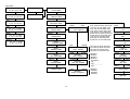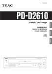
1
Atrie 288LCD
MODEM
User's Manual
288LCD
MODEM
USER'S MANUAL
ATRIE TECHNOLOGY INC.
ATRIE
336/288/144LCD
MODEM
USER'S MANUAL
(Version 4)
Atrie Technology Inc.
10th Floor, No.14, Lane 609, Sec. 5, Chung Hsin Rd.,
San Chung City, Taipei Hsien, Taiwan, R.O.C.
TEL:886-2-2999-5155
FAX:886-2-2999-4960
E-MAIL: [email protected]
(C) Copyright 1999 ATRIE TECHNOLOGY INC.
August 1999
TABLE OF CONTENTS
CHAPTER 1 INTRODUCTION
Overview-----------------------------------------------------------1-1
Modem Features--------------------------------------------------1-2
CHAPTER 2 INSTALLATION
Package Contents--------------------------------------------------2-1
Modem Panel Description-----------------------------------------2-1
Modem Installation-----------------------------------------------2-10
CHAPTER 3 MORE ABOUT THE MODEM
The Modem Mode--------------------------------------------------3-1
The Modem Port and Serial Port--------------------------------3-2
Automatic Speed Matching---------------------------------------3-2
Flow Control-------------------------------------------------------3-4
The Modem Operating Mode-------------------------------------3-6
The ITU-T V.42/V.42bis-------------------------------------------3-7
The GIII Fax Function-------------------------------------------3-10
The Voice Function-----------------------------------------------3-10
CHAPTER 4 AT COMMAND GUIDELINES
Introduction--------------------------------------------------------4-1
Command Syntax--------------------------------------------------4-1
AT Command Summary-------------------------------------------4-1
AT Command Set--------------------------------------------------4-3
MNP10 Command Set--------------------------------------------4-29
CHAPTER 5 REGISTERS
Introduction--------------------------------------------------------5-1
Commands to Change or Read Register-------------------------5-1
I
Register Description-----------------------------------------------5-3
CHAPTER 6 ITU-T V.25BIS OPERATION
Configuration of ITU-T V.25bis----------------------------------6-1
ITU-T V.25bis Command Set--------------------------------------6-1
ITU-T V.25bis Result Code---------------------------------------6-3
HDLC Sync. Operation of ITU-T V.25bis------------------------6-4
CHAPTER 7 DIAL BACK-UP OPERATION
Preparation---------------------------------------------------------7-1
Dial Back-up Operation-------------------------------------------7-1
CHAPTER 8 SPECIAL FUNCTIONS
Connection Security-----------------------------------------------8-1
Call Back Security-------------------------------------------------8-2
Key Lock Security-------------------------------------------------8-4
Remote Configuration---------------------------------------------8-5
APPENDIX A LCD MENU TREE
II
NOTICE
This user's manual is written for both V.34 and V.32bis
standalone models. It is mainly written for the V.34 standalone
modems. There are REMARKs to describe the specified model,
please skip these sections that describe the different models.
The modem optionally provide Voice and AutoSync functions,
there are sections and commands that describe the Voice or
AutoSync functions. If you do NOT purchase these functions,
please skip these sections.
All brand names are registered trademarks of their respective
owners.
CHAPTER 1
INTRODUCTION
Overview
The V.34 modem is a high speed Hayes Compatible DATA/FAX/
VOICE modem which can be used with various types of computers
and terminals. The VOICE function is designed to be optional. It
meets to the BELL 103/212A standards and ITU-T V.21, V.22, V.23,
V.22bis, V.32, V.32bis, V.FC, V.34, V.25bis, V.24, V.25, V.28, V.54,
V.8, V.13, V.42 and V.42bis recommendations and also equips with
the Microcom Networking Protocol (MNP) Class 2 to 5 and 10
services. The modem optionally supports the Hayes AutoSync to
provide synchronous communication capabilities from an
asynchronous terminal or computer. It can be instructed via the
Hayes AT command set to automatically dial or answer calls, and
to perform MNP Class 4/5 services or ITU-T V.42/V.42bis
recommendations. It can also be instructed via ITU-T V.25bis
command to perform auto-dial or auto-answer functions. The
effective throughput of full duplex asynchronous communication
can be up to 115200bps and also the modem can support the
ITU-T V.8, multi-mode handshake recommendation.
It supports two wire full duplex dial up line and two wire full
duplex leased line, four wire full duplex leased line with dial back
up operation. These line types can be activated via AT command,
or front panel LCD controller to perform auto, manual and power
on connect functions. It can meet most application requirements.
The V.34 modem can operate in both the asynchronous and
synchronous modes and provide 100% error-free data transmission
and data compression with auto-dial, redial, auto-answer and
full call progress monitoring functions. Moreover, it supports
dynamic packet size adjustment to ensure optimum data
throughput and MNP10 to ensure the best performance while
1-1
using cellular phone system.
Modem Features
· Compatible with BELL 103, 212A standards and ITU-T V.21,
V.22, V.22bis, V.23, V.32, V.32bis, V.34, V.FC, V.42, V.42bis,
V.24, V.25, V.25bis, V.28, V.54, V.8, V.13 recommendations.
.Provides Hayes AT command set with programmable S registers.
.Provides ITU-T V.25bis auto-answer, auto-dial recommendation.
.User friendly 16*2 characters LCD controller for full functions
control and real time status display.
.Supports ITU-T V.42/V.42bis error correction and data
compression recommendations.
.Supports Microcom Networking Protocol (MNP) Class 4/5 data
compression protocol.
.Provides ITU-T V.8 and Multi-mode handshake according to
ITU-T recommendation.
.Utilizes full duplex asynchronous transmission with a
maximum effective throughput of 115200bps.
.Provides 100% error-free data transmission.
.Supports dynamic packet size adjustment to optimize data
throughput.
.Provides 2 wire full duplex dial up line, 2 wire full duplex
leased line and 4 wire leased line with dial backup operation.
.Asynchronous and synchronous operation selectable on both
front panel LCD controller or AT command.
1-2
.Provides manual dial , manual answer, auto-dial, auto-answer,
redial, and full call progress monitoring functions.
.Provides Microcom Networking Protocol (MNP) Class 10 to
ensure best performance during Cellular Phone communication.
.Supports GIII Fax with EIA Class 1 and Class 2 command and
ITU-T V.17, V.26bis, V.27ter, V.29.
.Optionally provides Voice and AutoSync function.
REMARK: V.32bis Modem Function
The maximum DTE speed can only be up to 57600bps for
V.32bis modem. The maximum DCE speed can only be up to
14400bps for V.32bis modem. And do NOT support the ITU-T
V.8, V.FC, V.34 and MNP10 Recommendations.
1-3
CHAPTER 2
INSTALLATION
Package Contents
Carefully unpack the product package that you have received. The
following is a checklist of the package:
.The modem
.A modem power cable
.Two telephone cables and one terminal box for RJ-45
.Modem manual : 33600/28800/14400bps Modem User's Manual
.Quick reference guide : LCD MENU TREE
If there is any wrong, missing or damaged part, please contact your
dealer.
Modem Panel Description
Modem Front Panel
The standalone modemís front panel contains LCD display, LEDs and
front panel switches, describe below:
TD
RD
MR
TR
CD
AA
<
>
PWR
ENTER
EXIT
Figure 2-1 V.34/V.32bis Modem Front Panel
The standalone modem's front panel contains one 16*2 characters
LCD display, seven LED indicators and four push-button switches
(see Figure 2-1). The LCD display serves to display and configure the
status, LED indicators serve to display the current operating status
and these push button switches serve to configure the LCD controller
2-1
. The following sections describe the functions of the LCD display,
LED indicators and the push-button switches:
LCD Display
There is a 16*2 characters LCD display on the left hand side of the
front panel. This user friendly LCD display shows the status and
configuration informations of the modem. Details on the menu tree
of the LCD display are on Appendix A.
Use the front panel switches and the LCD display to configure or
display the modemís status. All the commands and settings can be
achieved by the LCD controller.
There are three kinds of screens on the LCD display, describe below:
1. Main Screen:
This screen shows the main status of the modem. It contains 9 fields
(see Figure 2-2), describes below:
FIELD2
FIELD3
FIBLD1
FIBLD4
V34 336 A AUTO
M 1152 AS 2L IDL
FIELD5
FIELD9
FIELD6
FIELD8
FIELD7
Figure 2-2 V.34 Main Screen
FIELD2
FIELD3
FIBLD1
FIBLD4
V32B 144 A AUTO
M 576 AS 2L IDL
FIELD5
FIELD9
FIELD6
FIELD8
FIELD7
Figure 2-3 V.32bis Main Screen
2-2
Field 1
The Carrier Field. This field shows the DCE carrier protocol.
The contents of this field are:
Display
Description
V21
ITU-T V.21 300bps
V22
ITU-T V.22 1200bps
V23
ITU-T V.23 1200/75bps
V22B
ITU-T V.22bis 2400bps
V32
ITU-T V.32 9600bps
V32B
ITU-T V.32bis 14400bps
V34
ITU-T V.34 33600bps
B103
BELL 103 300bps
B212
BELL 212A 1200bps
*The V.32bis modem does not support the ITU-T V.34
Recommendation.
Field 2
The DCE Speed Field. This field shows the transmit speed of
the telephone line. The content of this field are:
Display
3
6
12
1275
7512
24
48
72
96
120
144
168
192
216
240
DCE
DCE
DCE
DCE
DCE
DCE
DCE
DCE
DCE
DCE
DCE
DCE
DCE
DCE
DCE
Description
Speed 300bps
Speed 600bps
Speed 1200bps or 1200/75bps
Speed 1200/75bps
Speed 75/1200bps
Speed 2400bps
Speed 4800bps
Speed 7200bps
Speed 9600bps
Speed 12000bps
Speed 14400bps
Speed 16800bps
Speed 19200bps
Speed 21600bps
Speed 24000bps
2-3
288
312
336
DCE Speed 28800bps
DCE Speed 31200bps
DCE Speed 33600bps
*1275 and 7512 are 1200/75bps and 75/1200bps for ITU-T V.23 only.
*The maximum DCE Speed can only be up to 14400bps for V.32bis
modem.
Field 3
The O/A Field. This field shows the originate or answer mode
of the modem. The "O" in this field represents the originate
mode and the "A" represents the answer mode.
Field 4
The Protocol Field. This field shows the error correction and
data compression protocols while connected. The content of
this field is:
Display
AUTO
V42B
LAPM
MNP5
MNP4
MNP10
DIRECT
NORML
The
The
The
The
The
The
The
The
modem
modem
modem
modem
modem
modem
modem
modem
is
is
is
is
is
is
is
is
Description
not connected and set
set to or connected to
set to or connected to
set to or connected to
set to or connected to
set to or connected to
set to or connected to
set to or connected to
to Auto mode
V.42bis
V.42, LAPM
MNP5
MNP4
MNP10
DIRECT mode
NORMAL mode
*The V.32bis modem does not support the MNP10
Recommendation.
Field 5
The Menu Field. This field shows the active motion that the
"ENTER" key been pressed. All the other fields are status
display fields, except this field. Pressing the "LEFT" or
"RIGHT" key will change the content of this field. The content
of this field is:
2-4
Display
M
O
A
D
R
H
Description
Enter Control Menu
Enter Originate Mode
Enter Answer Mode
Enter Dial Mode
Enter Redial Mode
Enter Hangup Mode
Field 6
The DTE Speed Field. This field shows current DTE speed that
is communicating with terminal or computer. The contents of
this field are:
Display
3
6
12
24
48
72
96
120
144
168
192
216
240
264
288
312
336
384
576
768
1152
DTE Speed
300bps
600bps
1200bps
2400bps
4800bps
7200bps
9600bps
12000bps
14400bps
16800bps
19200bps
21600bps
24000bps
26400bps
28800bps
31200bps
33600bps
38400bps
57600bps
76800bps
115200bps
*The maximum DTE speed can only be up to 57600bps for V.32bis
2-5
modem.
Field 7
The Sync./Async. Field. This field shows the synchronous or a
synchronous operation. If the display is "AS", indicates the
modem is operates in asynchronous mode; if "SY", indicates
the modem is in synchronous operation mode.
Field 8
The Line Type Field. This field shows the telephone line type
that the modem is using. The contents of this field are:
Display
2D
2L
4L
DB
Description
2-wire dialup line
2-wire leased line
4-wire leased line
Dial-Backup
Field 9
The Status Field. This field shows the active status of the
modem. The contents of this field are described below:
Display
IDL
TST
CNT
RTN
HNG
RNG
Description
The modem is idle now
The modem is in testing mode
The modem is connecting to remote
modem
The modem is retraining now
The modem is handshaking now
Ring signal is detected by the modem
2. Testing Screen
When entering the diagnostic mode, the modem shows the testing
screen. There are two testing screens, depending on the test pattern.
If you entering the diagnostic mode without test pattern, the testing
screen will be as below:
2-6
<TEST>
LAL
Figure 2-4 Testing Screen
Please use the "EXIT" key to end the test, all the other switches are
ignored during this screen.
If you entering the diagnostic mode with test pattern, the testing
screen will be as below:
AL+U ATTERN
EC:0000 LC:0000
Figure 2-5 Testing Screen
When entering this screen, the modem will display the BIT ERROR
COUNT on the EC field; the LOSS SYNC. COUNT on the LC field. Press
the "LEFT" or "RIGHT" key will insert one error on EC field. Press
the "ENTER" key to reset the EC and LC counter. To end the test,
please press the "EXIT" key.
3. Menu Screen
If the Field 5 of the main screen is in îMî and press the "ENTER" key
, the modem is in the MENU mode, and shows the screen like below:
<MAIN>
Figure 2-6 Protocol Main Menu
Each menu screen controls one or some functions, press the "ENTER"
key to enter that menu and "EXIT" to exit; "LEFT" or "RIGHT" key to
change menu. For detail about menu tree, please refer to
2-7
Appendix A.
LED Indicators
There are seven LED indicator on the front panel. These LED
indicators display the modemís status. It help the user to understand
the status of the modem . The detail functions are described below:
TD (Transmit Data)
Flashes when your local DTE (Data Terminal Equipment)
transmits data into the serial port of the modem.
RD (Receive Data)
Flashes when the local DTE receives data from the modem.
MR (Modem Ready Indicator)
This LED indicator indicates that the modem is ready for
operation. This means that the microprocessor is working.
PWR (Power Indicator)
Lights up when the power is applied to the modem.
TR (Terminal Ready)
Lights up when the modem receive DTR(Data Terminal Ready)
signal, which indicates that the computer or terminal is ready.
CD (Carrier Detected)
Lights up when carrier signal from a remote modem is detected.
AA (Auto Answer)
Lights up when auto answer enabled and flashes on the
condition of receiving ring signal.
Front Panel Switches
There are four switches on the right hand side of the front panel.
These switches are used to configure the LCD controller. It contains
keyboard repeat function in a repeat rate of approximately 6 times
2-8
per second. The functions of the switches are described below:
Left:
This switch scrolls the LCD menu to the left.
Right: This switch scrolls the LCD menu to the right.
ENTER:
This switch is chosen to enter the next level menu. If you are in
the last level menu, you can use this switch to execute the
command or change the setting of the particular configuration.
EXIT:
This switch is chosen to exit to the previous menu. If you are in
the last menu, you can use this switch to abort executing the
command, return to the previous menu or not changing the
setting of the particular configuration. If in the main screen,
press this switch once will display the model and version
information.
Modem Rear Panel
AC
ON
TO DTE
LEASED
LINE
LINE PHONE
OFF
Figure 2-7 Modem Rear Panel (AC power)
ON
FG
DC-48V
TO DTE
LEASED
LINE
LINE PHONE
OFF
Figure 2-8 Modem Rear Panel (DC power)
The modem's rear panel contents one power switch, one power
socket, one serial port (RS-232C) connector, one RJ-45 telephone jack
and two RJ-11 telephone jacks. The following sections briefly describe
2-9
the functions of each part:
Power Switch:
The power switch controls the whole power of the modem. Turn the
switch to "OFF" position will turn off the modem. You can also use
this switch to perform power on reset and initiate the modem using
an ON-OFF-ON transient.
Power Socket (AC):
The power socket is for the power cable that connects the modem to
a power source. The modem comes with an AC power cable. You can
use this power cable to connect the modem to the wall outlet of
power source.
Power Socket (DC):
For the DC power option, there is a terminator on the rear panel.
Please connect the FG to the framing ground of the power source.
Connect the DC -48V to the DC power supply. The input range is
from DC 35V to 73V and the connection is polarity free.
RS-232C Serial Port:
The serial port is a female DB25 connector for the RS-232C cable.
This connects your modem to your local computer or terminal.
Leased Line:
This RJ-45 jack allows user to connect the 2-wire or 4-wire leased
line to the modem. There are 8 contacts inside the RJ-45 connector,
pleased use the pin number 4 and 5 to connect the 2-wire leased
line; use the pin number 4 and 5 to connect the 4-wire transmit pair
and pin number 3 and 6 to connect the 4-wire receive pair.
Line:
This RJ-11 jack allows user to connect the telephone line to the
modem.
2-10
Phone:
This RJ-11 jack allows user to connect a telephone set to the modem.
Modem Installation
Installing Your Modem
1. Look for a location for the modem.
A suitable location for the modem is one that is near the power
outlet and close to the telephone line and your computer. It should
be placed on a sturdy level surface where there is enough space
for unimpeded operation.
2. Check the modem's settings.
You must check the modem carefully to make sure that all the
configurations are in default setting. Please refer to the sections
on this manual for details on the modemís settings.
3. Connect the modem to the telephone line.
The modem has two RJ-11 connectors marked "LINE" and "PHONE".
The connector marked "LINE" is connected to the PSTN telephone
line while the connector marked "PHONE" is connected to the
telephone set. To do this, simply plug the telephone line from the
wall outlet directly into the "LINE" connector on the modem , and
use another telephone cable to connect the telephone set and the
"PHONE" connector.
If you are using the leased line, please connect the leased line to
the jack marked "LEASED LINE". Please refer to the "Modem Rear
Panel" section before for detail connection information.
4. Connect the modem to the computer.
Your modem provides a 25pin RS-232C serial port connector which
2-11
is used to connect the modem to any of the serial ports on your
computer or terminal. Please make sure that the computer or
terminal has been turned off before you connect the modem with
it.
5. Connect the modem to the power source.
Make sure the power switch of the modem is in îOFFî position and
plug the power cable to the power socket of your modem. Plug
the other end of the power cable into the power source.
Installation Check
Turn the power switch to "ON" position. Check the modemís front
panel to determine its current operating state. The front panel LCD
display will show power on self-test screens. If there is no problem
with the installation, the modem will automatically enter the main
menu when you turn on the power with factory default. Press the
"LEFT" or "RIGHT" key, you will find the field 5 changed from M to
D, A, R or H.
Another way to check if your modem has been properly installed is
to use a proper communication software in terminal emulation mode
to input the following commands from your computer or terminal to
the modem:
<Enter>
ATZ <Enter>
If your modem is functioning properly, it will respond with the mess
age "OK". However, If this message fails to appear, turn off your
modem and computer or terminal, and check all the steps detailed in
section "Installing Your Modem". When you are certain that the
modem is correctly installed, repeat the procedure listed above. If the
modem still do NOT response, please contact your dealer.
2-12
CHAPTER 3
MORE ABOUT THE MODEM
This chapter describes a few concept about the modem, the user
should read this chapter carefully to avoid miss understanding or
confusing about the modem's function.
The Modem Mode
The modem has three basic modes: the command mode, data mode
and escape mode. In the command mode you can enter command
to the modem to set registers, parameters and carry out a variety
of dialing and control functions. Details about commands are
given in Chapter 4.
In the data mode, you can transmit and receive data over the
telephone line to another remote modem.
The data mode can be further subdivided into three modes. The
first is the originate mode under which the modem originates a
call; the second is the answer mode, under which the modem
answers the incoming call. The third is the self-diagnostic mode,
under which the transmitted data is looped back through the
modem, allowing evaluation of the modemís performance and line
condition.
When the modem is in data mode, if you issue the escape
character (defined in S register 2) three times with the guard time
(defined in S register 12), the modem will enter escape mode. In
the escape mode, the modem will not drop the line but entering
the command mode. Any characters that coming from the DTE
will be treated as command rather than data and will be executed
after "ENTER" character has been received. But some of the AT
commands can not be executed during the escape mode, such as
ATDn, ATA, AT&Wn etc.
3-1
The Modem Port and Serial Port
Modem port means data link between two modems, serial port
means data link between computer or terminal (DTE) and modem
(DCE). The modem port and serial port of the modem are
independent. There are buffers between modem and serial ports,
so different speeds are possible. The following sections discuss
these related concepts.
Automatic Speed Matching
Automatic speed matching matches the speed of the modem port
to the speed of the remote modem. A connection can be
established between two modems even if the two modems are not
initially set to the same speed. If the remote modem is not capable
of automatic speed matching, a connection may or may not be
established, depending on the speed to which both modems are set
.The connection speed may be determined by the originating or
the answering speed. The resulting connection speed will be
shown on the terminal like below:
CARRIER 33600
PROTOCOL: LAP-M
COMPRESSION: V.42BIS
CONNECT 115200
The CARRIER 33600 means the modem is connecting to a remote
modem in ITU-T V.34, which allows user to transmit or receive
date at 33600bps. The PROTOCOL: LAP-M means the modem has
negotiated with the remote modem and established an ITU-T V.42
connection. The COMPRESSION: V.42BIS indicates that the two
modems are using ITU-T V.42bis to do data compression. Finally,
the CONNECT 115200 shows that the modem is using 115200bps to
communicate with the DTE. These result codes may or may not be
3-2
shown on the terminal screen depending on the setting of the
modem.
The modem supports three methods of automatic speed matching:
1. Multi-mode Handshake
The multi-mode handshake (ATN1) follows the ITU-T multi-mode
handshake recommendation, which can provide full range of speed
to connect to the other modem. That means whatever speed
(protocol) the modem is set to, the modem can connect to BELL
103/212A and ITU-T V.21, V.22, V.23, V.22bis, V.32, V.32bis, V.34
without changing speed.
This feature is convenience for the user to connect to an
unknown modem.
2. ITU-T V.8 Multi-mode Handshake
The modem supports ITU-T V.8 multi-mode handshake. The V.8
will cause the answering modem to send a "ANSam" signal and if
the originate modem is capable of V.8, it response with "CM".
After that both modems will begin a protocol handshake to
determine modulation method, error correction protocol and
whether using celluar connection. When all the condition is
cleared, both modem begin the preselected ITU-T handshake. This
procedure makes the modems connect faster than the old ITU-T
multi-mode handshake.
If the modem can not detect an "ANSam" or "CM" signal from the
remote modem, the modem will abort the ITU-T V.8 handshake
and using other method to connect.
3. Fix-mode Handshake
If you want to connect to the remote modem with a particular
speed, then the fix-mode handshake (ATN0) is useful for you.
Using the fix-mode handshake will cause the modem to use the
DTE speed to make connection. The connection speed will not
3-3
exceed the DTE speed, it can only perform the auto fallback from
V.34 33600bps to V.34 2400bps or V.32bis 14400bps to V.32
4800bps or V.22bis 2400bps to V.22 1200bps.
Another way to determine the connection speed is the S register
37. Setting the S register 37 to a none zero value will cause the
modem to connect to particular speed regardless of the DTE speed
and will also perform the same auto fallback as describes above.
Flow Control
Flow control is the ability to turn on and turn off the flow of
information between transmitting devices. Most computers and
terminals support flow control. However, if the terminal device
does not support flow control, it (flow control) should be disabled
on both the modem port and the terminal serial port. You should
also operate the terminal serial port at the same speed with the
actual connection speed.
The modem can receive and transmit data over the serial port at a
speed different from the modem port. If the serial port operates
at a speed greater than the modem port, the buffer fills to
capacity. If the computer or terminal attached to the serial port of
the modem supports flow control, there is no loss of data when
the buffer fills.
Flow control is achieved by using two methods - software flow
control and hardware flow control.
Software Flow Control
The modem supports two types of software flow control, the first
is the unidirectional flow control and the second is the
bi-directional flow control. In unidirectional software flow control,
only the modem can control the terminalís data flow. Xoff and
Xon characters are sent by the modem to the local or remote
computer. The Xoff character (Determined by S register 33)
signals the local or remote computer to pause the flow of data
while the Xon character (Determined by S register 32) signals the
3-4
local or remote computer to resume the flow of data. The
bi-directional software flow control used Xoff and Xon characters
to control both the modemís and the computerís or terminalís
data flow. Your modem supports software flow control on both
the modem port and the serial port; it also supports hardware
flow control on the serial port.
When flow control is enabled on the modem port, the serial port,
an Xoff character received over the communication lines, causes
the modem port to stop transmitting data from the modem buffer
to the communication lines. If the local device attached to the
serial port continuously sends data, the buffer eventually fills.
When this happens, the modem sends an Xoff character from the
serial port to instruct the local device to stop transmitting data. In
effect, the local device will stop send data and will only restart
sending when it receives an Xon character from the remote
system.
Hardware Flow Control
The modem supports two types of hardware flow control - the
unidirectional and the bi-directional hardware flow control. The
unidirectional hardware flow control is similar to the Xon/Xoff
unidirectional software flow control. It accomplishes flow control
by turning ON and OFF of CTS (Clear-to-Send) signal. When the
CTS signal is turned OFF, the local device will cease to send data
to the serial port of the modem; data transmission will only be
resumed when the CTS signal is turned ON.
Bi-directional flow control uses both the CTS and the RTS
(Request-to-Send). The RTS signal works in the same manner as
the CTS signal, i.e. the modem stops sending data to the serial
port of the local device when the RTS signal is turned OFF, and
resumes sending data only when RTS signal is turned ON. For
most of the applications, the unidirectional hardware flow control
is sufficient. Examples of these applications are systems primarily
involved in downloading files. For applications that need to
support file uploading and do not support Xon/Xoff flow control,
3-5
bi-directional hardware flow control is recommended so that the
local device can also control the flow of data from the modem.
The modem also supports hardware flow control using DTR (DataTerminal-Ready) and DSR (Data-Set-Ready) signal in the RS-232.
The DTR signal works in the same manner with the RTS signal
and the DSR signal works in the same manner with the CTS signal
when setting the modem to do DTR/DSR hardware flow control.
The Modem Operating Mode
The modem operating mode determines how the modem
communicates with the remote modem. The modem operating
modes are: direct mode, normal mode and error correction mode.
These modes are described bellow:
Direct Mode
A direct mode connection is equivalent to any standard V.34
modem connection. In a direct mode connection, the maximum
throughput is equal to the connection rate, and the terminal (DTE)
rate must always match the connection rate. For instance, if the
DTE is set to 33600bps (CARRIER 33600), the throughput will not
exceed 33600bps. On the other hand, if the DTE is set to 33600bps
and the modem falls back to a 9600bps connection (CARRIER
9600), the terminal must be adjusted to operate at 9600bps, and
the throughput will never exceed 9600bps.
The flow control (AT&K) command is ignored when the modem is
set to direct mode. The serial port speed is always adjusted to the
connection speed of the modem port.
Normal Mode
In a normal mode connection, the modem provides data buffers.
This allows the terminal speed to be different from the connection
speed. However, the maximum modem-to-modem throughput
3-6
continues to be equal to the connection rate. For instance, if the
DTE is set to 115200bps and the modem connects at 33600bps
(CARRIER 33600), then as long as the DTE does not overflow the
transmit buffer, data will pass intact, and the terminal speed must
remain at 115200bps. Throughput will not exceed 33600bps.
Since it is difficult to ensure that the DTE will not overflow the
transmit buffer, two methods are provided to indicate to the DTE
whether it can send data to the modem or not. These two methods
are hardware flow control and software flow control. When hard
ware flow control is enables, the RS-232 control line CTS is
controlled by the modem; it indicates to the DTE whether it can
send data or not. When software flow control is enabled, the
modem sends control characters (Xon/Xoff) to the DTE to do flow
control. Conversely, the DTE may also indicate to the modem's
ability to receive data by RTS, an RS-232 control line in hardware
flow control, or by Xon/Xoff software flow control characters.
Error Correction Mode
The modem support ITU-T V.42 error correction protocol. When
configured to V.42, the modem looks for incoming protocol of
V.42 from the remote modem and try to establish an error
correction connection. The modem will provide data buffer so that
the terminal speed may be different from the connection speed. It
also provides error detection and error correction. Flow control
must be activated when in error correction mode.
The ITU-T V.42/V.42bis
The ITU-T V.42 supports two methods of error correction: LAP-M
and, as a fallback, Alternative Protocol (MNP4 compatible). The
modem offers a negotiation technique for determining and
establishing the best method of error correction between two
modems. This technique involves two phases: the detection phase
and the negotiation phase. In the detection phase, which occurs
immediately after the establishment of the modem handshake, the
communicating modems exchange a sequence of detection
3-7
patterns to verify that both modems support the error-correction
technique. In the negotiation phase, which follows the detection
phase, the communicating modem exchange configuration
information to make a best connection. When the modem
originates a call, it will send a detection pattern and wait for the
answering modem to respond. If the answering modem responds,
they will enter the negotiation phase; if the answering modem
does not respond, the originating modem will send the alternative
handshake pattern and try to make the alternative connection.
If the detection phase fails, or negotiation does not achieve the
desired connection type, the modem can hang up, fallback to
alternative protocol (MNP4), or fallback to a standard
asynchronous mode. Desired action to take is selected by S
register 36. Since MNP does not support a detection phase, the
selection of MNP must be made as a force fallback of V.42 with
S register 48 and 36.
S48 - The V.42 Negotiation Action Register
The negotiation process determines the capabilities of the remote
modem. If the capabilities of the remote modem are known and
negotiation is unnecessary, this process can be bypassed if
desires. The following options are selectable using S register 48:
S48=7
Enables negotiation (Factory setting)
S48=0
Disables negotiation; bypass the detection and
negotiation phases; and process with LAP-M.
S48=128
Disables negotiation; bypass the detection and
negotiation phases; and proceed at once with the
fallback actions specified in S register 36. This option
can be used to force the modem to use MNP to
communicate.
S36 - The V.42 Negotiation Fallback
3-8
S register 36 specifies the action to take when the desired
connection cannot be made. The options are:
S36=0 Modem hangs up
S36=1 Modem stays on line and a direct mode connection is
established
S36=3 Modem stays on line and a normal mode connection is
established
S36=4 An MNP connection is attempted; if it fails, the modem
disconnects
S36=5 An MNP connection is attempted; if it fails, a direct
connection is established
S36=7 An MNP connection is attempted; if it fails, a normal
connection is established
These fallback options are initiated immediately on connection if
S register 48=128.
This register can be used with S register 48=128 to set the modem
to MNP mode only. For example:
Modem with S48=128
Function
S36=4
An MNP is attempted; if fails, disconnects.
S36=5
An MNP is attempted; if fails, a direct mode
is made.
S36=6
An MNP is attempted; if fails, a normal
mode is made.
S46 - ata Compression Protocol Selection
3-9
This register selects whether the data compression is effective or
not:
S46=136
Execute the error correction protocol without data
compression.
S46=138
Execute the error correction protocol with data
compression.
The GIII Fax Function
The modem supports the ITU-T V.27ter/V.29 and V.17 for GIII fax.
It uses the EIA Class 1 and Class 2 command for compatibility of
most communication software. It can support from 2400bps to
14400bps GIII Fax speed.
The Voice Function
The modem optionally supports VOICE function. The voice
function include a voice pass-through mode which allows the host
to transmit and receive audio signals. It uses an ADPCM voice
coder and decoder for compression and decompression. It can
compress and decompress voice signals to allow efficient digital
storage of voice messages. Using this voice option with the voice
application software to achieve the voice function such as
answering machine, voice on demand, and voice mail function.
3-10
CHAPTER 4
AT COMMAND GUIDELINES
Introduction
This chapter gives you a detailed explaination of commands
available. The commands include the Hayes AT command set and
some other commands that control extra functions. An
alphabetical listing of commands is listed below:
Command Syntax
The command must be preceded by "AT" (ATtention code) except A
/ and "+++" escape commands. AT can be entered as upper or
lower case characters, and can NOT be deleted by backspace or
delete keys. The attention code is used by the modem to determine
the speed and data format of the incoming data from DTE.
More than one command can be entered in one command line and
may be separated by space for readability. The command line can
NOT exceed 40 characters excluding the attention code and must
be ended by the ASCII character specified by S register 3. The
default of the S register 3 is the decimal 13 -- "Carriage Return". A
line without carriage return will be ignored. Commands following
the AT are processed after receiving the "Carriage Return"
character, and the space added for readability will be ignored.
Any parameters following the AT command that were ignored will
be treated as equal to 0.
AT Command Summary
ATA
A/
ATBn
ATDn
Manual Answer........................................................... 4-4
Repeat Last Command................................................. 4-4
Select ITU-T/BELL Mode........................................... 4-4
Dial............................................................................... 4-4
4-1
ATEn
Echo Command................................................................. 4-6
ATHn
Hang Up the Telephone Line...................................... 4-6
ATIn
Identification Command...............................................
4-6
ATLn
Speaker Volume Control..............................................
4-7
ATMn
Speaker Control..............................................................
4-7
ATNn
Set Multi-or Fix-Mode Handshake............................... 4-7
ATOn
Return to On-Line Mode..............................................
4-8
ATP
Set Pulse Dial..................................................................
4-8
ATQn
Result Code Command..................................................... 4-8
ATSr=n Change the Content of S Register............................... 4-8
ATT
Set Tone Dial...................................................................
4-9
ATVn
Result Code Type............................................................
4-9
ATWn
Negotiation Progress Message Command................... 4-11
ATXn
Extended Result Codes................................................
4-11
ATYn
Long Space Disconnect................................................
4-11
ATZn
Reset.................................................................................
4-12
AT&Cn
Serial Port DCD Control..............................................
4-12
AT&Dn
Serial Port DTR Control..............................................
4-12
AT&Fn
Restore Factory Setting............................................... 4-13
AT&Gn
Select Guard Tone......................................................... 4-13
AT&Kn
Serial Port Flow Control.............................................. 4-13
AT&Ln
Telephone Line Type Select Command........................ 4-14
AT&Mn Asynchronous/Synchronous Mode Selection............. 4-14
AT&Pn
Select Pulse Dial Make/Break Ratio......................... 4-14
AT&Qn
Select Communication Mode....................................... 4-15
AT&Rn
Serial Port RTS Option Command............................... 4-15
AT&Sn
Serial Port DSR Control Command.................................4-15
AT&Tn
Loop Test Functions...................................................... 4-15
AT&Un
Trellis Coding Modulation Selection Command........ 4-16
AT&V
View Profiles and Stored Telephone Number............ 4-16
AT&Wn Store Current Configuration......................................... 4-16
AT&Xn
Select Synchronous Clock Source............................... 4-16
AT&Yn
Power On Profile Selection Command......................... 4-17
AT&Zn=m Store Telephone Number............................................. 4-17
AT%Cn
Data Compression Protocol Selection.......................... 4-17
AT%En
Retrain and Rate Negotiation Command.....................4-18
AT%L
Line Signal Level........................................................... 4-18
AT%Q
Line Signal Quality......................................................
4-18
AT%Rn
Ring Back Message Command.................................... 4-18
AT%S
Secondary Channel Control......................................... 4-19
AT\An
Select Maximum MNP Block Size................................ 4-19
4-2
AT\Bn
AT\F
AT\Gn
AT\Kn
AT\Nn
AT\Rn
AT\S
AT*Kn
AT-En
AT-Rn
AT+MS
+++
AT)Mn
AT*Hn
AT-Kn
AT-Qn
AT@Mn
AT:En
Transmit Break to Remote........................................... 4-19
View Stored Telephone Number.................................. 4-19
Modem Port Flow Control........................................... 4-20
Break Control..............................................................
4-20
Operating Mode..........................................................
4-21
Serial Port Ring Indicator Control................................ 4-21
Modem Status Display.................................................
4-22
Keyboard Interrupt Command...................................... 4-23
ASI Overspeed ........;...............................................
4-23
Serial Port RTS Option................................................
4-24
Select Modulation........................................................
4-24
The Escape Code.........................................................
4-28
Power Level Adjust Command..................................... 4-28
Link Negotiation Speed.................................................. 4-28
MNP Extended Services..............................................
4-29
Enable Fallback to V.22bis/V.22.................................. 4-29
Initial Cellular Power Level Setting............................... 4-29
Compromise Equalizer Enable Command.................... 4-30
AT Command Set
ATA -- Manual Answer
The modem will go off-hook and attempt to answer an incoming
call if correct conditions are met. Upon successful completion of
answer handshake, the modem will go on-line in answer mode.
The modem will enter the connect state after exchanging carrier
with the remote modem. If no carrier is detected within the period
specified in S register 7, the modem hangs up. Any character
entered during the connect sequence will abort the connection
attempt.
ATA/ -- Repeat Last Command
There is no need to type <Return>, after the "/" has typed, the
modem executes the last executed command immediately.
ATBn - Select ITU-T/BELL Mode
When the modem is configured to line speed of 300 or 1200 bps,
4-3
the modem will select BELL or ITU-T modulation according to the
parameter supplied. Any other line speed will use an ITU-T
modulation recommendation.
ATB0 Selects ITU-T recommendation at 300 or 1200 bps during
call establishment and a subsequent connection. (Default)
ATB1 Selects BELL standard at 300 or 1200 bps during call
establishment and a subsequent connection.
ATDn -- Dial
This command directs the modem to go off-hook, dial according to
the string "n" entered and attempt to establish a connection in
originate mode. If no dial string is supplied, the modem will go
off-hook and attempt the handshake in originate mode.
The modem will have up to the period of time specified by S
register 7 to wait for carrier and complete the handshake. If this
time expires before the modem can complete the handshake, the
modem will go on-hook with the "NO CARRIER" response. This
command will be aborted in progress upon receipt of any DTE
character before completion of the handshake, if the AT*K0
command is issued.
Dial Modifies
The valid dial string parameters are described below. Punctuation
characters may be used for clarity, with parentheses, hyphen, and
spaces being ignored.
0-9
*
#
A-D
J
K
L
Dialing digits 0 to 9.
The "star" digit. (tone dialing only)
The "gate" digit. (tone dialing only)
DTMF digits A,B,C, and D.
Perform MNP 10 link negotiation at 1200bps.
(for this call only)
Enable power level adjustment during MNP 10 link
negotiation. (for this call only)
Re-dial last number. The modem will re-dial the last
valid telephone number. The îLî must be immediately
4-4
P
T
R
S=n
!
W
@
&
,
;
after the D with all the following characters ignored.
Select pulse dialing. Pulse dial the numbers that follow
until a "T" is encountered.
Select tone dialing. Tone dial the numbers that follow
until a "P" is encountered.
This command will be accepted, but not acted on.
Dial the number stored in the directory (n = 0 to 9).
(See AT&Zn=m)
Flash, the modem will go on-hook for a time defined
by the value of S register 29.
Wait for dial tone. The modem will wait for dial tone
before dialing the digits following "W". If no dial tone
is detected within the time specified by S register 7, the
modem will abort the rest of the sequence, return on-ho
ok, and generate an error message.
Wait for silence. The modem will wait for at least 5
seconds of silence in the call progress frequency band
before continuing with the next dial string parameter. If
the modem does not detect these 5 seconds of silence
before the expiration of the call abort timer (S register
7), the modem will terminate the call attempt with a
"NO ANSWER" message. If busy detection is enabled,
the modem may terminate the call with the "BUSY"
result code. If answer tone arrives during execution of
this parameter, the modem handshakes.
Wait for AT&T îbongî tone for credit card dialing
before continuing with the dial string. If bong is not
detected within the time specified by S register 7, the
modem will abort the rest of the sequence, return on-ho
ok, and generate an error message.
Dial pause. The modem will pause for a time specified
by S register 8 before dialing the digits following ",".
Return to command state. Added to the end of a dial
string, this causes the modem to return to the command
state after it processes the portion of the dial string
preceding the ";". This allows the user to issue
additional AT commands may be placed in the original
command line following the ";" and/or may be entered
on subsequent command lines. The modem will enter
call progress only after an additional dial command is
4-5
^
issued without the ";" terminator. Use ATH0 to abort the
dial in progress, and go back on-hook.
Enable calling tone. Applicable to current dial attempt
only.
ATEn -- Echo Command
The modem enables or disables the echo of characters to the
DTE according to the parameter supplied.
ATE0
ATE1
Disables command echo
Enables command echo (Default)
ATHn -- Hang Up the Telephone Line
ATH0
ATH1
Directs the modem to disconnect the remote modem
and hang-up (Default)
Causes the modem to go off-hook.
ATIn -- Identification Command
ATI0
ATI1
ATI2
ATI3
Reports product code "33600".
Reports a pre computed checksum, in the format of
"CheckSum: XXX".
Performs the calculation of ROM checksum and
check with the pre computed checksum. If correct,
reports "OK"; if not
reports "ERROR".
Reports firmware revision in the format of "33600
Version SA X.X".
Returns the identification code and checksum result of the modem.
REMARK: V.32bis Modem Function
For the V.32bis modem, it reports "14400" when ATI0
command is received. It reports "14400 Version SB X.X"
when ATI3 command is received.
ATLn -- Speaker Volume Control
4-6
The modem uses software volume control to avoid poor contact of
the volume VR. The volume is divided into 3 steps, described
below:
ATL0/L1
ATL2
ATL3
Low speaker volume (Default)
Medium speaker volume
High speaker volume
ATMn -- Speaker Control
ATM0
ATM1
ATM2
ATM3
Speaker always off
Speaker on until the modem receives a carrier (Default)
Speaker always on
Speaker off while dialing, then on until the modem
receives a carrier
Controls the speaker. Immediately takes effect upon execution.
ATNn -- Set Multi- or Fix- Mode Handshake
ATN0
ATN1
ATN2
ATN3
Fix-mode handshake. The connection speed depends on
the DTE speed or S register 37 speed. It can NOT
connect with higher speed modem. The remote modem
must have the ability to fall back if using higher speed
than your modem.
Multi-mode handshake. Follows the recommendation of
ITU-T multi-mode handshake. It can automatically
change the connection speed to make most efficient
connection. (Default)
Reserved
Same as ATN1 but without V.23 mode.
This command controls the handshake method of the modem.
When the modem is set to answer mode, it usually sets to multimode handshake (ATN1) to get the most effective connection. If
the remote modemís speed is known, you can set the modem to
fix-mode handshake and adjust the DTE speed to meet the remote
modem's speed to reduce the time needed for handshake.
ATOn -- Return to On-Line Mode
4-7
This command determines how the modem will enter the on-line
data mode. If the modem is in the escape (on-line command) mode,
whether enters the on-line data mode with or without retrain. If
the modem is in the off-line command mode (not connected), an
"ERROR" message is reported.
ATO0
ATO1
Enters on-line data mode without a retrain. Generally,
if a connection exists, this command connects the DTE
back to the remote modem after an escape (+++).
Enters on-line data mode with a retrain before
returning to on-line data mode.
ATP -- Set Pulse Dial
Directs the modem to use pulse dialing. This command can be used
as AT command or dial modifier of the ATD command.
ATQn -- Result Code Command
ATQ0
ATQ1
Sends result codes to the local system. (Default)
Prohibits the modem from sending result codes to
the local system.
Some of the central site computers do not recognize the result
code of the modem, please use the ATQ1 command to disable the
result code of the modem.
ATSr=n -- Change The Content of S Register
ATSr=n
ATSr
AT?
AT=n
" r " indicates the number of S register.
" n " indicates the content of S register.
Select S register
Read pre-selected S register
Change the content of pre-selected S register to n.
This command can change the content of S register. The content, n
, should be in decimal form.
ATSr?
Read the content of S register r
4-8
This command causes the modem to return a 3 digits decimal
number indicates the content of the specified S register. The
rindicates the number of the S register.
ATT -- Set Tone Dial
Directs the modem to use tone dialing. This command can be used
as AT command or dial modifier of the ATD command.
ATVn -- Result Code Type
ATV0
ATV1
Selects short (digit) form result codes.
Selects long (verbose) form result codes. (Default)
The command result code is reported in two ways. The first is the
long form, is reported in verbose type result code. This is easy to
read for user. The second is the short form, is reported in
numeric digit form. This is usefull for the software programmer to
identify result codes during program application.
The result code is also devided into standard and extended result
codes. The standard result code is reported while the ATX0
command is issued. The extended resulted code is reported while
other ATXn parameter is issued. Some other result codes are
reported upon ATW1 command issued. The detail result codes are
listed below:
Short Form
0
1
2
3
4
5
6
7
8
9
10
11
12
Long Form
OK
CONNECT
RING
NO CARRIER
ERROR
CONNECT 1200
NO DIALTONE
BUSY
NO ANSWER
CONNECT 0600
CONNECT 2400
CONNECT 4800
CONNECT 9600
Standard
*
*
*
*
*
Extended
*
*
*
*
*
*
*
*
4-9
13
14
15
16
17
18
19
22
23
40
44
45
46
47
48
49
50
51
52
53
54
55
56
57
58
59
61
62
63
64
66
67
69
70
77
80
81
+F4
CONNECT 7200
CONNECT 12000
CONNECT 14400
CONNECT 19200
CONNECT 38400
CONNECT 57600
CONNECT 115200
CONNECT 1200TX/75RX
CONNECT 75TX/1200RX
CARRIER 300
CARRIER 1200/75
CARRIER 75/1200
CARRIER 1200
CARRIER 2400
CARRIER 4800
CARRIER 7200
CARRIER 9600
CARRIER 12000
CARRIER 14400
CARRIER 16800
CARRIER 19200
CARRIRE 21600
CARRIER 24000
CARRIER 26400
CARRIER 28800
CONNECT 16800
CONNECT 21600
CONNECT 24000
CONNECT 26400
CONNECT 28800
COMPRESSION: CLASS 5
COMPRESSION: V.42 bis
COMPRESSION: NONE
PROTOCOL: NONE
PROTOCOL: LAPM
PROTOCOL: ALT
PROTOCOL: ALT-CELLULAR
+FCERROR
*
*
*
*
*
*
*
*
*
*
*
*
*
*
*
*
*
*
*
*
*
*
*
*
*
*
*
*
*
*
*
*
*
*
*
*
*
*
ATWn -- Negotiation Progress Message Command
This command controls the format of CONNECT messages.
ATW0
Upon connection, the modem reports only the DTE
4-10
ATW1
ATW2
speed (e.g., CONNECT 57600). Subsequent responses are
disabled. (Default)
Upon connection, the modem reports the line speed, the
error correction protocol, and the DTE speed,
respectively. Subsequent responses are disabled.
Upon connection, the modem reports the DCE speed
(e.g.,CONNECT 14400). Subsequent responses are disabled.
ATXn -- Extended Result Codes
ATX0
ATX1
ATX2
ATX3
ATX4
The modem ignores dialtone and busy tone when
dialing. Sends standard result codes when a connection
is completed regardless of connection speed.
The modem ignores dialtone and busy tone. Sends
extended result codes when a connection is made.
The modem ignores busy tone. Sends "NO DIALTONE"
if no dialtone is detected in 5 seconds of a dial attempt.
Sends extended result codes when a connection is
made.
The modem ignores dial tone. Sends "BUSY" if busy
tone is detected. Sends extended result codes when a
connection is made.
The modem sends "NO DIALTONE" if no dialtone is
detected in 5 seconds of a dial attempt. Sends "BUSY"
if busy tone is detected. Sends extended result codes
when a connection is made. (Default)
ATYn -- Long Space Disconnect
This command sets the modem whether to disconnect when a
space of 1.6 seconds or more is received from the remote modem or
not.
ATY0
ATY1
Disables the long space disconnect feature (Default)
Enables the long space disconnect feature
ATZn -- Reset
The reset command performs the following:
4-11
1. Disconnects the telephone line.
2. Performs self-test diagnostics.
3. Clears the modem and serial port buffer.
4. Restores the profiles that stored in NVRAM.
5. Reads configuration switches.
6. Enters the command mode.
The ATZ command can also select the profile 0 to 3 to recall. Key
in ATZ or ATZ0 will cause the modem to recall profile 0, ATZ1
will cause the modem to recall profile 1.
ATZ0
ATZ1
ATZ2
ATZ3
Recall
Recall
Recall
Recall
profile
profile
profile
profile
0
1
2
3
AT&Cn -- Serial Port DCD Control
AT&C0
AT&C1
AT&C2
Sets CD always ON
Sets CD to follow the state of carrier (Default)
Sets CD ON except during disconnect (3~5 sec.)
Controls the CD signal of the serial port. Use this command to
achieve special effects to meet the need of central site computers.
AT&Dn -- Serial Port DTR Control
AT&D0
AT&D1
AT&D2
AT&D3
Assumes DTR ON.
Enters command mode on detecting ON-to-OFF
transition of DTR.
Goes ON-HOOK on detecting ON-to-OFF transition of
DTR. (Default)
Resets the modem on detecting ON-to-OFF transition of
DTR.
Controls the action on detecting the ON-to-OFF transition of DTR.
You can use this command to meet the special requirements for
terminals or computers.
4-12
AT&Fn -- Restore Factory Setting
The factory default setting is stored on the EPROM; whatever the
modem sets, you can always return to default setting by this
command.
PROFILE
0
MODEM SPEED V.34/33.6k
PROTOCOL
AUTO
DTE SPEED
115200
DATA FORMAT
ASYNC
LINE TYPE
2D
ORG/ANS
ORG
FLOW CTRL
RTS/CTS
DTR OPTION
&D2
COMMAND
AT
1
2
3
4
5
6
7
8
9
V.32/9.6k V.32/9.6k V.34/19.2k V.34/19.2k V.32b/14.4k V.32b/14.4k V.32/9.6k V.32/9.6k V.22b/2.4k
DIRECT
DIRECT
AUTO
DIRECT
AUTO
DIRECT
DIRECT
DIRECT
DIRECT
9600
9600
19200
19200
14400
14400
9600
9600
2400
ASYNC.
SYNC.
ASYNC.
SYNC.
ASYNC.
SYNC.
ASYNC.
SYNC.
ASYNC.
2D
2D
2L
4L
2L
4L
2L
4L
2L
ORG
ORG
ORG
ORG
ORG
ORG
ORG
ORG
ORG
OFF
OFF
RTS/CTS
OFF
CTS/RTS
OFF
OFF
OFF
OFF
&D2
&D2
&D0
&D0
&D0
&D0
&D0
&D0
&D0
AT
V.25BIS
DUMB
DUMB
DUMB
DUMB
DUMB
DUMB
DUMB
AT&Gn -- Select Guard Tone
AT&G0
AT&G2
Disables guard tone (Default)
Selects 1800 Hz guard tone
AT&Kn -- Serial Port Flow Control
AT&K0
AT&K1
AT&K2
AT&K3
AT&K4
AT&K5
AT&K6
AT&K7
AT&K8
Disables local flow control.
Enables unidirectional RTS/CTS hardware flow
control.
Enables unidirectional XON/XOFF software flow
control.
Enables bi-directional RTS/CTS hardware flow
control. (Default)
Enables bi-directional XON/XOFF software flow
control.
Enables transparent XON/XOFF software flow
control.
Enables both RTS/CTS and XON/XOFF flow control.
(Default for fax mode)
Enables bi-directional DTR/DSR hardware flow control.
Enables unidirectional DTR/DSR hardware flow control.
This command controls the type of flow control between the
modem and the serial port of the computer or terminal. When the
modem connects to the remote modem using normal mode, or error
4-13
correction mode, the data flow between the modem and the serial
port should be controlled by flow control to avoid data loss. If the
modem connects to remote modem using direct mode, this
command will be ignored. Please refer to Chapter 3 for detail of
flow control.
AT&Ln -- Telephone Line Type Select Command
AT&L0
AT&L1
AT&L2
Disables leased line operation, enables PSTN operation.
(Default)
Enables 2-wire leased line operation, disables PSTN
operation.
Enables 4- wire leased line operation, disables PSTN
operation.
AT&Mn -- Asynchronous/Synchronous Mode
Selection
This command determines the asynchronous or synchronous
operating mode. The modem treats the &M command as subset of
the &Q command.
AT&M0
AT&M1
AT&M2
AT&M3
Selects direct asynchronous operation. (Default)
Selects synchronous data mode with Async. off-line
command mode.
Selects synchronous data mode with Async. off-line
command mode. Same as &M1 except that &M2
enables DTR dialing of stored telephone number at
location 0. The modem will disconnect if DTR is OFF for
more than the time period in S register 25 (in units of
hundredths of a second); the data connection will be
synchronous.
Selects synchronous data mode. This mode allows
DTR to act as Voice/Data switch. The call is terminated
while DTR is inactive. When DTR becomes actives, the
handshake proceeds in originate or answer mode
according to the front panel LCDís setting.
**The modem disables the MNP and V.42bis functions
automatically when you select synchronous mode.
4-14
AT&Pn -- Select Pulse Dial Make/Break Ratio
This command determines the Make/Break ratio used during pulse
dialing. It has no effect in tone dialing.
AT&P0
AT&P1
AT&P2
AT&P3
Selects 39%-61% Make/Break ratio at 10 pulses per
second.(Default)
Selects 33%-67% Make/Break ratio at 10 pulses per
second.
Selects 39%-61% Make/Break ratio at 20 pulses per
second.
Selects 33%-67% Make/Break ratio at 20 pulses per
second.
AT&Qn -- Select Communication Mode
This command selects synchronous or asynchronous, error
control or normal mode operation.
AT&Q0
AT&Q1
AT&Q2
AT&Q3
AT&Q5
AT&Q6
Communicates in asynchronous mode.
Communicates in synchronous mode 1 -- Async.to-Sync.
Communicates in synchronous mode 2 -- stored
number dial.
Communicates in synchronous mode 3 -- voice/data
switch.
Communicates in error correction mode.
(Default)
Communicates in asynchronous mode with automatic
speed buffering -- for interfaces requiring constant
speed between the DTE and DCE.
AT&Rn -- Serial Port RTS/CTS Option Command
AT&R0
AT&R1
CTS follows RTS at all time (Default)
Assumes CTS always on
This command selects the CTS option of the serial port. Some of
4-15
the DTE need to set different options, you can select AT&R0 or AT
&R1 according to the specification of DTE. This command effects
only in synchronous mode and asynchronous direct mode. In V.25
bis operation, the CTS acts according to V.25bis recommendation.
AT&Sn -- Serial Port DSR Control Command
AT&S0
AT&S1
AT&S2
DSR remains ON at all time (Default)
DSR follows the ITU-T recommendation
DSR follows carrier
AT&Tn -- Loop Test Functions
AT&T0
AT&T1
AT&T3
AT&T4
AT&T5
AT&T6
AT&T7
AT&T8
Ends loop test
Local analog loop back
Local digital loop back
Responds to remote digital loop back request (Default)
Ignores remote digital loop back request.
Initiates ITU-T remote digital loop back
Remote digital loop back with self-test
Local analog loop back with self-test
AT&Un -- Trellis Coding Modulation Selection
Command
This command selects whether to use trellis coding modulation or
not. Using trellis coding modulation will provide up to 4 dB of
extra noise immunity improve data reliability in V.32 mode. Both
the local and remote modem should be set to enable to ensure
trellis coding modulation takes place.
AT&U0
AT&U1
Enables trellis coding modulation (Default)
Disables trellis coding modulation
AT&V -- View Profiles and Stored Telephone Number
This command shows the active configuration, and four user
profiles.
4-16
AT&Wn -- Store Current Configuration
AT&W0
AT&W1
AT&W2
AT&W3
Saves current configuration
commands and registers.
Saves current configuration
commands and registers.
Saves current configuration
commands and registers.
Saves current configuration
commands and registers.
at user profile 0, including
at user profile 1, including
at user profile 2, including
at user profile 3, including
AT&Xn -- Select Synchronous Clock Source
Selects the source of the transmit clock for the synchronous mode
operation.
In asynchronous mode, the transmit and receive clocks are turned
OFF. In synchronous mode, the clocks are turned ON with the
frequency of 1200 Hz or faster corresponding to the speed that is
selected for modem operation.
AT&X0
AT&X1
AT&X2
Selects internal clock. The modem generates the
transmit clock signal and applies it to the TXCLK
output at the serial interface. (Default)
Selects external clock. The local DTE causes the
transmit clock signal on the XTCLK input of the serial
interface. The modem applies this clock to the TXCLK
output at the serial interface.
Selects slave receive clock. The modem drives the
transmit clock signal from the incoming carrier and
applies it to the TXCLK output at the serial interface.
AT&Yn -- Power On Profile Selection Command
This command selects the prestored profile 0 to 3 to recall when
turn ON the power of the modem. This command has NO effect
when issuing the ATZ command, the user should use the ATZ0
to ATZ3 to recall profile when software reset.
AT&Y0
Recalls profile 0 when power on (Default)
4-17
AT&Y1
AT&Y2
AT&Y3
Recalls profile 1 when power on
Recalls profile 2 when power on
Recalls profile 3 when power on
AT&Zn = m -- Store Telephone Number
AT&Zn = m The "n" indicates the telephone number locations,
is valid within 0 to 9. The "m" is a dial string of up
to 23 characters. Valid dial string characters are 0
to 9, dial modifiers and for tone dialing #, *. Modem
will ignore invalid characters and truncate dial
strings longer than 23 characters. This
command must be the last one on a command line.
AT%Cn -- Data Compression Protocol Selection
This command enables or disables data compression negotiation.
The modem can only perform data compression on an error
correction link.
AT%C0
AT%C1
AT%C2
AT%C3
Disables data compression
Enables MNP5 error correction
Enables V.42bis data compression
Enables both MNP5 and V.42bis data compression
(Default)
AT%En -- Retrain and Rate Negotiation Command
AT%E0
AT%E1
AT%E2
Disables auto retrain feature
Enables auto retrain feature
Enables auto retrain and rate negotiation with
fall back/forward feature (Default)
The AT%En command controls the auto retrain and rate
negotiation features of the modem. Auto retrain enables the
modem to monitor the line quality and request a retrain if the line
quality is too poor. Rate negotiation feature enables the modem to
change the line speed during the V.34, V.32bis or V.32 retrain
sequence according to the line quality. If retrain is encountered,
the modem will stop the data flow for a shot period of time.
4-18
AT%L -- Line Signal Level
Returns a value which indicates the received signal level. The
value returned is a direct indication at the telephone line connector
. For example, 009 = -9 dBm, 043 = -43 dBm, and so on.
AT%Q -- Line Signal Quality
Reports the line signal quality. The line quality shows the line
noise, the distortion and the frequency shift of the telephone
network. Based on the line quality, retrain or fall back/fall forward
may be initiated if enabled by AT%E1 or AT%E2.
The line quality is reported in three decimal digits. The modem will
return "ERROR" if not connected to the remote modem.
AT%Rn -- Ring Back Message Command
AT%R0
AT%R1
Disables ring back message (Default).
Enables ring back message
If issues the AT%R1 command, the modem will return the "RING
BACK" or "102"(depending on the ATVn command) message to
indicate the ring back signal.
AT%S -- Secondary Channel Control
This command controls the On/Off of the Secondary Channel. You
have to turn on the Secondary Channel to achieve the Connection
security and the Remote configuration of the modem.
AT%S0
AT%S1
Disables Secondary Channel (Default)
Enables Secondary Channel
AT\An -- Select Maximum MNP Block Size
The modem will operate an MNP error correction link using a
4-19
maximum block size controlled by the parameter supplied.
AT\A0
AT\A1
AT\A2
AT\A3
The maximum
The maximum
The maximum
(Default)
The maximum
MNP block size to be 64 characters
MNP block size to be 128 characters
MNP block size to be 192 characters
MNP block size to be 256 characters
AT\Bn -- Transmit Break to Remote
In non-error correction mode, the modem will transmit a break
signal to the remote modem with a length in multiples of 100 ms
according to parameter n specified. If a number in excess of 9 is
entered, 9 is used. The command works in conjunction with the
S register 82.
In error correction mode, the modem will signal a break through
the active error correction protocol, giving no indication of the
length. The modem will return a "NO CARRIER" result code if not
connected.
Note: When the modem receives a break from the remote modem,
break is passed to the DTE as follows: In direct mode , the
break length is passed; in normal mode and in error
correction mode, a 300 ms break is passed.
AT\F -- View Stored Telephone Number
This command shows the content of the ten stored telephone
numbers.
AT\Gn -- Modem Port Flow Control
AT\G0
AT\G1
Disables modem port flow control (Default)
Enables modem port flow control
If enables the modem port flow control, the modem will use the
XON/ XOFF characters to do the flow control. This command only
valids when the modem is in normal mode, has no effect during
4-20
error correction or direct mode connection.
AT\Kn--Break Control
Controls the response of the modem to a break received from the
DTE or the remote modem or the \B command according to the
parameter supplied. The default of this command is AT\K5. The
response is different in three separate states, describe below:
Break received
\Bn command
from DTE while in received from DTE
connect state
while in on line
during on line
command state
mode
\K0
\K1
Enter on line
command mode, no
break sent to the
remote modem
Clear data buffers
and send break to
remote modem
\K2
Same as 0
\K3
Immediately send
break to remote
modem
Same as 0
\K4
\K5
Send break to
remote modem in
sequence with
transmitted data.
Purge buffers,
immediately send
break to remote
modem
Purge buffers,
immediately send
break to remote
modem
Immediately send
break to remote
modem
Immediately send
break to remote
modem
Send break to
remote modem with
data
Send break to
remote modem with
data
4-21
Break received
from remote
modem while in
connect state
during non error
corrected
connection
Purge buffers,
immediately send
break to DTE
Purge buffers,
immediately send
break to DTE
Immediately send
break to DTE
Immediately send
break to DTE
Send break to DTE
in sequence with
data
Send break to DTE
in sequence with
data
AT\Nn -- Operating Mode
This command controls the preferred error correcting mode to be
negotiated in a subsequent data connection. This command has the
similar function with the S register 36 and 48 and AT&Qn
command. Changing this command will affect these registers and
command's content.
AT\N0
AT\N1
AT\N2
AT\N3
AT\N4
AT\N5
selects normal speed buffered mode (disables errorcorrection mode)
Selects direct mode and is equivalent to &M0, &Q0
mode of operation (Forces &Q0)
Selects reliable (error-correction) mode. The modem will
first attempt a LAP-M connection and then an MNP
connection. Failure to make a reliable connection results
in the modem hanging up (Forces &Q5, S36=4, and
S48=7)
Selects auto reliable mode. This operates the same
as \N2 except failure to make a reliable connection
results in the modem falling back to the speed buffered
normal mode (Forces &Q5, S36=7, and S48=7) (Default)
Selects LAP-M error-correction mode. Failure to make
a LAP-M error-correction results in the modem
hanging up. (Forces &Q5 and S48=0)
Note: The AT-K1 command can override the AT\N4
command.
Selects MNP error-correction mode. Failure to make an
MNP error-correction connection results in the modem 3
hanging up. (Forces &Q5, S36=4 and S48=128)
AT\Rn -- Serial Port Ring Indicator Control
AT\R0
AT\R1
Keeps the ring indicator ON for the duration of the
telephone call
Turns OFF the ring indicator after the telephone call is
answered (Default)
This command controls the RS-232C pin No.22 (ITU-T V.24 No.125
signal, Calling Indicator). You can set this pin to always ON or ON
until answered during the telephone call.
4-22
AT\S -- Modem Status Display
This command displays the active command setting and lists the
command. The following is an example of the screen display when
the AT\S command is issued:
AT+MS Report:11,1,2400,33600
Protocol :11 (V.34)
Mode
:1 (Auto with V.8)
Min. Speed: 2400
Max. Speed: 33600
DTE SPEED: 115200 bps, DATA BITS: 8 PARITY: NONE STOP BIT: 1
DCE SPEED: Idle
LINK LAYER PROTOCOL: Idle
COMPRESSION: Idle
LAST DIAL NUMBER=T 886 2 999-5155
CMD
===
B1
L1
DESCRIPTION
===========
BELL OR ITU-T........
SPK VOLUME..........
OPTION
CMD
DESCRIPTION
====== ==== ===========
...............Bell E1
COMMAND ECHO....
...............Low M1
SPK MODE.................
OPTION
==========
..................On
...........Mode 1
Press ESC to stop or press ANY KEY to continue.......
CMD
===
N1
Q0
W0
Y0
&D2
&K3
&P0
&R0
&T4
&X0
%A1
%E2
%Q
%S0
\G0
\R1
*E0
DESCRIPTION
OPTION
CMD
===========
======= ===
MULTI MODE................
.....................On T
QUIET MODE.................
....................Off V1
EC REPORT OPTION....
...................DTE X4
LONG SPACE DISC......
....................Off &C1
DTR OPTION.................
............Onhook &G0
FLOW CONTROL..........
..........RTS/CTS &L0
PULSE RATE................
39%-61% 10pps &Q5
RTS/CTS........................
.......Follow RTS &S0
RDL OPTION................
.. ALLOW RDL &U0
SYNC CLOCK...............
..............Internal &Y0
Asym. SPD ON/OFF....
.........................On %C3
AUTO RETRAIN...........
..Enable+FF/FB %L
LINE QUALITY............
....................Idle %R0
2nd CHANNEL..............
......................Off \A2
MODEM FLOW CNTRL.. ......................Off \L1
RI OPTION......................
......Follow ring )M0
CALLBAK SECURITYÖ
......................Off *H0
DESCRIPTION
===========
DIAL MODE...................
VERBOSE MODE..........
RESULT CODE TYPE..
DCD OPTION.................
GUARD TONE...............
LINE MODE...................
CONNECT MODE..........
DSR OPTION.................
V.32 9600 TCM............
POWER ON PROFILE.
COMPRESSION.............
LINE LEVEL.................
RINGBACK OPTION....
MNP BLOCK SIZE.......
MNP BLOCK XFER.....
MNP10 PWR ADJUST.
MNP10 LINK SPEED....
Press ESC to stop or press ANY KEY to continue.......
4-23
OPTION
========
............Tone dial
.........................On
................Mode 4
........Follow carr
........................Off
....................PSTN
.....Error Correct
..........Always on
.........................On
.............Profile 0
.......Enable Both
........................Idle
........................Off
........................192
.................Mode 1
........................Off
..............Hightest
CMD
===
*K0
-R0
@M18
S000
S002
S004
S006
S008
S010
S012
S020
S025
S029
S032
S037
S046
S082
DESCRIPTION
===========
KEY INTERRUPT..........
RTS OPTION..................
MNP10 XMIT LEVEL...
RINGS TO ANSWER....
ESCAPE CHAR..............
<LF> CHAR.................
WAIT DIAL TONE........
PAUSE TIME.................
CARRIER LOS DISC......
ESC GUARD TIMER.....
AUTOSYNC CHAR.......
DELAY TO DTR OFF...
FLASH DIAL TIMER...
XON CHAR....................
LINE CONNECT SPD....
COMPRESS CONTROL..
BREAK CONTROL.........
OPTION
CMD
======= ===
...................On -K0
.............Normal -Q1
...........-18 dbm :E1
...................001 S001
...................043 S003
...................010 S005
...................002 S007
...................002 S009
...................014 S011
...................050 S018
...................000 S024
...................005 S026
...................040 S030
...................017 S033
...................000 S038
....................138 S048
....................128 S086
DESCRIPTION
============
MNP10 EXT SERVE.......
MNP10 FBACK 2400.....
COMPROM EQULIZER...
RING COUNTER.............
<CR> CHAR.................
<BS> CHAR..................
WAIT CARRIER.............
CARRIER RESPONSE...
DTMF DURATION........
TEST TIMER.................
SLEEP INACT..............
RTS TO CTS DELAY...
CONNECT INACT.........
XOFF CHAR..................
HANGUP DELAY.........
V42 NEGO. CONTROL...
CALL FAILURE COD....
OPTION
========
.....................Off
......................On
......................On
...................000
.....................013
....................008
...................045
...................006
...................095
...................000
...................000
....................001
...................000
....................019
....................005
....................007
....................000
Press ESC to stop or press ANY KEY to continue.......
CMD
===
S091
S099
S212
DESCRIPTION
===========
PSTN XMIT LEVEL.....
L.L XMIT LEVEL.........
BACKUP TIMER..........
OPTION
=======
...................010
.................010
.................060
CMD
DESCRIPTION
=== ============
S092 FAX XMIT LEVEL.........
S211 RESTORE TIMER...........
OPTION
========
.......................010
......................060
OK
AT*Kn -- Keyboard Interrupt Command
AT*K0
AT*K1
Enables keyboard interrupt during handshake (Default)
Disables keyboard interrupt during handshake
This command controls the keyboard interrupt function. After the
modem enters the waiting for handshake state, if any character
coming from the terminal to the modem before the handshake has
finished, the modem will drop the telephone line and return the
"NO CARRIER" result code. If your system will send characters
during the handshake sequence, please use this command to
disable the keyboard interrupt. This command controls only in AT
command mode. If you set the modem to power on operation, V.25
bis or dumb mode, the modem will ignore AT*Kn command and
act as disable keyboard interrupt.
AT-En - Asynchronous to Synchronous Interface
This command can only be used in Asynchronous direct mode. If
set in Asynchronous direct mode and cannot connect to remote
4-24
modem, please set to standard range (-E1).
AT-E0/-E1 Speed drift in expandsion mode.
Speed range: +2.3% ~ -2.5% (Default)
AT-E1
Speed drift in standard mode.
Speed range: +1% ~ -2.5%
AT-Rn--Serial Port RTS Option
AT-R0
AT-R1
Ignore RTS signal
RTS action follows RS-232 definition (Default)
This command controls the RTS option of the serial port. You can
select the options according to the requirement of DTE.
AT+MS - Select Modulation
This extended-format command selects the modulation, optionally
enables or disables automode, and optionally specifies the lowest
and highest connection rates using one to four subparameters. The
command format is:
AT+MS=<mod>[,[<automode>][,[<min_rate>][,[<max_rate>]]]]
<ENTER>
Notes:
1. For 14400 bps and lower speeds, the ATNn command and S
register 37 can alternatively be used, in which case the AT+
Ms sub parameters will be modified to reflect the ATNn and
S37= x setting. Use of the ATNn and S37=x commands is not
recommended but it is provided for compatibility with existing
communication software. (S register 37 is not updated by the
AT+Ms command)
2. Sub parameters can be not entered (enter a comma only or
<ENTER> to skip the last sub parameter) but remain at their
4-25
current values.
Reporting Selected Options
The modem can send a string of information to the DTE consisting
of selected options using the following command:
AT+MS?
The response is:
<mod>,<automode>,<min_rate>,<max_rate>
For example:
11,1,300,28800
Reporting Supported Options
The modem can send a string of information to the DTE consisting
of supported options using the following command:
AT+MS=?
The response is:
(list of supported <mod> values), (list of supported <
automode> values), (list of supported <min_rate> values),
(list of supported <max_rate> values)
For example:
(0,1,2,3,9,10,11,64,69,74), (0,1), (300-28800), (300-28800)
Sub Parameter Definitions
1. <mod>= A decimal number which specifies the preferred
modulation (automode enabled) or modulation (automode
disabled) to use in originating or answering a connection.
The options are:
<mod> Modulation
Possible Rates (bps)
------- ---------------------------------------------------0
V.21
300
4-26
Notes
-----------
1
2
3
9
10
11
V.22
V.22 bis
V.23
V.32
V32 bis
V.34
64
69
74
Bell 103
Bell 212
V.FC
1200
2400 or 1200
1200
9600 or 4800
14400, 12000, 9600, 7200, or 4800
33600, 31200, 28800, 26400, 24000,
21600,19200, 16800,14400, 12000,
9600, 7200, 4800, or 2400
300
1200
28800, 26400, 24000, 21600, 19200,
16800,or 14400
(Default)
The modem may also automatically switch to another modulation
(automode), subject to the following constraints:
a. There is no standard way to switch from Bell to ITU-T in
automode.
b. The DTE may disable automode operation. (see <
automode> below)
c.
The DTE may constrain the range of modulations
available .by specifying the lowest and highest rates.
(see <min_rate > and <max_rate> below)
2. <automode> is an optional numeric value which enables or
disables automatic modulation negotiation using ITU-T V.8 or
ITU-T multi- mode handshake. The options are:
<automode>
---------------0
1
Option Selected
-------------------------------------------Automode disabled
Automode enabled using V.8 or multi-mode
Notes
--------Default
The default value is 1, which enables automode. Note, however,
there are modulations for which there is no automatic negotiation,
e.g., Bell 212 (<mod>=69).
For <automode> = 0 (automode disabled, i.e., fixed modulation):
a. If <max_rate> is within the rates supported by the
selected modulation, the selected rate is that specified by <
max_rate>. For example:
4-27
AT+MS=9,0,1200,4800 selects V.32 4800 bps fixed rate.
b. If <max_rate> is greater than the highest speed
supported by the modulation specified by <mod>, the
starting rate is the highest rate supported by the selected
modulation. For example:
AT+MS=9,0,2400,14400 selects V.32 9600 or 4800 bps.
c.
To emulate issuance of the ATN0S37=x command
sequence to select fixed mode operation, specify the <
max_rate> and <min_rate> both to be the (same)
requested speed, and <mod> to be the modulation for that
speed. For example:
AT+MS=11,0,16800,16800 selects V.34 16800 bps fixed mode(no
comparable S register 37 value).
AT+MS=9,0,12000,12000 selects V.32bis 12000 bps fixed mode
(same as ATN0S37=10).
For <automode> = 1 (automode enabled, i.e., automatically select
speed and modulation):
The modem connects at the highest possible rate in accordance
with V.8, or multi-mode if V.8 is not supported by the remote
modem.
a. If <max_rate> is greater than the highest rate supported
by the modulation specified by <mod>, the modem
auotmodes down from the highest rate of the selected
modulation. For example:
AT+MS=10,1,1200,24000 selects automoding down from
V.32bis 14400 bps.
b. To emulate issuance of the ATN1S37=x sequence
command, specify the modulation and the rate to start
automoding down from using <mod> and <max_rate>,
respectively. Set <min_rate> to 300 to allow automoding
all the way down to V.21 300 bps. For example:
4-28
AT+MS=11,1,300,16800 selects automode starting at V.34
16800 bps (no comparable S register 37 value).
AT+MS=9,1,300,12000, selects automode starting at V.32bis
12000 bps (same as ATN1S37=10).
3. <min_rate> is an optional number which specifies the lowest
rate at which the modem may establish a connection. The value
is decimal coded, in units of bps, e.g., 2400 bps. The default is
300 for 300 bps.
4. <max_rate> is an optional number which specifies the
highest rate at which the modem may establish a connection.
The value is decimal coded, in units of bps, e.g., 14400 bps.
specifies the highest rate to be 14400 bps. The default is 33600
for 33600 bps.
REMARK: V.32bis modem Function
The V.32bis modem do not support the AT+MS
command. To change the protocol and connect mode,
please use the ATS37=m and ATNn command.
+++ -- The Escape Code
The Escape Code returns the modem to the command state from
the online state, without releasing the telephone line. This
command consists of an escape guard time (defined by S register
12, default 1 second) and an escape character (ASCII code of which
is specified in S register 2, default î+î). The escape character must
be entered three consecutive times with a guard time before and
after the three characters.
The modem returns to the local command state and sends the
result code "OK" without releasing the telephone line connections.
Also see the "ATOn" and "AT&D1" commands
MNP 10 COMMAND SET
AT)Mn -- Power Level Adjust Command
4-29
Enables or disables adjustment of the transmit power level to
accommodate the signalling requirements of cellular telephone
equipment.
AT)M0
AT)M1
Disables power level adjustment during MNP 10
link negotiation. The AT)M0 command will allow the
transmitter adjustment if cellular operation is requested
by the remote modem.(Default)
Enables power level adjustment during MNP 10 link
negotiation.
NOTE: AT)M1 should not be used with AT*H2.
AT*Hn -- Link Negotiation Speed
This command controls the connection speed for link negotiations
before upshift occurs between two MNP 10 modems.
AT*H0
AT*H1
AT*H2
Link negotiation occurs at the highest supported speed.
(Default)
Link negotiation occurs at 1200bps; used primarily for
establishing cellular connections.
Link negotiation occurs at 4800bps; used primarily to
negotiate an MNP 10 connection on less than average
quality telephone lines.
AT-Kn -- MNP Extended Services
Enables or disables conversion of a V.42 LAP-M connection to an
MNP 10 connection.
AT-K0
AT-K1
AT-K2
Disables V.42 LAP-M to MNP 10 conversion. (Default)
Enables V.42 LAP-M to MNP 10 conversion.
Enables V.42 LAP-M to MNP 10 conversion; inhibits
MNP Extended Services initiation during V.42 LAP-M
answer modem detection phase.
AT-Qn -- Enable Fallback to V.22bis/V.22
Enables or disables fallback from MNP 10 to V.22bis/V.22.
4-30
AT-Q0
AT-Q1
Disables fallback to 2400 bps (V.22bis) and 1200 bps
(V.22). Fallback is enabled only to 4800 bps.
Enables fallback to 2400 bps (V.22bis) and 1200 bps
(V.22).(Default)
When the modem is connected to V.34, the AT-Q0 command cause
the modem to fallback to V.34 2400 bps; the AT-Q1 command
cause the modem to fallback to V.22 1200 bps.
AT@Mn -- Initial Cellular Power Level Setting
Sets the initial transmit power level for upshift at connect until
line conditions can be determined. AT@M0 corresponds to -26dBm,
AT@M1 corresponds to -30dBm, AT@M2 through AT@M10
correspond to -10dBm, and AT@M11 through AT@M31 correspond
to -11dBm to -31dBm, respectively.
AT@M0
AT@M1
AT@M2 to AT@M10
AT@M11
.
AT@M18
.
AT@M31
-26 dBm
-30 dBm
-10 dBm
-11 dBm
.
-18 dBm (Default)
.
-31 dBm
AT:En -- Compromise Equalizer Enable Command
Enables or disables the V.32 compromise equalizer. This command
can be used when the modem is attached to either a flat line or a
cellular connection.
AT:E0
AT:E1
Disables the equalizer
Enables the equalizer (Default)
4-31
CHAPTER 5
REGISTERS
Introduction
This chapter describes each register and explains how to change
its value. Some registers control a single function while others
control several functions and are bit mapped. Bit-mapped registers
are recommended for reading modem status only.
Commands to Change or Read Registers
ATSn=??? Changes the value of a register.
"n" = number of register
??? = new value of register in decimal
AT = ??? Changes the value of the last referenced register.
??? = new value
AT?
Displays the value of the last referenced
register.
ATSn
Points to new register.
"n" = number of register to point
ATSn?
Displays the contents of the register selected
with n.
"n" = number of register to point.
The modem uses registers to store configuration status. Some of
the registers control only one function, but some of them are
called bit mapped registers which control several functions in
single register.
Table 5-1 summarizes the functions of each register used by the
modem:
5-1
Register Function Description
Default
Range
Units
-------- -------------------------------------------------------S0
Rings to Auto-Answer
1
0-255
Rings
S1
Ring Counter
0
0-255
Rings
S2
Escape Character
43
0-255
ASCII
S3
Carriage Return Character
13
0-127
ASCII
S4
Line Feed Character
10
0-127
ASCII
S5
Backspace Character
8
0- 32
ASCII
S6
Wait Time for Dial Tone
2
2-255
Sec.
S7
Wait Time for Carrier
45
1-255
Sec.
S8
Pause Time for Dial Delay
2
0-255
Sec.
S9
Carrier Detect Response Time
6
0-255
.1 Sec.
S10
Delay for Hanging Up
after Carrier Loss
14
1-255
.1 Sec.
S11
DTMF Duration and Spacing
95
50-255
.001 Sec.
S12
Escape Code Guard Time
50
0-255
.02 Sec.
S14
Bit Mapped Register
S16
Bit Mapped Register
S18
Test Timer
0
0-255
Sec.
S19
Bit Mapped Option
S20
AutoSync HDLC Address or BSC
Sync. Character
0
0-255
S21
Bit Mapped Register
S22
Bit Mapped Register
S23
Bit Mapped Register
S25
Delay to DTR
5
0-255
.01 Sec.
S26
RTS to CTS Delay Interval
1
0-255
.01 Sec.
S27
Bit Mapped Register
S28
Bit Mapped Register
S29
Flash Dial Modifier Timer
70
0-255
.01 Sec.
S30
Inactivity Timer
0
0-255
Sec.
S31
Bit Mapped Options Status
17
0-255
ASCII
S32
XON Character
19
0-255
ASCII
S33
XOFF Character
S36
Negotiation Fallback
7
0-7
S37
Desired Line Speed
0
0-12
S38
Delay before Forced Hang up
5
0-255
Sec.
S39
Bit Mapped Options Status
S40
Bit Mapped Options Status
S41
Bit Mapped Options Status
S46
Data Compression Selection
138
136 or 138
S48
Negotiation Selection
7
0,7, or 128
S82
Break Signaling Control
(For compatibility only)
S86
Call Failure Reason Code
0,4,5,9,12,13,14
S91
PSTN Transmit Attenuation Level 10
0-15
dB
5-2
S92
S95
S99
Fax Transmit Attenuation Level
10
0-15
dB
Negotiation Message Options
0
Leased Line Transmit Attenuation
Level
10
0-31
dB
S201
Cellular Transmit Level
3AH
S211
Restore Timer
60
1-255
Minute
S212
Backup Timer
60
1-255
Sec.
---------------------------------------------------------------------------------------Table 5-1 Modem S-registers
Register Description
S0
Number of Rings to Auto-Answer
Sets the number of rings required before the modem automatically
answers a call. Setting this register to zero disables the autoanswer function.
Range: 0-255, rings
Default: 1
S1
Ring Counter
S1 is incremented each time the modem detects a ring signal on
the telephone line. S1 is cleared if no rings occur over an eight
seconds interval.
Range: 0-255, rings
Default: 0
S2
Escape Character
S2 holds the decimal value of the ASCII character used as the
escape character. The default value corresponds to an ASCII "+".
A value over 127 disables the escape process, i.e., no escape
character will be recognized.
Range: 0-255, ASCII decimal
Default: 43 (+)
5-3
S3
Carriage Return Character
Sets the command line and result code terminator character.
Pertains to asynchronous operation only.
Range: 0-127, ASCII decimal
Default: 13 (Carriage Return)
S4
Line Feed Character
Sets the character recognized as a line feed. Pertains to
asynchronous operation only. The Line Feed control character is
output after the Carriage Return control character if verbose result
codes are used.
Range: 0-127, ASCII decimal
Default: 10 (Line Feed)
S5
Backspace Character
Sets the character recognized as a backspace. Pertains to
asynchronous operation only. The modem will not recognize the
Backspace character if it is set to a value that is greater than 32.
This character can be used to edit a command line. When the
echo command is enabled, the modem echoes back to the local
DTE the Backspace character, an ASCII space character and a
second Backspace character, this means a total of three
characters are transmitted each time the modem processes the
Backspace character.
Range: 0-32, ASCII decimal
Default: 8 (Backspace)
S6
Wait Time for Dial Tone before Blind Dialing,
or after îWî Dial Modifier
Sets the length of time, in seconds, that the modem will wait
before starting to dial after going off-hook when blind dialing.
The "Wait for Dial Tone" call progress feature (W dial modifier in
5-4
the dial string) will override the value in S register 6.
The modem always pauses for a minimum of 2 seconds, even if
the value of S register 6 is less than 2 seconds.
Range: 2-255, seconds
Default: 2 (seconds)
S7
Wait Time for Carrier after Dial, for Silence,
or for Dial Tone after îWî Dial Modifier
1.
Sets the length of time, in seconds, that the modem will
wait for carrier before hanging up. The timer is started when
the modem finishes dialing (originate), or 2 seconds after going
off-hook (answer). In originate mode, the timer is reset and
restart upon detection of answer tone.
2. Sets the length of time, in seconds, that modem will wait for
silence when encountering the @ dial modifier before
continuing with the next dial string parameter.
Range: 1-255, seconds
Default: 45 (seconds)
S8
Pause Time for Dial Delay
Sets the time, in seconds, that the modem must pause when the
"," dial modifier is encountered in the dial string.
Range: 0-255, seconds
Default: 2 (seconds)
S9
Carrier Detect Response Time
Sets the time, in tenths of a second, that the carrier must be
present before the modem considers it valid and turns on CD
signal. As this time is increased, there is less chance to detect a
false carrier due to noise from the telephone line.
Range: 0-255, tenths of a second
Default: 6 (0.6 second)
5-5
S10
Delay for Hang Up after Carrier Loss
This delay time allows the carrier to momentarily disappear
without causing the modem to disconnect. Both modems should
have equal values in S register 10, otherwise disconnect occurs
when the lower value is reached. If the modem can NOT
disconnect the line correctly, please adjust the register to a lower
value. If the modem disconnects the line very often, please adjust
the register to a higher value. If the modem connect to V.32 or
above protocols, this register is ignored. The modem will use line
quality to disconnect the telephone line.
Range: 1-255, tenths of a second
Default: 14 (1.4 seconds)
S11 DTMF Duration and Spacing
This register controls the duration and spacing of DTMF tones.
The content of this register representing the duration and spacing
between DTMF tones generated during tone dialing.
Range: 50-255, milliseconds
Default: 95 (95 milliseconds)
S12
Escape Code Guard Time
Sets the time delay which must be present before and after
entering the three characters escape code sequence (+++). Set
this guard time to zero will disable the escape feature.
Range: 0-255, 1/50 of a second
Default: 50 (1 second)
S14
Bit Mapped Options Status
Indicates the status of command options.
Bit 0 -Bit 1 --
Reserved
Command echo (En)
5-6
Bit 2 -Bit 3 -Bit 4 -Bit 5 -Bit 6 -Bit 7 --
S16
0 = Disabled (E0)
1 = Enabled (E1) (Default)
Quiet mode (Qn)
0 = Sends result codes (Q0) (Default)
1 = Does not send result codes (Q1)
Result codes (Vn)
0 = Digit (V0)
1 = Verbose (V1) (Default)
Keyboard Interrupt command (*Kn)
0 = Enables keyboard interrupt (*K0) (Default)
1 = Disables keyboard interrupt (*K1)
Tone (T)/Pulse (P)
0 = Tone (T) (Default)
1 = Pulse (P)
Trellis Coding Modulation selection (&Un)
0 = Enables trellis coding modulation (&U0) (Default)
1 = Disables trellis coding modulation (&U1)
Originate/Answer
0 = Answer
1 = Originate (Default)
Bit Mapped Test Options Status
Indicates the test in progress status.
Bit 0 -Bit 1 -Bit 2 -Bit 3 -Bit 4 -Bit 5 -Bit 6 -Bit 7 --
Local Analog Loop Back
0 = Disabled (Default)
1 = Enabled (&T1)
Reserved
Local Digital Loop Back
0 = Disabled (Default)
1 = Enabled (&T3)
Remote Digital Loop Back (RDL) status
0 = Modem not in RDL (Default)
1 = RDL in progress
RDL requested
0 = RDL not requested (Default)
1 = RDL requested (&T6)
RDL with self test
0 = Disabled (Default)
1 = Enabled (&T7)
Local Analog Loop Back (LAL) with self test
0 = Disabled (Default)
1 = Enabled (&T8)
Reserved
5-7
S18
Test Timer
Sets the length of time the modem conducts a diagnostic test. S
register 18 is available only when the modem is set to 1200bps or
higher. When S register 18 is set to 0, the modem will not end
the test. You must enter the AT&T0 command to end the test.
Range: 0-255, seconds
Default: 0
S19
Bit Mapped Options
Defines the options for AutoSync operation (see &Q4 command).
S register 19 must be set to the desired value before &Q4 is issued.
Bit 0 -Bit 1 -Bit 2 -Bit 3 -Bit 4 -Bits 5-7 --
S20
Reserved
BSC/HDLC format selection
0 = BSC selected (Default)
1 = HDLC selected
Address detection enable/disable
0 = Disabled (Default)
1 = Enabled
NRZI/NZI coding selection
0 = NRZI selected (Default)
1 = NZI selected
Idle indicator select
0 = Mark idle (Default)
1 = Flag or Sync. idle
Reserved
AutoSync HDLC Address or BSC Sync.
Character
Defines the HDLC address (S register 19 bit 1 = 1) or BSC Sync.
Character (S register 19 bit 1 = 0) for AutoSync operation
(see &Q4 command). S register 20 must be set to the desired
value before &Q4 is issued.
Range: 0-255
Default: 0
5-8
S21
Bit Mapped Options Status
Indicates the status of command options.
Bit 0 -Bit 1 -Bit 2 -Bits 3-4 --
Bits 5-6 --
Bit 7 --
S22
Reserved
Ring indicator control (\Rn)
0 = Ring indicator ON (\R0)
1 = Ring indicator OFF after answer (\R1) (Default)
CTS behavior (&Rn)
0 = CTS tracks RTS (&R0)
1 = CTS always on (&R1) (Default)
DTR behavior (&Dn)
0 = &D0 selected
1 = &D1 selected
2 = &D2 selected (Default)
3 = &D3 selected
RLSD (DCD) behavior (&Cn)
0 = &C0 selected
1 = &C1 selected (Default)
2 = &C2 selected
Long space disconnect (Yn)
0 = Y0 selected (Default)
1 = Y1 selected
Bit Mapped Options Status
Indicates the status of command options.
Bits 0-1 --
Bits 2-3 --
Bits 4-6 --
Bit 7 --
Speaker volume (Ln)
0 = Low (L0, same as L1)
1 = Low (L1) (Default)
2 = Medium (L2)
3 = High (L3)
Speaker control (Mn)
0 = Speaker OFF (M0)
1 = Speaker ON until connect (M1) (Default)
2 = Always ON (M2)
3 = ON during handshake (M3)
Limit result codes (Xn)
0 = X0 selected
4 = X1 selected
5 = X2 selected
6 = X3 selected
7 = X4 selected (Default)
Ring back message command (%Rn)
0 = Disables ring back message (%R0) (Default)
1 = Enables ring back message (%R1)
5-9
S23
Bit Mapped Options Status
Indicates the status of command options.
Bit 0 -Bits 1-3 --
Bits 4-5 --
Bits 6-7 --
S25
Grant RDL
0 = RDL not allowed (&T5)
1 = RDL allowed (&T4) (Default)
DTE Rate
0 = 0 to 300 bps
1 = 600 bps
2 = 1200 bps
3 = 2400 bps
4 = 4800 bps
5 = 9600 bps
6 = 19200 bps
7 = 38400 bps or higher
Assumed DTE parity
0 = Even
1 = Not used
2 = Odd
3 = None (Default)
Guard Tone (&Gn)
0 = None (&G0) (Default)
1 = None (&G1)
2 = 1800 Hz (&G2)
Delay to DTR
This register has two functions, describes below:
Normally this S register 25 defines the length of time the modem
recognizes a DTR changed. The unit of S register 25 is hundredth
of a second.
When sets to AT&Q1, it controls the length of time the modem
waits to check DTR after establishing a connection. The unit of S
register 25 is second. This allows enough time to disconnect the
modem from an asynchronous terminal and attach it to a
synchronous terminal without forcing it back to the command
mode. After this time delay, the unit of S register 25 is changed
to hundredth of a second. All the DTR status changes must last
longer than the time specified by S register 25 before the modem
5-10
recognizes the DTR changed.
Range: 0-255, 1 second for synchronous mode 1 right after
connect;0.01 second otherwise
Default: 5
S26
RTS to CTS Delay Interval
This register controls synchronous mode and asynchronous direct
mode only, has no effect in asynchronous normal or error
correction mode. When Clear-To-Send(CTS) tracks Request-To-Send
(RTS) and the modem detects an OFF-to-ON transition on RTS, S
register 26 sets the length of time the modem waits before turning
on CTS. CTS tracks RTS when AT&R0 is set.
Range: 0-255, hundredths of a second
Default: 1 (millisecond)
S27
Bit Mapped Options Status
Indicates the status of command options.
Bits 0,1,3 -- Synchronous/asynchronous selection (&Mn/&Qn)
0 = &M0 or &Q0 selected
1 = &M1 or &Q1 selected
2 = &M2 or &Q2 selected
3 = &M3 or &Q3 selected
4 = &Q4 selected
5 = &Q5 selected (Default)
6 = &Q6 selected
Bit 2 -Reserved
Bits 4-5 -- Synchronous clock selection (&Xn)
0 = Internal clock (&X0) (Default)
1 = External clock (&X1)
2 = Slave clock (&X2)
Bit 6 -ITU-T/Bell mode selection (Bn)
0 = ITU-T mode (B0)
1 = Bell mode (B1) (Default)
Bit 7 -Reserved
S28
Bit Mapped Options Status
Indicates the status of command options.
5-11
Bits 0-2 -Bits 3-4 --
Bit 5 -Bits 6-7 --
S29
Reserved
Pulse dialing (&Pn)
0 = 39%-61% Make/Break ratio at 10 pulses per
second (&P0)
1 = 33%-67% Make/Break ratio at 10 pulses per
second (&P1) (Default)
2 = 39%-61% Make/Break ratio at 20 pulses per
second (&P2)
3 = 33%-67% Make/Break ratio at 20 pulses per
second (&P3)
Reserved
MNP Link Negotiation Speed (*Hn)
0 = Link negotiation at highest speed (*H0) (Default)
1 = Link negotiation at 1200 bps (*H1)
2 = Link negotiation at 4800 bps (*H2)
Flash Dial Modifier Time
Sets the length of time, in units of 10mS, the modem will go onhook when it encounters the Flash (!) dial modifier in the dial
string.
Range: 0-255, 10 mS interval
Default: 70 (milliseconds)
S30
Inactivity Disconnect Timer
This register monitors the activity on the line. It specifies the
time that the modem waits before hanging up while no data is
received or sent. The timer is disabled when set to 0.
Range: 0-255, 10seconds
Default: 0 (Disabled)
S31
Bit Mapped Options Status
Indicates the status of command options.
For 28800bps model:
Bit 0 --
Reserved
5-12
Bits 1 -Bits 2-3 --
Bits 4-Bits 5-7 --
Controls auto line speed detection (Nn)
0 = Disabled (N0)
1 = Enabled (N1) (Default)
Controls error correction progress messages (Wn)
0 = DTE speed only (W0) (Default)
1 = Full reporting (W1)
2 = DCE speed only (W2)
0 = N3 OFF
1 = N3 ON
Reserved
For 14400bps model:
Bit 0 -Bits 1 -Bits 2-3 --
Bits 4-Bits 5-7 --
S32
0 = N3 OFF
1 = N3 ON
0 = Fix-mode (N0)
1 = Multi-mode (N1) (Default)
Controls error correction progress messages (Wn)
0 = DTE speed only (W0) (Default)
1 = Full reporting (W1)
2 = DCE speed only (W2)
0 = N2 OFF
1 = N2 ON
Reserved
XON Character
Sets the value of the XON character for software flow control.
Range: 0-255, ASCII decimal
Default: 17 (CTL-Q)
S33
XOFF Character
Sets the value of the XOFF character for software flow control.
Range: 0-255, ASCII decimal
Default: 19 (CTL-S)
S36
LAP-M Failure Control
This value indicates what should happen upon a LAP-M failure.
These fallback options are initiated immediately upon connection
5-13
if S48=128. If an invalid number is entered, the number is
accepted into the register, but S36 will act as if the default value
has been entered.
S36 = 0
S36 = 1
S36 = 3
S36 = 4
S36 = 5
S36 = 6
S36 = 7
S37
Modem disconnects
Modem stays on-line and a Direct mode connection is
established
Modem stays on-line and a Normal mode connection is
established
An MNP connection is attempted and if it fails, the
modem disconnects
An MNP connection is attempted and if it fails, a
Direct mode connection is established
Reserved
An MNP connection is attempted and if it fails, a
Normal mode connection is established. (Default)
Desired Line Connection Speed
Desired line connection speed. If an invalid number is entered,
the number is accepted into the register, but S register 37 will
act as if the default value has been entered.
S37
S37
S37
S37
S37
S37
S37
S37
S37
S37
=
=
=
=
=
=
=
=
=
=
S38
0
1-3
5
6
7
8
9
10
11
12
Attempts auto mode connection (Default)
Attempts to connect at 300 bps
Attempts to connect at V.22 1200 bps
Attempts to connect at V.22 bis 2400 bps
Attempts to connect at V.23 1200/75 bps
Attempts to connect at V.32 bis/V.32 4800 bps
Attempts to connect at V.32 bis/V.32 9600 bps
Attempts to connect at V.32 bis 12000 bps
Attempts to connect at V.32 bis 14400 bps
Attempts to connect at V.32 bis 7200 bps
Delay before Forced Hang up
This register specifies the delay between the modem's receipt of
the ATH0 command to disconnect (or ON-to-OFF transition of
DTR if the modem is programmed to follow the signal), and the
disconnect operation. Applicable to error-correction connection
5-14
only. This register can be used to ensure that data in the modem
buffer is sent before the modem disconnects.
1.
If S register 38 is set to a value between 0 and 254, the
modem will wait that number of seconds for the remote
modem to acknowledge all data in the modem buffer before
disconnecting. If time expires before all data is sent, the NO
CARRIER result code is issued to indicate that the data has
been lost. If all data is transmitted prior to
time-out, the response to the ATH0 command will be OK.
2. If S register 38 is set to 255, the modem does not time-out
and continues to attempt to deliver data in the buffer until the
connection is lost or the data is delivered.
Range: 0-255, seconds
Default: 5 (seconds)
S39
Bit Mapped Options Status
Bits 0-3 --
Bits 4-5 --
S40
Flow control option (&Kn)
0 = No flow control (&K0)
1 = Unidirectional RTS/CTS (&K1)
2 = Unidirectional XON/XOFF (&K2)
3 = RTS/CTS (&K3) (Default)
4 = XON/XOFF (&K4)
5 = Transparent XON/XOFF (&K5)
6 = Both methods (&K6)
7 = DTR/DSR (&K7)
8 = Unidirectional DTR/DSR(&K8)
DSR option (&Sn)
0 = &S0 selected (Default)
1 = &S1 selected
2 = &S2 selected
Bit Mapped Options Status
Indicates the status of command options.
Bits 0-1 --
MNP Extended Services (-Kn)
0 = Disable extended services (-K0) (Default)
1 = Enables extended services (-K1)
2 = Enables extended services (-K2)
5-15
Bit 2 -Bits 3-5 --
Bits 6-7 --
S41
Power Level Adjustment for cellular use ( )Mn)
0 = Auto-adjustment ( )M0) (Default)
1 = Force adjustment ( )M1)
Break handling (\Kn)
0 = \K0 selected
1 = \K1 selected
2 = \K2 selected
3 = \K3 selected
4 = \K4 selected
5 = \K5 selected (Default)
MNP block size (\An)
0 = 64 bytes (\A0)
1 = 128 bytes (\A1) (Default)
2 = 192 bytes (\A2)
3 = 256 bytes (\A3)
Bit Mapped Options Status
Indicates the status of command options.
Bits 0-1 --
Bits 2,6 --
Bit 3 -Bit 4 -Bit 5 -Bit 7 --
S46
Compression protocol selection (%Cn)
0 = Disabled (%C0)
1 = MNP 5 (%C1)
2 = V.42 bis (%C2)
3 = MNP 5 and V.42 bis (%C3) (Default)
Auto retrain and fallback/fall forward (%En)
0 = Retrain and fallback/fall forward disabled (%E0)
1 = Retrain enabled (%E1)
2 = Return and fallback/fall forward enabled (%E2)
(Default)
Modem-to-modem flow control (\Gn)
0 = Disabled (\G0) (Default)
1 = Enabled (\G1)
Block mode control (\Ln)
0 = Stream mode (\L0) (Default)
1 = Block mode (\L1)
Reserved
Enable fallback to V.22bis/V.22 (-Qn)
0 = Disabled (-Q0)
1 = Enabled (-Q1) (Default)
Data Compression Selection
This register controls whether the data compression takes effect or
not.
5-16
S46 = 136 Using error correction without data compression.
S46 = 138 Using error correction with data compression. (Default)
S48
V.42 Negotiation Action
The V.42 negotiation process determines the capabilities of the
remote modem. However, when the capabilities of the remote
modem are known and negotiation is unnecessary, this process
can be bypassed if desired.
If an invalid number is entered, it is accepted into the S register,
but S register 48 will act as if 128 has been entered.
S48=0
S48=7
S48=128
S82
Disables negotiation; bypass the detection and
negotiation phases; and proceed with LAP-M.
Enables negotiation. (Default)
Disables negotiation; bypass the detection and
negotiation phases; and proceed at once with the
fallback action specified in S register 36. This content
can be used to force MNP.
Break Handling Options
S register 82 is for compatibility purpose only, changing this
register will not have any affect.
S86
Call Failure Reason Code
When the modem reports a NO CARRIER result code, a value is
written to this S register to help determine the reason for the
failed connection. S register 86 records the first event that
contributes to a NO CARRIER message. The cause codes are:
S86=0
S86=4
S86=5
S86=9
S86=12
S86=13
Normal disconnect, no error occurs.
Loss of carrier.
V.42 negotiation failed to detect an error-correction
modem at the other end.
The modems could not find a common protocol.
Normal disconnect initiated by the remote modem.
Remote modem does not respond after 10
5-17
S86=14
S91
re-transmissions of the same message.
Protocol violation.
PSTN Transmit Attenuation Level
Sets the transmit attenuation level from 0 to 15 dB for the PSTN
mode, resulting in a transmit level from 0 to -15 dBm.
Range: 0 to 15, dB (Corresponding to 0 to -15 dBm
transmit level.)
Default: 10 (-10 dBm transmit level)
S92
Fax Transmit Attenuation Level
Sets the transmit attenuation level from 0 to 15 dB for the fax
mode, resulting in a transmit level from 0 to -15 dBm.
Range: 0 to 15, dB (Corresponding to 0 to -15 dBm
transmit level.)
Default: 10 (-10 dBm transmit level)
S95
Extended Result Codes
The bits in this register can be set to override some of the ATWn
command options. A bit set to a "1" in this register will enable the
corresponding result code regardless of the ATWn setting.
Bit 0 -Bit 1 -Bit 2 -Bit 3 -Bit 4 -Bit 5 -Bits 6-7 --
S99
CONNECT result code indicates DCE speed instead of
DTE speed
Appends /ARQ to CONNECT XXXX result code in
error-correction mode (XXXX = bps rate)
Enables CARRIER XXXX result code (XXXX = bps rate)
Enables PROTOCOL XXXX result code (XXXX =
protocol identifier)
Reserved
Enables COMPRESSION XXXX result code (XXXX =
compression type)
Reserved
Leased Line Transmit Attenuation Level
5-18
Sets the transmit attenuation level from 0 to 31 dBm for the
Leased Line mode, resulting in a transmit level from 0 to -31 dBm.
Range: 0 to 31, dB (Corresponding to 0 to -31 dBm
transmit level.)
Default: 10 (-10 dBm transmit level)
S201 Cellular Transmit Level
The bits in this register are set by the AT@Mn and AT:En
commands to support cellular connections.
Default:
3AH
Bits 0-4 -Bit 5 -Bits 6-7 --
Initial Cellular Power Level Setting (@Mn)
Compromise Equalizer Enable Command (:En)
Reserved
S211 Dial Back-up Restore Timer
This register defines the restore timer when dial back-up enabled.
That means when leased lineís carrier is lost and the dial up line
is connected successfully, this timer starts to count, and when the
time is up, the modem will hold the dial up line and switch to
leased line try to connect to remote modem.
Range: 1 - 255, Minutes
Default: 60 (minutes)
S212 Dial Back-up Timer
This register defines the time interval that when the modem try to
change line type. When dial back-up starts (leased line is lost and
try dial up line) or restore starts (dial up line is hold and try
leased line), the modem will try each line type for the time
interval that define by this register.
Range: 1 - 255, Seconds
Default: 60 (seconds)
5-19
CHAPTER 6
ITU-T V.25BIS OPERATION
The modem supports ITU-T V.25bis command. You can use
application programs that support V.25bis command to drive the
modem.
Configuration of ITU-T V.25bis
To configure your modem to operate at ITU-T V.25bis mode, please
use the front panel LCD controller to configure the modem into
V.25bis mode. Please refer to Appendix A for detail about the
menu tree. The modem is now ready to operate at ITU-T V.25bis
command mode. The AT command is no longer valid, all the actions
that you want the modem to perform have to issue by V.25bis
command.
ITU-T V.25bis Command Set
The V.25bis command set provides you to do dialing, storage
dialing, storage of telephone number, auto answer, manual answer,
etc.The command can be entered in either upper or lower cases.
Detail descriptions about the command set are listed below:
CRN n
Dialing Command
This command dials a telephone number specified by the parameter
"n". The "n" in this command is a dial string which includes
telephone number 0 to 9, and #, * for tone dialing only, dial
modifiers (please refer to Chapter 4 ATD command). Any dial
modifier specified in ATD command is valid here in ITU-T V.25bis
command mode. There are four extra dial modifiers that V.25bis
defined listed below:
:
Same definition as "W" modifier in the ATD command.
6-1
< Same definition as "," modifier in the ATD command.
& Same definition as "!" modifier in the ATD command.
= Same definition as ";" modifier in the ATD command.
CRS m
Dialing Stored Number Command
Dials the telephone number that previously stored in memory
location "m". The range of "m" is between 0 to 9. You can store
these telephone numbers using AT&Z command (please refer to
Chapter 4) in AT command mode or using PRN command below.
PRN m;n Stored Telephone Number in Location m
This command stores telephone number in memory location "m" for
later dialing. It is identical with the AT&Z command in AT
command mode. The range of "m" is between 0 to 9. The "n" is a
dial string of up to 23 characters. Valid dial string characters are
0 to 9, dial modifiers, and for tone dialing #, *.
RLN
Display the Stored Telephone Number
This command shows the ten (location 0 to 9) stored telephone
numbers. You can use this command to verify the number that
you stored.
DIC
Disregard Incoming Call
The DIC command disables the auto answer function of the modem
in ITU-T V.25bis operation mode.
CIC
Connect Incoming Call
This command enables the auto answer function of the modem.
6-2
CNL
Execute AT Command
This command allows the user to issue and execute the AT
command while in the V.25bis command mode.
ITU-T V.25bis Result Code
The result code shows the result of the command been executed.
Detail descriptions of the result codes are showed below:
RESULT CODE
DESCRIPTION
VAL
Command valid and executed successfully.
INV
Command error, can not be executed.
CNX m
Modem connect to the remote modem.
The "m" indicate the DCE speed.
INC
Ring signal detected.
CFI m
Failure of dialing, the îmî represents the
meanings below:
ET
RT
CB
NT
NS
AB
LSN m;n
Line busy
No answer
Local modem busy
No carrier
Memory location is empty, no
telephone number stored.
Receive interrupt while dialing
Display the stored telephone numbers, "m"
indicates the memory location of the
telephone number, înî indicates the
telephone number.
6-3
HDLC Sync. Operation of ITU-T V.25bis
Use the front panel LCD controller to enter "TERMINAL MENU" the
n V.25bis mode. After you can enter "HDLC" from the "FRAME
STRUCTURE" menu. The modem will operate at Sync. Mode and you
can issue the V.25bis commands. To use the HDLC command and
indications are the same as the V.25bis command above. You have
to use the format of HDLC (High-level Data Link Control):
...... Flag Address Control
Message
FCS
Flag
......
Flag--------------------- Opening/Closing flag-------- 01111110 (7EH)
Address---------------- Address Field----------------- 11111111 (FFH)
Control----------------- Control Field------------------ 00000011 (03H)
00010011 (13H)
Message--------------- Command to or Response from modem
FCS-------------------- Frame check-Sequence
The message is 8 bit ASCII code. The modem will ignore the parity
bit when received the V.25bis command from DTE. The modem
sends 7 data bits and odd parity to computer when the modem
responses to DTE.
The control field of each response should be 03H, and the last
response should be 13H, if the responses are multiple.
6-4
CHAPTER 7
DIAL BACK-UP OPERATION
The modem provide dial back-up function. You can use this
function to ensure the data's continuity of leased line operation if
your data is important. If leased line is malfunctioned, the modem
will automatically dial the stored number in NVRAM, and try to
connect to dial up line in order to continue data transmission.
The data transmission must stop during the process of telephone
line change, flow control is essential to avoid data lose while dial
back-up function is activated.
Preparation
1、Use the AT command (AT&Zn=m) or frant panel LCD
controller to store the remote telephone number into the
NVRAM of the modem. Upto ten telephone numbers can be
stored.
2、Connect the leased line to the RJ-45 connecter and the dial
up line to the RJ-11 connecter, please refer to Chapter 2
"Modem Rear Panel" for detail connect information.
3、Change the content of the registers S211、S212 according to
the system requirement. Register S211 is the dial back-up
automatically restore timer, the unit is minute and the default
is 60 minutes; register S212 is the dial back-up timer, the unit
is second and the default is 60 seconds.
4、 Use the AT command or front panel LCD controller to activate
flow control and set the modem to 4-Wire or 2-Wire leased line
operation and select the Originate or Answer mode. Use the
front panel LCD Controller to activate the dial back-up function.
7-1
Dial Back-up Operation
If the leased line quality is not good enough to maintain data
transmitting, the modem will retrain and if retrain fails, the
modem will lose carrier. The originate modem will automatically
dial the stored telephone number in NVRAM, from 0 to 9. If the
time interval that specified by register S212 cannot connect
(Default: 60 seconds), the modem will go back to leased line and
try again to connect and so on until the modem connect
successfully.
If the dial up line connect successfully, the modem will begin to
transmit data. If the time interval of the register S211 is achieved
(Default: 60 minutes), the modem will automatically stop
transmitting and change the dial up line to leased line and try to
connect. The dial up line will be hold. If the leased line connect
successfully, the dial back-up sequence will be ended and the dial
up line will be hanged up. If the connection is failed after the time
interval that specified by the register S212, the modem will go
back to dial up line and await the next time interval that specified
by the register S211 to achieve.
If you want the modem to manually restore to the leased line,
please use the front panel LCD controller to hang-up the dial up
line during dial back-up mode and entering restore sequence.
7-2
CHAPTER 8
SPECIAL FUNCTIONS
The modem includes four special functions that offer more
applications and secure protections for users. These functions are
only on the modem equip with EPROM version upper than 2.0. The
details of four special functions are listed below:
*Connection Security
*Callback Security
*Keylock Security
*Remote Configuration
Connection Security:
This function is designed specially for people who need security
connection. The connection modems have to be 33600bps modem or
14400bps modem and the same password when this function
activated. (please refer to AT*PC for password setting) When the
modems connect, it will confirm password each other. If the
password check is passed, the modems enter data mode. If not,
hang up. This action has no need to enter password, it will confirm
right after connection automatically.
The AT Commands for Connection Security:
AT*OPóSet Connection Security
This command controls the ON/OFF of the connection
security. You need to enter password to turn ON or
OFF the function.
Enter
: AT*OP <CR>
Response
: Please input OLD password:
Enter password: modem (The length is fix to 5
digits.)
8-1
Response
Enter
Response
: *****
Turn on/off ? (1=ON, 0=OFF)
: 0 or 1
: OK
AT*PC-Change the Password of the Connection Security
The length of the password are 5 digits. You can use
this command to change the password. The factory
default is "modem".
Enter
: AT*PC <CR>
Response
: Please input OLD password:
Enter password: modem (Not necessary to
press<CR>)
Response
: *****
Please input NEW password:
Enter NEW password: ABCDE
Response
: Please re-enter NEW password to
verify:
confirm NEW password: ABCDE
Response
: *****
OK
Call Back Security:
This function is designed for restricted user group. The user have to
use particular phone line and password to connect. This modem can
store 20 sets of password and telephone number. The length of
password are 10 digits and telephone number are 20 digits. You can
use colon sign ":" to separate the password and telephone number.
1.Enter password and call back telephone number and then
activate call back security function at the answer modem.
2.The user dial for connection, the answer modem will ask to
enter password (The terminal of the originate modem shows:
ENTER PASSWORD: ). After the originate user keyin the correct
8-2
password, the answer modem will hang-up and call the
corresponding telephone number. (The terminal of the answer
modem shows: CHECK OK and CALL BACK IN PROGRESS...)
3.If you enter wrong password, The answer modem will ask
password for two more times. Each entry has a time limit of 20
seconds. The modem will hang-up automatically when the
third wrong password has entered.
This function can be simplified for only password protection. To
acomplish this function, enter the password follows the colon sign
":" and then <CR> using AT*S command. After entering the
password, the answer modem will check for password only and will
NOT hang-up and call back anymore.
AT Commands for Call Back Security:
AT*E-Set Call Back Security
This command controls the ON/OFF of call back security.
Only the answer modem is needed to activate the call
back security.
*E0/*E
*E1
: Call back security disabled (default)
: Call back security enabled
**Remark:
Please enter at least one set of the password before
activating the call back security function to ensure the
modem answers correctly.
AT*L-Call Back Security Password List
The modem will display all the passwords and telephone
numbers after reception of this command.
AT*S-Store the Call Back Password and Telephone
Number
8-3
This command stores the password and telephone
number for call back security. The length of the
password is 10 digits and the telephone number is
20 digits. The command format is listed below:
AT*Sn= <password>:<telephone number> <CR>
Where n=0 to 19
If only the password and the colon sign been input, the modem will
do the password check only.
KeyLock Security:
This function locks the front panel switches to prevent unauthorized
person's misoperation. This function must be activated or deactivate
through front panel switches. It can't be activated through AT
command.Password changing should use the AT*Y command, the
length of the password is 5 digits and the default of the password is
"modem". The front panel switches will be locked when this function
been enabled. Press any one switches will cause the modem to ask
for password, you must use the
,
key to enter the correct
password to proceed the rest operation. After activating or
deactivating the Keylock function, you need to store the parameter to
NVRAM using AT&Wn to ensure the Keylock status after power OFF.
Changing the Password:
The default of the password is "modem" and the length of the
password is fix to 5 digits. To change the password, please use the
AT*Y command. This password will store to NVRAM automatically.
Enter
Response
Enter
Response
:
:
:
:
AT*Y <CR>
Please input OLD password:
modem <CR>
*****
Please input NEW password:
Enter
: ABCDE <CR> (5 digits only)
Response : *****
8-4
Please re-enter NEW password to verify:
Enter
: ABCDE <CR>
Response : *****
OK
Remote Configuration:
This modem equip with the remote configuration, can access the
remote modem through front panel LCD display. To perform the
remote configuration, the remote modem must be the same model
listed in this manual and the secondary channel must be set to ON.
1.After connect to the remote modem, select the "M" option in the
<MAIN MENU>, the modem will ask for <REMOTE> or
<LOCAL> configuration. Use the
,
Key to select
<REMOTE>.
2.The LCD display shows the message "LOADING REMOTE
CONFIGURATION" and after the configuration data has transfered,
it shows the second level menu. This menu is from the remote
modem.
3.You can select any one menu and change any settings you like.
When all the selection is done, press <EXIT> to return <MAIN
MENU>.
4.The modem will ask for confirmation of transfer data to the
remote modem. Press "YES" to confirm the data transfer and the
return to the <MAIN MENU>. If press "NO", all the changes are
lost and return to the <MAIN MENU>.
5.When you select the <SAVE PROFILE> in <PROFILE MENU>, the
modem will automatically send the changed configuration data to the
remote modem and store it to the NVRAM.
The ITU-T V.34/V.32bis/V.32 recommendations can offer secondary
channel. When speed above 4800bps, the modem uses secondary
channel to transfer configuration data and the main channel still
8-5
can transfer user data. But if you using the remote configuration
function in ITU-T V.22bis, the modem uses the main channel to
transfer configuration data and the user data must be stopped.
8-6
APPENDIX A
LCD MENU TREE
Please find enclosed LCD Menu tree for the front panel LCD controller
V.34 MODEM
MU :1.10 CM:2.5
C M-188
RACK MOUNT MODEM
MODEM
CONFIGURATION
SYSTEM
CONFIGURATION
* Please refer to pageA-3
ENTER PASSWORD :
SET IP ADDRESS
SET IP ADDRESS
011. 012 . 013 . 014
SET SUBNETMASK
SET SUBNETMASK
111. 112 . 113 .114
SET IP ROUTER
SET COMMUNITY
PASSWORD
SET
COPY
CONFIGURATION
-123-567-9AB-DEF
01234 -6-89AB -E-
KEY LOCK
MENU
-123-567-9AB-DEF
S1234-6-89ABC-E-
*Remark For Rack Mounted Control Module Only
A-1
SET IP ROUTER
211. 212 . 213 . 214
ENTER COMMUNITY
SELECT KEY LOCK
ON / OFF
-T23-567-9AB-DEF
S1234-6-89ABC-E-
SELECT KEY LOCK
OFF _ON
CM-188
RACK MOUNT MODEM
LOCAL
REMOTE
<MAIN>
STATUS MENU
<MAIN>
PROTOCOL MENU
<MAIN>
DIAGNOSTIC MENU
<MAIN>
PROFILE MENU
MAIN MENU
MODEM
CONFIGURATION
-123-567-9AB-DEF
01234-6-89AB-E-
V34 336 O AUTO
M 1152 AS 2D IDL
MODEM
<MAIN>
MODEM MENU
V34 336 O AUTO
O 1152 AS 2D IDL
<MAIN>
AUXILIARY MENU
ATA
V34 336 O AUTO
A 1152 AS 2D IDL
MODE
DIAL
DIAL STORED NUMBER
V34 336 O AUTO
D 1152 AS 2D IDL
#00:T9995155
DIAL STORED
DIALING
#0n . . DIALING . .
XXX. . . XXX
REDIAL
MODE
REDIAL
SYSTEM
CONFIGURATION
# DIAL STORED
_DIAL NUMBER
SELECT INDEX 0-9
V34 336 O AUTO
R 1152 AS 2D IDL
. . REDIALING. . .
#01:T9994960
DIAL STORED
HANG-UP
HANG-UP
V34 336 O AUTO
H 1152 AS 2D IDL
DISCONNECT
YES_ NO
DISCONNECT
_ YES NO
#009:T9995120
DIAL STORED
<MAIN>
TERMINAL MENU
<MAIN>
LINE SETUP MENU
ATSr=n
<MAIN>
REGISTER MENU
COPY
CONFIGURATION
<MAIN>
SECURITY MENU
A-2
MAIN MENU
V34 336 O AUTO
M 1152 AS 2D IDL
LOCAL
V34 336 O AUTO
O 1152 AS 2D IDL
REMOTE
<MAIN>
STATUS MENU
DSR_CTS_DCD_
RTS_DTR_RI_
RS232
1
<MAIN>
PROTOCOL MENU
TX=10 RTN=00
RX=-XX S/N=XX
2
ATA
V34 336 O AUTO
A 1152 AS 2D IDL
<MAIN>
DIAGNOSTIC MENU
V34 336 O AUTO
D 1152 AS 2D IDL
<MAIN>
PROFILE MENU
DIAL
FREQ SHFT=X.X
PHASE ROL=X.X
3
REDIAL
MODEM
V34 336 O AUTO
R 1152 AS 2D IDL
F ECHO DLY=XXXX
F ECHO LVL=-XX
4
<MAIN>
MODEM MENU
HANG-UP
PHASE JITTER
XXDBG XXHZ
5
V34 336 O AUTO
H 1152 AS 2D IDL
<MAIN>
AUXILIARY MENU
DCE RX:V34 336
DCE TX:V34 336
6
<MAIN>
TERMINAL MENU
DTE:1152 AS 2D
PRTCL:AUTO
7
<MAIN>
LINE SETUP MENU
ATSr=n
<MAIN>
REGISTER MENU
<MAIN>
SECURITY MENU
A-3
VERSION:2.5
MODEL:
MAIN MENU
V34 336 O AUTO
M 1152 AS 2D IDL
LOCAL
<MAIN>
STATUS MENU
*CONNECT WITH LAPM,MNP4,NORMAL
CONNECT WITH LAPM ONLY
CONNECT WITH MNP4 ONLY
CONNECT WITH LAPM MNP4
CONNECT WITH DIRECT MODE
CONNECT WITH NORMAL MODE
AT\N
V34 336 O AUTO
O 1152 AS 2D IDL
REMOTE
<MAIN>
PROTOCOL MENU
ATA
<PROTOCOL>
MODEM MODE
AT%C
V34 336 O AUTO
A 1152 AS 2D IDL
DIAL
<MAIN>
DIAGNOSTIC MENU
MODE
ATS48
V34 336 O AUTO
D 1152 AS 2D IDL
MODE
REDIAL
<MAIN>
PROFILE MENU
V.42
<PROTOCOL>
DETECTION PHASE
DISABLE ALL COMPRESSION
ENABLE MNP5 COMPRESSION
ENABLE V.42bis COMPRESSION
*ENABLE MNP5+V.42bis COMPRESSION
*ENABLE NEGO DETECTION PHASE
DISABLE NEGO DETECTION PHASE
MNP10
MODEM
V34 336 O AUTO
R 1152 AS 2D IDL
<MAIN>
MODEM MENU
<PROTOCOL>
MNP10 OPTION
*Please refer to pageA-6
ATS30
HANG-UP
V34 336 O AUTO
H 1152 AS 2D IDL
<PROTOCOL>
COMPRESSION TYPE
<MAIN>
AUXILIARY MENU
<PROTOCOL>
INACTIVE TIMER
AT\K
<MAIN>
TERMINAL MENU
<PROTOCOL>
BREAK CONTROL
AT&K
<MAIN>
LINE SETUP MENU
DTE-DCE
DISABLE LOCAL FLOW CONIROL
UNIDIREC RTS/CTS FLOW CONTROL
UNIDIREC XON/XOF FLOW CONTROL
*BIDIRECT RTS/CTS FLOW CONTROL
BIDIRECT XON/XOF FLOW CONTROL
TRANSPARENT XON/XOF FLOW CONTROL
RTS/CTS+XON/XOF FLOW CONTROL
BIDIRECT DTR/DSR FLOW CONTROL
UNIDIREC DTR/DSR FLOW CONTROL
<PROTOCOL>
FLOW CONTROL
ATSr=n
<MAIN>
REGISTER MENU
<MAIN>
SECURITY MENU
AT\G
MODEM
<PROTOCOL>
MODEM FLOW
AT\A
*DISABLE MODEM-MODEM FLOW CONTROL
ENABLE MODEM-MODEM FLOW CONTROL
MNP
<PROTOCOL>
MNP BLOCK SIZE
AT\B
<PROTOCOL>
SEND BREAK
A-4
*INACTIVE
TIMER:000x10Sec(Disable)
INACTIVE TIMER:100x10Sec
-------------------INACTIVE TIMER:nnnx10Sec
MODE 0
MODE 1
-------------------*MODE 5
MAX
*MAX
*MAX
MAX
MNP
MNP
MNP
MNP
BLOCK:64Bytes
BLOCK:128Bytes
BLOCK:192Bytes
BLOCK:256Bytes
*SEND BREAK:100ms
SEND BREAK:200ms
SEND BREAK:300ms
-----------------------------SEND BREAK:400ms
MAIN MENU
V34 336 O AUTO
M 1152 AS 2D IDL
LOCAL
<MAIN>
STATUS MENU
AT\N
V34 336 O AUTO
O 1152 AS 2D IDL
REMOTE
<PROTOCOL>
MODEM MODE
<MAIN>
PROTOCOL MENU
AT%C
ATA
V34 336 O AUTO
A 1152 AS 2D IDL
DIAL
<MAIN>
DIAGNOSTIC MENU
ATS48
MODE
V34 336 O AUTO
D 1152 AS 2D IDL
REDIAL
MODE
MODEM
V.42
<PROTOCOL>
DETECTION PHASE
<MAIN>
PROFILE MENU
V34 336 O AUTO
R 1152 AS 2D IDL
MNP10
AT)M
<PROTOCOL>
MNP10 OPTION
<MAIN>
MODEM MENU
<MNP10 OPTION>
POWER ADJUSTMENT
ATS30
HANG-UP
V34 336 O AUTO
H 1152 AS 2D IDL
<PROTOCOL>
COMPRESSION TYPE
AT*H
<PROTOCOL>
INACTIVE TIMER
<MAIN>
AUXILIARY MENU
<MNP10 OPTION>
NEGOTIATION RATE
AT-K V.42
AT\K
AT&K
<MAIN>
LINE SETUP MENU
AT\G
ATSr=n
DTE-DCE
<PROTOCOL>
FLOW CONTROL
<MAIN>
REGISTER MENU
MODEM
AT\A
DISABLE MNP10 FALLBACK
*ENABLE MNP10 FALLBACK
AT@M
<MNP10 OPTION>
INT TX LEVEL
MNP
<PROTOCOL>
MNP BLOC SIZE
MNP10 INIT TX LEVEL:-10dbm
MNP10 INIT TX LEVEL:-11dbm
-----------------------------------------*MNP10 INIT TX LEVEL:-26dbm
-----------------------------------------MNP10 INIT TX LEVEL:-31dbm
AT:E
AT\B
<PROTOCOL>
SEND BREAK
A-5
*DISABLE MNP10 EXETEND SERVICE
ENABLE MNP10 EXETEND SERVICE
ENABLE (DETECTION ONLY)
/ V.22
<MNP10 OPTION>
FALL BACK
<PROTOCOL>
MODEM FLOW
<MAIN>
SECURITY MENU
AT-Q V.22bis
1200BPS
4800BPS
*HIGHEST
MNP10
<MNP10 OPTION>
EXTEND SERVICE
<PROTOCOL>
BREAK CONTROL
<MAIN>
TERMINAL MENU
*DISABLE MNP10 PWR ADJUSTMENT
ENABLE MNP10 PWR ADJUSTMENT
ENABLE MNP10 PWR ADJUSTMENT LOC
<MNP10 OPTION>
TX EQUALIZER
DISABLE COMPROMISE EQUALIZER
*ENABLE COMPROMISE EQUALIZER
MAIN MENU
V34 336 O AUTO
M 1152 AS 2D IDL
LOCAL
<MAIN>
STATUS MENU
V34 336 O AUTO
O 1152 AS 2D IDL
REMOTE
<MAIN>
PROTOCOL MENU
ATA
V34 336 O AUTO
A 1152 AS 2D IDL
<MAIN>
DIAGNOSTIC MENU
AT&Fn
DIAL
V34 336 O AUTO
D 1152 AS 2D IDL
REDIAL
V34 336 O AUTO
R 1152 AS 2D IDL
BIOS
<PROFILE>
LOAD DEFAULT
<MAIN>
PROFILE MENU
MODEM
<MAIN>
MODEM MENU
HANG-UP
V34 336 O AUTO
H 1152 AS 2D IDL
0:V34 33600 2D 115200 AUTO ASYN
1:V32 9600 2D 9600 DIRCT ASYN
2:V32 9600 2D 9600 DIRCT SYNC
3:V34 19200 2L 19200 AUTO ASYN
4:V34 19200 4L 19200 DIRT SYNC
5:V32B 14400 2L 14400 AUTO ASYN
6:V32B 14400 4L 14400 DIRT SYNC
7:V32 9600 2L 9600 DIRT ASYN
8:V32 9600 4L 9600 DIRT SYNC
9:V22B 2400 2L 2400 DIRT ASYN
AT&T1
<TEST>
LAL
AT&T6
<TEST>
RDL
AT&T3
<TEST>
LDL
<MAIN>
AUXILIARY MENU
ATZn
NVRAM
<PROFILE>
LOAD PROFILE
<MAIN>
TERMINAL MENU
AT&W
NVRAM
<PROFILE>
SAVE PROFILE
<MAIN>
LINE SETUP MENU
AT&Zn=m
ATSr=n
<PROFILE>
EDIT TEL NUMBER
<MAIN>
REGISTER MENU
<MAIN>
SECURITY MENU
AT&Y
NVRAM
<PROFILE>
POWER ON PROFILE
A-6
0:V34 33600 2D 115200 8N1 ASYN
1:V32 33600 2D 115200 8N1 ASYN
2:V32 9600 2D 9600 8N1 SYNC
3:V34 19200 2L 19200 8N1 ASYN
*PROFILE
PROFILE
PROFILE
PROFILE
0
1
2
3
#00:T13458
#01:
#02:
----------------------#09:
*PROFILE 0
PROFILE 1
PROFILE 2
PROFILE 3
AT&T4/5
<TEST>
ACCEPT RDL
ATS18
<TEST>
TEST TIMER
POWER ON
SELF TEST
<TEST>
SELF TEST
SELECT
PATTERN
<TEST>
TEST PATTERN
STOP TEST
<TEST>
END TEST
MAIN MENU
V34 336 O AUTO
M 1152 AS 2D IDL
LOCAL
V34 336 O AUTO
O 1152 AS 2D IDL
REMOTE
<MAIN>
STATUS MENU
<MAIN>
PROTOCOL MENU
TA
V34 336 O AUTO
A 1152 AS 2D IDL
IAL
*FOR 14400bps MODEM ONLY
*ATS37
<MAIN>
DIAGNOSTIC MENU
<MODEM>
SEL DCE SPEED
*(Please refer to page A8 for
33600bps/28800 bps Modem)
MODE
V34 336 O AUTO
D 1152 AS 2D IDL
EDIAL
MODE
V34 336 O AUTO
R 1152 AS 2D IDL
ANG-UP
V34 336 O AUTO
H 1152 AS 2D IDL
<MAIN>
PROFILE MENU
ATD/ATA
<MODEM>
SEL ORIG/ANS
MODEM
<MAIN>
MODEM MENU
<MAIN>
AUXILIARY
MENU
<MAIN>
TERMINAL MENU
<MAIN>
LINE SETUP MENU
ATSr=n
<MAIN>
REGISTER MENU
<MAIN>
SECURITY MENU
ATS92
*FOLLOW DTE
V.21/BELL 103
V.22/BELL 212
V.22bis
V.23
V.32 4800
V.32bis 7200
V.32 9600
V.32bis 12000
V.32bis 14400
*ORIGINATE MODE
ANSWER MODE
<MODEM>
SEL FAX TX LVL
<MODEM>
SEL SMART/DUMB
FAX TX LEVEL:00dbm
FAX TX LEVEL:-01dbm
---------------------------*FAX TX LEVEL:-10dbm
-----------------------------FAX TX LEVEL:-15dbm
*SMART MODE
DUMB MODE
ATS0
YES *001 RINGS
002 RINGS
------------nnnRINGS
<MODEM>
SEL AUTO ANSWER
AT%E
<MODEM>
SEL RETRAIN
AT&X
<MODEM>
SEL CLK SOURCE
AT&G
<MODEM>
SEL GUARD TONE
ATN
<MODEM>
SEL MULTI-MODE
DISABLE AUTO RETRAIN
ENABLE AUTO RETRAIN
*ENABLE AUTO RETRAIN+FB/FF
RETRAIN NOW
*INTERNAL CLOCK ATS7
EXTERNAL CLOCK
<MODEM>
SLAVE CLOCK
WAIT FOR CARRIER
*NO GUARD TONE
1800Hz
FIXED
*AUTO
AUTO(NO V.23)
<MODEM>
SEL AUTO DIAL
ATS91
<MODEM>
SEL PSTN TX LVL
ATS99
<MODEM>
SE L LL TX LVL
A-7
PSTN TX LEVEL:00dbm
PSTN TX LEVEL:-01dbm
---------------------------------*PSTN TX LEVEL:-10dbm
---------------------------------PSTN TX LEVEL:-15dbm
LL TX LEVEL:00dbm
LL TX LEVEL:-01dbm
----------------------------*LL TX LEVEL:-10dbm
----------------------------LL TX LEVEL:-31dbm
WAIT FOR CARRIER 001S
WAIT FOR CARRIER 002 S
------------------------------------*WAIT FOR CARRIER 045 S
------------------------------------WAIT FOR CARRIER nnn S
2nd
<MODEM>
CH ON/OFF
*AT COMMAND-MODE
AUTO DIAL
_ ON
OFF
DCD
<MODEM>
SEL DCD RANGE
*-9..-43dbm
0..-33dbm
MAIN MENU
V34 336 O AUTO
M 1152 AS 2D IDL
LOCAL
<MAIN>
STATUS MENU
ATM
V34 336 O AUTO
O 1152 AS 2D IDL
REMOTE
<AUXILIARY>
SPEAKER CONTROL
<MAIN>
PROTOCOL MENU
ATL
ATA
V34 336 O AUTO
A 1152 AS 2D IDL
<MAIN>
DIAGNOSTIC MENU
SPEAKER OFF
*SPEAKER ON UNTIL GBT CARRIER
ALWAYS ON
SPEAKER OFF WHILE DIALING
<AUXILIARY>
SPEAKER VOLUME
*LOW VOLUME
MEDIUM VOLUME
HIGH VOLUME
<AUXILIARY>
LONG SPACE DISC
*DISABLE LONG SPACE DISCONNBCT
ENABLE LONG SPACE DISCONNBCT
ATY
DIAL
V34 336 O AUTO
D 1152 AS 2D IDL
REDIAL
V34 336 O AUTO
R 1152 AS 2D IDL
<MAIN>
PROFILE MENU
ATV
MODEM
<AUXILIARY>
RESULT CODE TYPE
<MAIN>
MODEM MENU
ATE
HANG-UP
V34 336 O AUTO
H 1152 AS 2D IDL
SHORT FORM
*LONG FORM
<AUXILIARY>
SEL COMMAND ECHO
<MAIN>
AUXILIARY MENU
ATW
<AUXILIARY>
PROGRESS MESSAGE
<MAIN>
TERMINAL MENU
ATX
<AUXILIARY>
EXT RESULT CODE
<MAIN>
LINE SETUP MENU
ATSr=n
<MAIN>
REGISTER MENU
DISABLE CMD ECHO
*ENABLE CMD ECHO
*CONNCT REPORTS
DCE,EC,DTE SPD
DCE,EC,DTE SPD
IGNORE BUSY, DIALTONE,NO
SPEED
IGNORE BUSY,DIALTONE
IGNORE BUSY
IGNORE DIALTONE
*ENTIRE MESAGE
ATB
<MAIN>
SECURITY MENU
<AUXILIARY>
SEL BELL/ITU-T
BELL
*ITU-T
<AUXILIARY>
TRELLIS CODE
*ENSABLE TRELLIS CODE
DISABLE TRELLIS CODE
<AUXILIARY>
KBINT OPTION
*ENABLE KBINT
DISABLE KBINT
AT&U
AT*K
A-8
MAIN MENU
V34 336 O AUTO
M 1152 AS 2D IDL
LOCAL
<MAIN>
STATUS MENU
ATS23
V34 336 O AUTO
O 1152 AS 2D IDL
REMOTE
<MAIN>
PROTOCOL MENU
DTE
<TERMINAL>
SEL DTE SPEED
300BPS
600BPS
-------------------*115200 BPS
<TERMINAL>
SEL ASYN/SYN
*ASYNCHRONOUS
SYNCHRONOUS
AT&Q
ATA
V34 336 O AUTO
A 1152 AS 2D IDL
<MAIN>
DIAGNOSTIC MENU
DTR
AT&D
DIAL
V34 336 O AUTO
D 1152 AS 2D IDL
REDIAL
V34 336 O AUTO
R 1152 AS 2D IDL
<TERMINAL>
DTR OPTION
<MAIN>
PROFILE MENU
AT&S
MODEM
DSR
<TERMINAL>
DSR OPTION
<MAIN>
MODEM MENU
AT&C
HANG-UP
V34 336 O AUTO
H 1152 AS 2D IDL
M108.2
M108.1
DCD
<TERMINAL>
DCD OPTION
<MAIN>
AUXILIARY MENU
AT-R
AT&R
<MAIN>
LINE SETUP MENU
<MAIN>
SECURITY MENU
ALWAYS ON
FOLLOW CARRIER
ON EXCEPT DISCONNECT
FOLLOW V.13 HDX
*RTS FOLLOW RE232
IGNORE RTS
CTS
<TERMINAL>
CTS OPTION
*CTS FOLLOW RTS
CTS ALWAYS ON
<TERMINAL>
CHAR LENGTH
8Bits
9Bits
*10Bits
11Bits
ATSr=n
<MAIN>
REGISTER MENU
DCD
*DCD
DCD
DCD
RTS
<TERMINAL>
RTS OPTION
<MAIN>
TERMINAL MENU
*DSR ALWAYS ON
DSR POLLOW ITU-T
DSR POLLOW CARRIER
<TERMINAL>
AT/V25 BIS
<TERMINAL>
FRAME TYPE
*AT COMMAND MODE
V.25bis COMMAND MODE
*BSC
HDLC
AT-E
<TERMINAL>
ASI Overpeed
A-9
*2.3 to -2.5%
1 to -2.5%
*Please refer to pageA-11
ATS23
MAIN MENU
V34 336 O AUTO
M 1152 AS 2D IDL
LOCAL
<MAIN>
STATUS MENU
DTE
<FRAME TYPE>
BSC
<TERMINAL>
SEL DTE SPEED
AT&Q
V34 336 O AUTO
O 1152 AS 2D IDL
REMOTE
<MAIN>
PROTOCOL MENU
<FRAME TYPE>
HDLC
<TERMINAL>
SEL ASYN/SYN
AT&D
ATA
V34 336 O AUTO
A 1152 AS 2D IDL
DTR
<MAIN>
DIAGNOSTIC MENU
DIAL
V34 336 O AUTO
D 1152 AS 2D IDL
REDIAL
V34 336 O AUTO
R 1152 AS 2D IDL
<MAIN>
PROFILE MENU
MODEM
DSR
<HDLC>
DATA ENCODE
<TERMINAL>
DSR OPTION
AT&C
<MAIN>
MODEM MENU
<HDLC>
ADDRESS DETECTOR
<TERMINAL>
DCD OPTION
<MAIN>
AUXILIARY MENU
RTS
<TERMINAL>
RTS OPTION
AT&R
<MAIN>
TERMINAL MENU
CTS
<TERMINAL>
CTS OPTION
<MAIN>
LINE SETUP MENU
<TERMINAL>
CHAR LENGTH
ATSr=n
<MAIN>
REGISTER MENU
<TERMINAL>
AT / V25 BIS
<MAIN>
SECURITY MENU
<TERMINAL>
FRAME TYPE
AT-E
<TERMINAL>
ASI Overspeed
A-10
*HDLC ADDRESS 00h
HDLC ADDRESS 10h
----------------------------HDLC ADDRESS F0h
*NRZI
NRZ
DCD
AT-R
V34 336 O AUTO
H 1152 AS 2D IDL
<HDLC>
HDLC ADDRESS
<TERMINAL>
DTR OPTION
AT&S
*BSC CHAR 00h
BSC CHAR 10h
-------------------BSC CHAR nnh
HDLC ADDRESS DETECTOR-ON
*HDLC ADDRESS DETECTOR-OFF
MAIN MENU
V34 336 O AUTO
M 1152 AS 2D IDL
V34 336 O AUTO
O 1152 AS 2D IDL
LOCAL
REMOTE
<MAIN>
STATUS MENU
AT&L
< LINE SETUP>
LINE TYPE
<MAIN>
PROTOCOL MENU
ATT/ATP
ATA
V34 336 O AUTO
A 1152 AS 2D IDL
< LINE SETUP>
TONE/PULSE
<MAIN>
DIAGNOSTIC MENU
AT&P
MODE
DIAL
V34 336 O AUTO
D 1152 AS 2D IDL
REDIAL
MODE
V34 336 O AUTO
R 1152 AS 2D IDL
< LINE SETUP>
PULSE TYPE
<MAIN>
PROFILE MENU
ATS11
< LINE SETUP>
DTMF DURATION
MODEM
<MAIN>
MODEM MENU
HANG-UP
V34 336 O AUTO
H 1152 AS 2D IDL
*PSTN
2W LEASED LINE
4W LEASED LINE
<MAIN>
AUXILIARY MENU
< LINE SETUP>
DIAL BACKUP
<MAIN>
TERMINAL MENU
< LINE SETUP>
RESTORE TIMER
<MAIN>
LINE SETUP MENU
ATSr=n
S000=001
S001=000
S002=043
S003=013
S004=010
S005=008
S006=002
S007=045
S008=002
S009=006
S010=014
S011=095
<MAIN>
REGISTER MENU
S012=050
S018=000
S020=000
S024=000
S025=005
S026=001
S029=040
S030=000
S032=017
S033=019
S038=005
S086=000
< LINE SETUP>
BACKUP TIMER
*TONE DIAL
PULSE DIAL
33%~67% 20pps
*39%~61% 10pps
33%~67% 10pps
39%~61% 20pps
DTMF DURATION 000 ms
*DTMF DURATION 095 ms
DTMF DURATION 100 ms
---------------------------------DTMF DURATION nnn ms
ENABLE DIAL BKUP
_YES
NO
RESTORE TIMER 000 MINUTE
---------------------------------------*RESTORE TIMER 060 MINUTES
----------------------------------------RESTORE TIMER 100 MINUTES
---------------------------------------RESTORE TIMER nnn MINUTES
*WAIT TIME 000 SECOMD
WAIT TIME 060 SECOMDS
WAIT TIME nnn SECOMD
< SECURITY>
KEYLOCK MENU
AT*E
< SECURITY>
CALLBACK MENU
CALLBACK SECURITY_ON
OFF
AT*OP
<MAIN>
SECURITY MENU
< SECURITY>
CONNECTION MENU
A-11
CONN SECURITY_ON
OFF
*Note:
For 336LCD/288LCD/288RM
AT+MS
<MAIN>
MODEM MENU
SELECT CARRIER P
ROTOCOL
<MODEM>
SEL +MS OPTION
SELECT MULTI-MODE
SELECT MIN SPEED
SELECT MAX SPEED
A-12
*V.34
BELL 103
BELL 212A
V.FC
V.21
V.22
V.22B
V.23
V.32
V.32B
*AUTO
FIXED
*300 BPS
600BPS
------------------33600BPS
300 BPS
600BPS
---------------*33600BPS
501100120301