1
INFORMATION AND INSTALLATION GUIDE HYBALANSPLUS
INHOUD
TABLE
OF CONTENTS
1 General
Algemeen
2
1.1
1.2
1.3
1.4
2
2
3
4
What
WatisisHybalansplus
Hybalansplus
Applications
Hybalansplus toepassingen
System
Hybalansplus
layout systeemopbouw
Advantages
Voordelenofvan
theHybalansplus
Hybalansplus system
2 Requirements
Normen
5
2.1
2.2
2.3
2.4
2.5
5
5
5
5
Airflow
Luchthoeveelheidseisen
requirements according
volgens
to het
Building
Bouwbesluit
regulations
Fire
Brand
Cross
Geluid
talk
EPC
Distance
between outlet on the roof and inlet on the roof or in the wall
Lucht overstroomvoorziening
3 Product information
7
3.1
7
System
Systeemdelen
components
3.1.1 Accessories
Hulpstukken
3.1.2 Valves
Ventielen
8
10
4 Installation
Installatievoorschriften
instructions
11
4.1
4.2
11
11
Construction
Inbouwwijze algemeen
Renovation
Renovatieapplication
en IFD toepassingen
4.2.1 Mounting
Montagevoorbeelden
examples air distributing
luchtverdeelkasten
boxes
11
4.2.2 Mounting
Montagevarianten
variants installation
installatiesingle-family
eengezinswoning
dwelling
bij for
renovatie
renovation
12
4.3
12
New
Nieuwbouw
building
4.3.1 Mounting
Montagevarianten
variants air luchtverdeelkasten
distributing boxes new
nieuwbouw
buildings
(opbouw)
(surface mounted)
12
4.3.2 Mounting
Montagevarianten
variants newly
eengezinswoningen
built single-familyNieuwbouw
dwellings (built
(inbouw)
in)
13
4.4
4.5
13
13
Application
Toepassing
of cooker
van wasemkappen
hoods
Design
Ontwerpstappen
steps
4.5.1 Burgerhout
Burgerhout
calculation
rekenprogramma
programme
14
4.5.2 Coding
Coderen
of the
van
flexible
de flexibele
synthetic
kunststof
ventilating
ventilatie
ductskanalen
14
4.6
15
Adjustment
Instelling of
warmteterugwinunits
the Heat Recovery Ventilation (HRV) units
4.6.1 Constant
Constant
volume
volume
fanmotoren
motors
15
Drukgestuurde motoren
4.6.2 Pressure-controlled
fan motors
15
Instelbare
4.6.3 Adjustable
fanmotoren
motors
15
Niet instelbare
4.6.4 Non-adjustable
fanmotoren
motors
15
4.7
15
Installation
Montage of
van
components
onderdelen
4.7.1 Shortening
Inkorten the
van synthetic
het kunststof
duct kanaal
15
4.7.2 Mounting
Montage
thevan
synthetic
het kunststof
duct onkanaal
the airopdistribution
de luchtverdeelkast
box
16
4.7.3 Mounting
Bevestiging
the synthetic
van de kunststof
ducts
kanalen
17
4.7.4 Intersecting
Het kruisen
ducts
van and
kanalen
cables
en leidingen
17
4.7.5 Mounting
the restriction
rings
Het monteren
van de restrictiering
18
4.8
19
Mounting
Montage
adapters
verloopstukken
and air valves
en ventielen
4.5.1 Mounting
4.8.1
Montage
valves
ventielen
in valve
in ventielaansluitstukconnector O and 90°
0 en
connection
90° aansluiting
19
5 Maintenance
Onderhoud
19
5.1
19
Maintenance
Installateurs
work
onderhoudswerkzaamheden
for the installer
6 Warranty
Garantie
20
7 Environment
Milieu
20
8 Availability
Verkrijgbaarheid
20
information
9 Appendices
Bijlagentechnical
technische
informatie
22
9.1
9.2
9.3
22
22
23
Acoustic
Geluiddemping
damping luchtverdeelkast
air distribution box
Restriction
Restrictietabel
table
Maintenance
Onderhoudsinstructies
instructions voor
for users
gebruikers
Voor overige informatie zie:
www.burgerhout.nl
www.muelink-grol.nl
1 GENERAL
1.1 WHAT IS HYBALANSPLUS
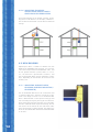
The Hybalansplus ventilation system provides the
supply as well as the discharge of ventilating air with
the highest possible energy saving and maximum
convenience. A Heat Recovery Ventilation (HRV) unit
to be selected as desired, provides the movement
of ventilating air. The other system parts of the
Hybalansplus take care of an optimal movement of
air, to and from the various rooms to be ventilated.
Two air distribution boxes are connected to the HRV
unit, they ensure an optimal balance between inlet
and return air. These distribution boxes are also
fitted with acoustic dampers. The flexible synthetic
ducts, red for the return air and blue for fresh air,
distribute the air to and from the various rooms.
Fresh air is distributed to the living room and
bedrooms via the supply valves. The same quantity
of (polluted) air is extracted via the valves from the
kitchen, bathroom and toilet(s). The required spaces
underneath the inner doors contribute to a good movement of air in the house. The system is completely
self-supporting and operates independently.
1.2 APPLICATIONS
Type of buildings
Hybalansplus can be applied to all kinds of buildings,
small utility buildings, with renovation projects as
well as newly constructed buildings.
2
1.3 SYSTEMATIC CONSTRUCTION
3
1.4 ADVANTAGES OF THE
HYBALANSPLUS SYSTEM
1 Minimal maintenance
Ê
4 Simple adjustment of the system
The air quantities per air valve are simply centrally
adjusted in the air distribution boxes. Adjustment
of the air valves is unnecessary.
UÊ Ê >Ê>Ìi>ViÊLiV>ÕÃiÊvÊÌ
iÊ>««V>tion of one diameter without branches per
suction and supply valve. Gradual crossings
5 Non-adjustable air valves
The air valves are non-adjustable. Also during
between the various parts of the system take
clean ing there no risk whatsoever that the air
care of the permanent absence of turbulences and prevent unnecessary loss of pressu-
distribution is altered, because there are no possibilities for adjustment present. This guarantees
re and dirt deposit. The antistatic qualities of
the synthetic material contribute to a slower
correctly adjusted values at all times.
dirt deposit.
Ê
UÊ /
Ê
iÊ ViÛiÀÊ `iÃ}Ê vÊ Ì
iÊ Û>ÛiÃ]Ê Ê «>ÀÌVÕ>ÀÊ
the wide dimensions of the opening, minimizes
Ê
UÊ Ê >Ìi>ViÊÃÊÌi`ÊÌÊVi>}ÊvÊÌ
iÊVponents.
6 Cooling option possible
Depending on the type of waste heat recovery
unit, the use of night cooling is possible.
the chance for dirt deposit.
2 Noiseless
Ê
Hybalansplus has a limited number of system
components, which offers advantages in stock
management, transport and construction.
UÊ Ê `ÕÃÌiÌÊvÊ>ÀʵÕ>ÌÌiÃ]ÊÜ
V
ÊÃÊÀiësible for the development of disturbing noise,
does not take place in living rooms.
8 Simple construction
Construction is carried out with one-diameter
Ê
UÊ Ê ÀÊ `ÃÌÀLÕÌÊ LÝiÃÊ >ÀiÊ vÌÌi`Ê ÜÌ
Ê ÌiÀ>Ê
flexible synthetic duct. This can be easily shor-
Ê
acoustic damping.
UÊ ÊVÀÃÃÊÌ>ttt
tened to the required length. The click connection
between the flexible synthetic ventilating ducts,
Ê
UÊ Ê ÕiÊ ÌÊ ÜÊ ÀiÃÃÌ>ViÊ ÃÃiÃ]Ê Ì
iÊ ÜÀ}Ê
air valves and the air distribution box makes
point and fan motor rpm of the HRV unit are
reduced. This creates an extra reduction of
screwing with self-tappers, taping & gluing the
connections unnecessary. This means that the
the system noise.
system is designed for reliability. The environmental impact of this construction is significant.
3 No draughts
Due to the use of special air valves, air is blown
into the living areas with low air speed, which
prevents draughts.
4
7 Limited number of system components
By removing toxic glues & duct tape from the
installation there is less waste & less packaging.
2 REQUIREMENTS
2.1 AIR QUANTITY REQUIREMENTS
ACCORDING TO BUILDING
REGULATIONS
The required air quantities to be supplied and discharged to and from the various rooms should be
calculated in accordance with the national building
regulations. Various additional conditions, as mentioned in the construction documents, should be
taken into account (e.g. quality guarantee conditions)
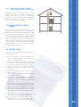
2.2 FIRE
Care should be taken to observe the building design
parameters in relation to fire containment. Passive fire
prevention solutions are available for most scenarios.
2.3 CROSS TALK
The rooms that are to be ventilated with Hybalansplus
flexible synthetic ventilating ducts are not mutually
connected with, for example, T-pieces. Due to the
fact that every room has its own flexible synthetic
duct sound transmission via the ducts of the mutual
rooms is prevented.
2.4 DISTANCE BETWEEN OUTLET
ON THE ROOF AND INLET ON
THE ROOF OR IN THE WALL
The selected positions for the outlet and the inlet
should be in compliance with national regulation to
prevent recirculation of the used air in the inlet of
the system.
5
6
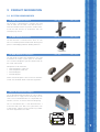
3 PRODUCT INFORMATION
3.1 SYSTEM COMPONENTS
HR WTW 3000 roof terminal
£xäÊ£näÊ
£näÊÊÓ£ä
£xäÊ£näÊ
£näÊÊÓ£ä
£xäÊ£näÊ
£näÊÊÓ£ä
The terminal is mounted with a synthetic tile, lead
slate or collar for flat roofs. The roof terminal is
fitted with EPS-insulation to prevent condensation.
Install the roof terminal in accordance with the
accompanying manual.
HR WTW 3000 wall terminal
The wall terminal is used to draw in fresh air. The
inlet is insulated to prevent condensation forming & to
prevent “cold bridging” between building elements.
HR WTW 3000 duct components
The high-grade synthetic duct components are used
to connect the various system parts on the WTWunit. The duct components prevent condensation on
the inside and outside.
Components to be mounted:
UÊ `ÕVÌÊV«iÌÃÊ£äääÊ
UÊ `ÕVÌÊV«iÌÃÊxääÊ
UÊ Li`Ê{xÊ`i}ÀiiÃ
UÊ Li`ÊäÊ`i}ÀiiÃ
Various connection pieces. Please install in accordanViÊÜÌ
ÊÌ
iÊ,Ê7/7ÊÎäääÊÃÌ>>ÌÊÀi}Õ>ÌðÊ
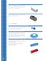
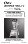
HB-plus distributionbox complete
The air distribution box distributes air. The air distribution box for air supply and air discharge are the
same. The air distribution box has 12 possible connections, and has an internal acoustic dampening.
The air distribution box is also delivered with a
re striction table (see: 9.2). The system data such
as duct length, capacity and restriction ring number
are to be registered in this table.
85
271
501
233
569
207
105
603
MATERIAL
-
TOOL.NR.
7
HB-plus air distribution box base
When the air distribution box is partly set in concrete, an air distribution box base can be used. This
base is fitted with a flat lid to prevent damage and
pollution of the air distribution box.
HB-plus air distribution box upper part
The air distribution box upper part is made out of EPP
foam with closed cell structure.
3.1.1. ACCESSORIES
HB-plus connecting piece air distribution box complete
The connecting piece connects the ventilating duct
to the air distribution box (screw connection). It is
also the location of the restriction ring.
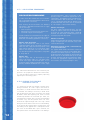
HB-plus restriction ring air distribution box
The restriction ring is mounted in the connecting
piece of the air distribution box. The air inlet is adjusted by cutting out one or more rings. In this way,
each duct has its own fixed adjustment. The inlet
can be determined with the help of the calculation
programme on www.muelink-grol.nl
HB-plus flex-synthetic duct for supply air (blue)
The flexible synthetic ventilating duct has a minimal
Li`}ÊÀ>`ÕÃÊvÊ£xäÊ°Ê/
iÊ`ÕVÌÃÊ>ÀiÊ`iÛiÀi`Ê
Ê>ÊÀÊvÊxäÊiÌÀiðÊ
Material outside: HDPE (high density polyethylene)
Material inside: LDPE (low density polyethylene)
Outer diameter: 92,3 mm
Inner diameter: 75 mm
8
blue
red
HB-plus connecting piece
Connecting piece to connect two flexible synthetic
ventilating ducts.
HB-plus air valve connecting piece 90° including
mounting plate, seal ring and dust cap
The ventilating connection piece is used to connect
an air valve at a right angle onto the flexible syntheÌVÊ`ÕVÌ°ÊÌÊÃÊVÌÕÕÃÞÊÛ>À>LiÊÕ«ÊÌÊ£ääÊÊLÞÊ
means of a mounting plate. The air valve connecting
piece is secured to the surface with the mounting
plate. The cross-shaped serrated edge facilitates
attachment to reinforcements with steel wire.
HB-plus ventilation connection, straight, including mounting plate
Ventilation connection piece for straight installation.
ÌÊÃÊVÌÕÃÞÊÛ>À>LiÊÕ«ÊÌÊ£ääÊÊLÞÊi>ÃÊvÊ
a mounting plate.
HB-plus dust cap flexible synthetic duc
The outer ends of the flexible synthetic duct that have
not been connected to one of the Hybalansplus components should be temporarily fitted with a dust cap,
as to prevent fouling during the building process. This
part can also be used to code ventilation ducts.
HB-plus bend conductor
ÀÊ Ì
iÊ ÕÌ}Ê vÊ >Ê ä`i}ÀiiÃÊ Li`Ê vÀÊ Ì
iÊ
floor / ceiling, a galvanised metal bend conductor is
used. It is fitted with a quick-acting closure.
9
HB-plus clamping bracket 90°
For the mounting of the flexible synthetic ducts to
the floor / wall a galvanised metal clamping bracket
is used.
HB-plus extension piece ceiling cover ring
Ê V>ÃiÊ vÊ >Ê vÀÊ Ì
ViÃÃÊ vÊ ÀiÊ Ì
>Ê £ääÊ Ê
one or more extension pieces will be used. For every
extension piece ceiling cover ring the ceiling ring is
iÝÌi`i`ÊÜÌ
Ê{äÊ°
3.12
AIR VALVES
The Hybalansplus system gives a choice of various
air valves. All air valves are suitable for supplying
and extaction of air. The air valve type Kwadrant can
only be mounted in a wall in case of supplying air.
Type air valves
10
Max. discharge
in l/s
Feature
Kwadrant
21
an air valve with almost level ejection
and low resistance
Turn
21
an alignable, inducing air valve
Model
Max. supply
in l/s
Conus
14
21
a fixed inducing air
valve
Disc
14
21
a fixed inducing air
valve
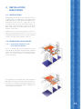
4 INSTALLATION
DIRECTIONS
4.1 INSTRUCTIONS
Depending on the design of the installation and the
available room, the application of the Hybalansplus
makes demands on, for example, the dwelling. The
dimensions of the recesses, cable ducts or the
installation room will have to be determined at an
early stage. The accessibility as well as the possibility to dissemble the air distribution box for maintenance are essential.
Hybalansplus is a house ventilating system for renovation and new constructions. In this case, the
renovation and the IFD-variant are surface mounted.
In other situations the installation is built in.
4.2 RENOVATION APPLICATION
4.2.1 MOUNTING EXAMPLES AIR
DISTRIBUTION BOXES
This is an example of a variant where the air distribution boxes have been mounted above a lowered
ceiling. The lowered ceilings will have to be constructed in such a way that the air distribution boxes
remain accessible.
An example of an installation where the air distribution boxes have been mounted in the same room as
the HRVunit. A lowered ceiling keeps the ducts out
of sight. The air distribution boxes should remain
accessible for maintenance.
11
4.2.2 MOUNTING EXAMPLES
INSTALLATION SINGLE-FAMILY
DWELLINGS FOR RENOVATION
Vertical distribution of the flexible synthetic ventilating ducts can be done via, for example, cable ducts.
The horizontal distribution can be done via lowered
ceilings.
4.3 NEW BUILDING
Hybalansplus offers a number of solutions for new
buildings for embedding into concrete. Just to name
a few: for example concrete hollow-bore slabs, and
on-site poured concrete (tunnel) floors. In all cases, the concrete is poured over the ducts, and
the air distribution boxes can be mounted in various
ways, depending on the location of the waste heat
recovery unit.
4.3.1 MOUNTING VARIANTS NEW
BUILDING (SURFACE MOUNTING /
BUILDING IN)
The air distribution box consists of a metal base and
a synthetic upper part. The base can be put in concrete in the rough structure. An air distribution box
base is delivered with a lid to prevent filling up and
internal fouling during the pouring of the concrete.
Prior to the pouring of the concrete, the air distribution box should be fixed to prevent floating. Ensure
free access to the closure on the short outer sides
after the concrete has been poured. The upper part
of the air distribution box should remain demountable
at all times.
12
4.3.2 MOUNTING VARIANTS NEWLY
BUILT SINGLE-FAMILY DWELLINGS
Vertical distribution of the flexible synthetic ventilating ducts is done via, for example, cable ducts or
empty corners beside a staircase. The horizontal
distribution is done via the floors. The air distribution
boxes are located in the same room as the HRV unit.
Other variants also remain possible.
4.4 APPLICATION OF COOKER
HOODS
Connecting a cooker hood (without fan motor) is only
possible when the Hybalansplus ventilating system is
permanently powered on. These cooker hoods should
be connected with two Hybalansplus flexible synthetic
ducts. The operation of the cooker hoods should be
such that the hood is able to catch sufficient steam at
125 m3/h. Cooker hoods with an engine cannot be
connected to the Hybalansplus system. These cooker
hoods should be fitted with their own discharge duct
directly outwards. This has no influence on the operation of the Hybalansplus system.
4.5 DESIGN STEPS
In order to design a good installation, the following
steps should be taken:
1
Use the ventilating calculation according to the
2
national building regulations as basis for the design of the Hybalansplus system
Based on the ventilating calculation, determine the
number of air valves per room to be ventilated. See
3.1.2 for the maximum capacity per air valve.
3
4
5
Determine the make and type of the HRV unit,
taking into account the air capacity and conveying height.
Determine the set-up location of the waste heat
recovery unit.
Determine the arrangement of the Hybalansplus
air distribution boxes.
6Ê Ê iÌiÀiÊ Ì
iÊ 7/7Ê ÎäääÊ `ÕVÌÊ >ÀÀ>}iiÌÊ
between air distribution boxes, waste heat recovery unit, fresh air suction and discharge
provisions.
7
Determine the course of the blue flexible synthetic
ducts and the length between the air distribution
box and the air valves with regard to the air supply.
8
Determine the course of the red flexible synthetic
ducts and the length between the air distribution box and the air valves with regard to the air
9
discharge.
Calculate the installation with regard to resistance
with the help of the calculation programme.
10 Check the design for accessibility of the air
distribution boxes in order to be able to fit the
restriction rings and carry out maintenance work.
13
4.5.1 CALCULATION PROGRAMME
CALCULATION PROGRAMME
In order to be able to determine the air distribution, a calculation with the Muelink & Grol calculation programme is necessary.
After entering of the calculation, the following
information is obtained on behalf of the air supply
and air discharge:
UÊ ÌÌ>Ê>ÀʵÕ>ÌÌÞ
UÊ «iÀ>Ì}Ê«ÀiÃÃÕÀiÊÜ>ÃÌiÊ
i>ÌÊÀiVÛiÀÞÊÕÌ
UÊ ÀiÃÌÀVÌÊÀ}Ê«iÀÊÛiÌ>Ì}Ê`ÕVÌ°
In order to obtain this information for the supply air
distribution box as well as the discharge air distribution box, the following procedure is necessary:
Column: room description
Copy the description per room in the column
“room description” of the calculation. If there are
more than one supply and discharge point in one
room, please indicate so. In case of three supply
points in the living room, this can be entered in
the room description as: living room 1, living room
2, living room 3.
Column: flow
Copy the supply and / or discharge air l/s per
room in the column “flow” (l/s). The flow is entered for each supply and discharge point. In case
of several supply and discharge points the total air
quantity should be divided over the various supply
The information obtained from the calculation programme is very important. Without this information,
it is not possible to generate a properly operating
Hybalansplus ventilating system.
4.5.2 CODING THE FLEXIBLE
SYNTHETIC DUCTS
It is important to code the flexible synthetic ducts
during installation. At a later stage in the construction process, it will be clear for which room the duct
is intended. This coding is necessary in order to be
able to determine later which restriction ring should
be fitted in which duct (opening). So, there is a fixed
relationship between the ventilation per room, the
connected flex-synthetic duct and the corresponding
restriction ring. The flex-synthetic ducts are shortened to the required length and a dust cap is fitted
during the construction of the carcass of the building.
In this way the flex-synthetic ducts are kept clean, and
the coding can be applied with a waterproof marker
pen. If the air distribution box is put in concrete, the
flex-synthetic ducts are connected to it. The coding is
14
and discharge points. If for a living room, a total
quantity of 42 l/s should be supplied over three
supply points, the following values should be entered in the column “flow” of the table: 14, 14 and
14 l/s. The division of the total air quantity is determined based on the values that are mentioned
on, for example, a construction drawing.
Column: duct length
For every supply and discharge point, the duct
length (in metres) from the air distribution box
up to the air valve connecting piece, should be
entered. The duct length should comply with the
accompanying room description.
Column: restriction
After entering the room description, flow and duct
length, the opening of the restriction ring is automatically determined.
Connection material of wall / roof terminal up
to air distribution box
/
iÊ >««i`Ê 7/7Ê ÎäääÊ ViVÌÊ >ÌiÀ>Ê vÊ
wall / roof terminal up to the air distribution box is
entered in the column “quantity”. The quantity entered constitutes for example the total number of
bends from the air distribution box up to the roof
terminal. The data entered are important in order
to select the appropriate capacity of the waste
heat recovery unit (conveying height in $Pa).
indicated on the sticker that will be attached to the
4.6.4 NON-ADJUSTABLE FAN MOTORS
air distribution box. It will be clear in the completion
phase to which connection on the air distribution box
the restriction ring should be fitted.
This type of motor operates at one and the same
speed, despite increase or decrease of unexpected
resistances in the system. The engines cannot be ad-
A restriction table which is part of the installation is
justed to the correct working point, either manually or
via software. Hence, this type of waste heat recovery
included in the user manual for the resident of the
house (see: paragraph 9.2). This table should be
unit cannot be used for the Hybalansplus system.
completed for maintenance and inspection purposes.
4.7 INSTALLATION OF COMPONENTS
4.6 ADJUSTMENT OF HRV UNITS
4.7.1 SHORTENING THE FLEXIBLE
SYNTHETIC DUCT
Apart from other possible intelligent adjustments,
the waste heat recovery units have four main types
with regard to the applied motors. It is important
to know which type of fan motor is fitted to ensure
proper operation of the Hybalansplus system.
The four main types are:
UÊ VÃÌ>ÌÊÛÕiÊi}iÃ
UÊ «ÀiÃÃÕÀiVÌÀi`Êi}iÃ
UÊ >`ÕÃÌ>LiÊi}iÃ
UÊ >`ÕÃÌ>LiÊi}iÃ
The flexible synthetic duct can be easily shortened:
1
Roll the flexible synthetic out on the floor / ceiling
2
/ wall to be installed.
Mount one side of the flexible duct on the
4.6.1 CONSTANT VOLUME FAN MOTORS
Hybalansplus component to be installed with the
The HRV unit is set to always move the total adjusted air quantity. The manner of adjustment differs
per manufacturer. For a correct adjustment, the
3
with appropriate tools (for example a knife). Pre-
calculated total air quantity as calculated with the
Muelink & Grol calculation programme is needed.
4
4.6.2 PRESSURE-CONTROLLED FAN
MOTORS
click-connection.
Shorten the other side to the required length
vent burrs on the inside of the duct.
After the duct has been shortened, a seal ring
should be placed on the first intact groove of
the duct. This will prevent air leakages between
connection pieces and the flexible synthetic duct.
The fans keep the pressure in the ventilating system
constant. The way in which the fans are adjusted
differs per manufacturer. Please refer to the manual
of the manufacturer concerned. For a correct
adjustment, the calculated total system resistance
as calculated with the Muelink & Grol calculation
pro gramme is needed.
4.6.3 ADJUSTABLE SPEED FAN MOTORS
This type of motor operates at one and the same
speed, despite increase or decrease of the resistances and air quantities. The fans have to be
adjusted manually or via software to the correct
working point. The manner of adjustment differs
per manufacturer. Please refer to the manual of
the manufacturer concerned. For a correct adjustment, the calculated total air quantity and calculated
total resistance as calculated with the Muelink &
Grol calculation programme are needed in order to
determine the correct working point.
15
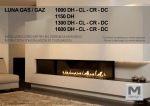
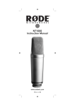
4.7.2 MOUNTING THE FLEXIBLE
SYNTHETIC DUCT ON THE AIR
DISTRIBUTION BOX
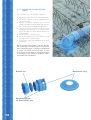
1
Remove the upper part of the air distribution box
by loosening both click-closures.
2
3
Remove the correct number of blue covers with
a flat screwdriver.
Carefully press the acoustic damping rings from
4
the openings in the air distribution box.
Place the connection piece on the outside of
these openings and secure them with the sup-
5
plied synthetic nut on the air distribution box.
Mount the shortened flexible synthetic duct with
6
a seal ring on the connection piece and close the
two clamps.
After the flexible synthetic duct has been mounted,
close the upper part of the air distribution box to
prevent pollution during the building process.
Air distribution box
upper part
Connecting piece
air distribution box
Seal ring
Air distribution box
base
Flexible synthetic duct
16
Restrictiering air distribution box
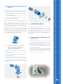
4.7.3 MOUNTING THE HYBALANSPLUS
FLEXIBLE DUCTS
In order to prevent the ducts from floating, they can
be attached to the floor construction with clamping
brackets. When planning the cable ducts on the
floor, an intact reinforcement should be taken into
account. Possible partial removal of the reinforcement can only be done after consultation with the
supplier of the floors. In case of concrete hollow fibre
slabs, with or without cable recesses, the ducts are
secured with, for example, the specially designed variable clamping brackets and bend conductors.
The bend conductor ensures that a tight bend can be
realised swiftly and effectively. It operates as follows:
1
2
Mount the bend conductor on the floor or wall.
Press the Hybalansplus flexible duct component
Ê Ì
iÊ Li`Ê V`ÕVÌÀÊ Ê ÃÕV
Ê >Ê Ü>ÞÊ Ì
>ÌÊ >Ê ä
3
degrees bend is created.
Close the clamp over the flexible synthetic duct
component.
4.7.4 INTERSECTING DUCTS AND
CABLES
Intersecting the flexible synthetic ducts in concrete
floors is not possible because of the thickness of the
finishing layer. Intersecting with for example electricity, water and gas pipes, is with regard to the
limited height, no problem. In a surface mounting
situation the possibilities for intersection depend on
the distance between the constructive ceiling and
the lowered ceiling.
17
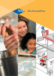
4.7.5 MOUNTING THE RESTRICTION
RINGS
The restriction rings are mounted as follows:
1
Remove the upper part of the air distribution box.
2
Loosen the synthetic nut of the required connection on the inside.
Remove the correct number of rings until the
3
number of the opening corresponds with the number according to the calculation programme.
4
Take the restriction ring to the inside of the air
distribution box and place it on the connection
concerned with the cone pointed towards the
5
ventilating duct.
Reattach the nut removed earlier.
6
Record the opening of the restriction ring and
7
the room in the restriction table.
If necessary, repeat the procedure for an other
connection.
The restriction rings provide a correct distribution of the supply and discharge air in the house.
Every ventilating duct – restriction combination
is unique and cannot be interchanged. In case
of alteration of the house or change of function
all restriction rings should be adapted in accor dance with new calculations.
Plastic nut
Connecting piece
air distribution box
18
Restriction ring
4.8 MOUNTING ADAPTERS AND AIR
VALVES
In case of a surface-mounted installation, the following options apply for the mounting of the air valves:
UÊ Ê ÀÊ Û>ÛiÃÊ ÕÌi`Ê Ê iÊ ÜÌ
Ê Ì
iÊ ÛiÌ>Ì}Ê
duct. For example for mounting in walls or reveals of lowered ceilings.
UÊ Ê ÀÊÛ>ÛiÃÊÕÌi`ÊÕ`iÀÊ>Êä`i}ÀiiÃÊ>}iÊvÀÊ
mounting in lowered ceilings.
When used in a poured concrete floor of various
flooring systems, an air valve connection piece of
äcÊÃÊÕÃi`ÊvÀÊÌ
iÊÕÌ}ÊvÊÌ
iÊ>ÀÊÛ>Ûi°Ê/
ÃÊ
will bridge the distance between the ventilating duct
5 MAINTENANCE
in the concrete and the ceiling. The air valve connecÌÊ«iViÊ
>ÃÊ>Ê>ÝÕÊÃâiÊvÊ£ääÊÊ>`ÊÃÊ>`
justed with a swivel. The mounting plate is attached
The low air speed combined with the smooth inside
of the Hybalansplus flexible synthetic ducts, and the
to the concrete. The air valve connection piece can
resulting laminar air flow contribute to a very low
be lengthened to the desired length with extension
pieces. The cam on top of the adapter is used to at-
dirt deposit. The deposit of dirt is even more reduced by keeping the suction valves clean. In this
tach the connection piece with iron wire.
way, turbulent air flows and resulting pollution are
prevented.
5.1 MAINTENANCE WORK FOR THE
INSTALLER
UÊ Ê À>ÜÊÌ
iÊÀiÃ`i̽ÃÊ>ÌÌiÌÊÌÊÌ
iÊv>VÌÊÌ
>ÌÊÌ
iÊ
air valves should be cleaned in accordance with
the Hybalansplus user instructions.
UÊ ÊëiVÌÊ Ì
iÊ ÀiÃÌÀVÌÊ À}Ã]Ê Ã`iÊ >ÀÊ `ÃÌÀLÕ
4.8.1 MOUNTING AIR VALVES IN AIR
VALVE CONNECTION PIECE - 0°
AND 90° CONNECTION
1
tion boxes and the inside of the flexible synthetic
duct for dirt or pollution.
UÊ Ê
i>}ÊvÊÌ
iÊÀiÃÌÀVÌÊÀ}ÃÊVÃÃÌÃÊvÊ«i
Shorten the flexible synthetic ducts to the required
ning of the air distribution box and cleaning the
inside. Remove and clean the restriction rings.
length and attach a seal ring in accordance with
Reassemble in reverse order.
2
paragraph 5.1.1.
Click the air valve connection piece onto the flexi-
3
ble synthetic duct.
Adjust the height with the help of the mounting
plate. The bottom of the air valve connection pie-
4
ce should not protrude from the wall / ceiling.
Click as many extension pieces on the ceiling ring
as needed.
19
Please note: Each restriction ring has a fixed lo-
Adjusting the air quantities by removing the restric-
cation. Changing the restriction rings will prevent
a correct operation of the system. The correct
tion rings, contrary to what had been indicated in
the calculation, will imbalance the installation and
restrictions are registered in the restriction table
will render an effective operation of the installation
in the user manual (see paragraph 9.2) and on the
sticker attached to the plenum. The air valves and
impossible and the warranty will expire.
restriction rings can be cleaned in a dishwasher.
UÊ ÊÊÌ
iÊÃiVÌÊvÊÌ
iÊ>ÀÊÃÕVÌÊÌ
iÊiÛiÊvÊ«
7 ENVIRONMENT
lution is mainly determined by the maintenance
to the discharge valves and suck-in openings.
Muelink & Grol pays considerable attention to an
Dirt is minimal in the especially designed flowing
environmental-friendly production. All used materi-
duct without blind angles, as is the case with
the Hybalansplus. When dirt is found at an in-
als are suitable for recycling. The type of synthetic
material used is indicated on the products, where
spection it is recommended to clean all flexible
synthetic ducts.
necessary. The parts do no contain detrimental substances, such as halogens (fire-retardant).
UÊ Ê ÀÊ>Ìi>ViÊÌÊÌ
iÊ,6ÊÕÌ]Ê«i>ÃiÊÀiviÀÊÌÊ
Ì
iÊ>Õv>VÌÕÀiÀ½ÃÊ>Õ>°
Good and regular maintenance will result in a system
8 AVAILABILITY
that operates properly for a longer period of time,
which will benefit the quality of the inner atmosphere.
Muelink & Grol B.V.
*ÃÌLÕÃÊxä
6 WARRANTY
ÇääÊÊÀ}iÊ>`®
/i°\ÊÊ Ê
ÕiÊEÊÀÊ}ÛiÃÊ>Ê£äÞi>ÀÊ}Õ>À>ÌiiÊÕ«ÊV
³Î£Êä®xäÊΣÎÊÊ{{
/iiv>Ý\ÊÊ ³Î£Êä®xäÊΣnÊx{ÊÓÎ
pletion. The following conditions apply if:
UÊ Ê" ÞÊÞL>>ëÕÃÊÃÞÃÌiÊV«iÌÃÊ
>ÛiÊLiiÊ
used.
UÊ ÊÃÌ>>ÌÊ Ü>ÃÊ V>ÀÀi`Ê ÕÌÊ Ê >VVÀ`>ViÊ ÜÌ
Ê
the Hybalansplus installation instructions.
UÊ /
Ê
iÊ ÞL>>ëÕÃÊ V>VÕ>ÌÊ «À}À>iÊ
>ÃÊ
been used.
UÊ /
Ê
iÊ`>Ì>ÊiÌiÀi`ÊÊÌ
iÊÀiÃÌÀVÌÊÌ>LiÊVÀÀiÃ
pond with the installation concerned.
UÊ Ê/
iÊ>ÀʵÕ>ÌÌiÃ]ÊÌ
>ÌÊ
>ÛiÊLiiÊ`iÌiÀi`ÊvÀÊ
the building application, can be produced.
UÊ /
Ê
iÊÜ>ÃÌiÊ
i>ÌÊÀiVÛiÀÞÊÕÌÊ«iÀ>ÌiÃÊVÀÀiVÌÞÊ
and has been adjusted in accordance with the
values from the calculation programme.
UÊ Ê/
iÊ >ÀÊ Û>ÛiÃ]Ê iÀÊ `ÕVÌÊ V«iÌÃÊ >`Ê >ÀÊ
distribution boxes have been installed in accordance with this technical manual.
20
E-Mail:
[email protected]
Internet:
www.muelink-grol.nl
21
9 APPENDIX TECHNICAL INFORMATION
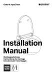
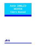
9.1 ACOUSTIC DAMPING AIR DISTRIBUTION BOX
Demping
damping
airluchtverdeelkast
distribution box
30
25
[dB]
20
15
10
5
0
63
125
250
500
1000
2000
4000
8000
[Hz]
9.2 RESTRICTION TABLE
restriction table
Air supply
1
2
3
4
5
11
12
6
Connection
Ê
£Ê
Ê
ÓÊ
Ê
ÎÊ
Ê
{Ê
Ê
xÊ
Ê
ÈÊ
Ê
ÇÊ
Ê
nÊ
Ê
Ê
Ê £äÊ
Ê ££Ê
Ê £ÓÊ
7
8
9
10
Room
°°°°°°°°°°°°°°°°°°°°°°Ê
°°°°°°°°°°°°°°°°°°°°°°Ê
°°°°°°°°°°°°°°°°°°°°°°Ê
°°°°°°°°°°°°°°°°°°°°°°Ê
°°°°°°°°°°°°°°°°°°°°°°Ê
°°°°°°°°°°°°°°°°°°°°°°Ê
°°°°°°°°°°°°°°°°°°°°°°Ê
°°°°°°°°°°°°°°°°°°°°°°Ê
°°°°°°°°°°°°°°°°°°°°°°Ê
°°°°°°°°°°°°°°°°°°°°°°Ê
°°°°°°°°°°°°°°°°°°°°°°Ê
°°°°°°°°°°°°°°°°°°°°°°Ê
Capacity in l/s
°°°°°°°°°°°°°°°°°°°Ê
°°°°°°°°°°°°°°°°°°°Ê
°°°°°°°°°°°°°°°°°°°Ê
°°°°°°°°°°°°°°°°°°°Ê
°°°°°°°°°°°°°°°°°°°Ê
°°°°°°°°°°°°°°°°°°°Ê
°°°°°°°°°°°°°°°°°°°Ê
°°°°°°°°°°°°°°°°°°°Ê
°°°°°°°°°°°°°°°°°°°Ê
°°°°°°°°°°°°°°°°°°°Ê
°°°°°°°°°°°°°°°°°°°Ê
°°°°°°°°°°°°°°°°°°°Ê
restriction table
Air discharge
1
2
3
4
5
11
12
6
Connection
Ê
£Ê
Ê
ÓÊ
Ê
ÎÊ
Ê
{Ê
Ê
xÊ
Ê
ÈÊ
Ê
ÇÊ
Ê
nÊ
Ê
Ê
Ê £äÊ
Ê ££Ê
Ê £ÓÊ
22
Restriction
iÊÉÊÈÎÊÉÊxxÊÉÊ{nÊÉÊ{ÓÊÉÊÎÈÊÉÊÎä
iÊÉÊÈÎÊÉÊxxÊÉÊ{nÊÉÊ{ÓÊÉÊÎÈÊÉÊÎä
iÊÉÊÈÎÊÉÊxxÊÉÊ{nÊÉÊ{ÓÊÉÊÎÈÊÉÊÎä
iÊÉÊÈÎÊÉÊxxÊÉÊ{nÊÉÊ{ÓÊÉÊÎÈÊÉÊÎä
iÊÉÊÈÎÊÉÊxxÊÉÊ{nÊÉÊ{ÓÊÉÊÎÈÊÉÊÎä
iÊÉÊÈÎÊÉÊxxÊÉÊ{nÊÉÊ{ÓÊÉÊÎÈÊÉÊÎä
iÊÉÊÈÎÊÉÊxxÊÉÊ{nÊÉÊ{ÓÊÉÊÎÈÊÉÊÎä
iÊÉÊÈÎÊÉÊxxÊÉÊ{nÊÉÊ{ÓÊÉÊÎÈÊÉÊÎä
iÊÉÊÈÎÊÉÊxxÊÉÊ{nÊÉÊ{ÓÊÉÊÎÈÊÉÊÎä
iÊÉÊÈÎÊÉÊxxÊÉÊ{nÊÉÊ{ÓÊÉÊÎÈÊÉÊÎä
iÊÉÊÈÎÊÉÊxxÊÉÊ{nÊÉÊ{ÓÊÉÊÎÈÊÉÊÎä
iÊÉÊÈÎÊÉÊxxÊÉÊ{nÊÉÊ{ÓÊÉÊÎÈÊÉÊÎä
7
8
9
10
Room
°°°°°°°°°°°°°°°°°°°°°°Ê
°°°°°°°°°°°°°°°°°°°°°°Ê
°°°°°°°°°°°°°°°°°°°°°°Ê
°°°°°°°°°°°°°°°°°°°°°°Ê
°°°°°°°°°°°°°°°°°°°°°°Ê
°°°°°°°°°°°°°°°°°°°°°°Ê
°°°°°°°°°°°°°°°°°°°°°°Ê
°°°°°°°°°°°°°°°°°°°°°°Ê
°°°°°°°°°°°°°°°°°°°°°°Ê
°°°°°°°°°°°°°°°°°°°°°°Ê
°°°°°°°°°°°°°°°°°°°°°°Ê
°°°°°°°°°°°°°°°°°°°°°°Ê
Capacity in l/s
°°°°°°°°°°°°°°°°°°°Ê
°°°°°°°°°°°°°°°°°°°Ê
°°°°°°°°°°°°°°°°°°°Ê
°°°°°°°°°°°°°°°°°°°Ê
°°°°°°°°°°°°°°°°°°°Ê
°°°°°°°°°°°°°°°°°°°Ê
°°°°°°°°°°°°°°°°°°°Ê
°°°°°°°°°°°°°°°°°°°Ê
°°°°°°°°°°°°°°°°°°°Ê
°°°°°°°°°°°°°°°°°°°Ê
°°°°°°°°°°°°°°°°°°°Ê
°°°°°°°°°°°°°°°°°°°Ê
Restriction
iÊÉÊÈÎÊÉÊxxÊÉÊ{nÊÉÊ{ÓÊÉÊÎÈÊÉÊÎä
iÊÉÊÈÎÊÉÊxxÊÉÊ{nÊÉÊ{ÓÊÉÊÎÈÊÉÊÎä
iÊÉÊÈÎÊÉÊxxÊÉÊ{nÊÉÊ{ÓÊÉÊÎÈÊÉÊÎä
iÊÉÊÈÎÊÉÊxxÊÉÊ{nÊÉÊ{ÓÊÉÊÎÈÊÉÊÎä
iÊÉÊÈÎÊÉÊxxÊÉÊ{nÊÉÊ{ÓÊÉÊÎÈÊÉÊÎä
iÊÉÊÈÎÊÉÊxxÊÉÊ{nÊÉÊ{ÓÊÉÊÎÈÊÉÊÎä
iÊÉÊÈÎÊÉÊxxÊÉÊ{nÊÉÊ{ÓÊÉÊÎÈÊÉÊÎä
iÊÉÊÈÎÊÉÊxxÊÉÊ{nÊÉÊ{ÓÊÉÊÎÈÊÉÊÎä
iÊÉÊÈÎÊÉÊxxÊÉÊ{nÊÉÊ{ÓÊÉÊÎÈÊÉÊÎä
iÊÉÊÈÎÊÉÊxxÊÉÊ{nÊÉÊ{ÓÊÉÊÎÈÊÉÊÎä
iÊÉÊÈÎÊÉÊxxÊÉÊ{nÊÉÊ{ÓÊÉÊÎÈÊÉÊÎä
iÊÉÊÈÎÊÉÊxxÊÉÊ{nÊÉÊ{ÓÊÉÊÎÈÊÉÊÎä
9.3 MAINTENANCE INSTRUCTIONS
FOR USERS
Dear user,
Your home has been fitted with a Hybalansplus ventilating system that provides supply and discharge of
ventilating air in your home with the highest possible
energy saving and maximum comfort. This is done
with a ventilating unit (waste heat recovery unit)
which provides discharge of the polluted air from
your kitchen, bathroom or toilet. The air that is discharged from your home is used to preheat the supplied air. This is done in such a way that the air is
mixed with the supplied fresh air from outside. The
waste heat recovery unit is fitted with a so-called
i>ÌÊ iÝV
>}iÀ°Ê /
ÃÊ ÃÊ ÞÕÀÊ }Õ>À>ÌiiÊ vÀÊ £ääÊ ¯Ê
fresh outside air.
The air in your home is supplied and discharged by
two unique air distribution boxes placed near the
ventilating unit. Several air valves and supply air valves have been fitted in the living quarters of your
home. That is your guarantee for a comfortable and
energy-saving ventilating system.
Hybalansplus has the following air valves:
23
Cleaning the air valves:
UÊ Ê* ÕÊ Ì
iÊ iÀÊ ViÊ vÀÊ Ì
iÊ ÃÞÌ
iÌVÊ À}Ê LÞÊ
giving a slight tug. The white outer ring may also
come loose from the ceiling or wall, but that is
no problem.
UÊ Ê
i>Ê Ì
iÊ Ã`iÊ vÊ Ì
iÊ Ü
ÌiÊ ÕÌiÀÊ À}Ê ÜÌ
Ê >Ê
damp cloth or vacuum cleaner.
UÊ Ê
i>ÊÌ
iÊiÀÊViÊÊÌ
iÊÃ>iÊÜ>Þ°ÊÌ
Ê«>ÀÌÃÊ
can also be cleaned in a dishwasher.
UÊ Ê, i>ÃÃiLiÊ Ì
iÊ >ÀÊ Û>ÛiÊ LÞÊ «ÀiÃÃ}Ê Ì
iÊ iÀÊ
cone in the outer ring.
With this type of air valve, the synthetic inner ring is
not visible. When the valve is removed, there may be
no ring present in the ceiling.
Remove the air valve by putting your fingers / nails
under the outer ring. Carefully pull the ring. Please
do not put your finger-nails into the slats, this may
damage or pollute the air valve.
Air valves of the same type can be changed per room.
This will not influence the operation of the ventilating
system. Please contact your installer for all other
maintenance work.
Good and regular maintenance will result in a system
that operates properly for a longer period of time,
which will benefit the quality of the inner atmosphere.
24
NOTES
25
Muelink & Grol B.V.
*ÃÌLÕÃÊxä]ÊÇääÊÊÀ}iÊ>`®
/i°\ʳΣÊä®xäÊΣÎÊÊ{{]Ê/iiv>Ý\ʳΣÊä®xäÊΣnÊx{ÊÓÎ
E-Mail: [email protected], Internet: www.muelink-grol.nl