1
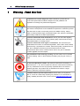
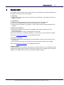
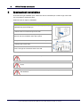
VPFlowTerminal
user manual
© 2013 Van Putten Instruments BV
MAN-VP-T5110-UK
Revision:2
Date:13-12-2013
www.vpinstruments.com
VPFlowTerminal user manual
© 2013 Van Putten Instruments BV
All rights reserved. No parts of this work may be reproduced in any form or by any means - graphic, electronic, or
mechanical, including photocopying, recording, taping, or information storage and retrieval systems - without the
written permission of the publisher.
Products that are referred to in this document may be either trademarks and/or registered trademarks of the
respective owners. The publisher and the author make no claim to these trademarks.
While every precaution has been taken in the preparation of this document, the publisher and the author
assume no responsibility for errors or omissions, or for damages resulting from the use of information
contained in this document or from the use of programs and source code that may accompany it. In no event
shall the publisher and the author be liable for any loss of profit or any other commercial damage caused or
alleged to have been caused directly or indirectly by this document.
Creation date: 13-12-2013 in (Delft)
Publisher
VPInstruments
Delft, The Netherlands
Contents
3
Table of Contents
1 Warning - Read this first
4
2 Introduction
5
3 Product overview
6
4 Quick start
7
5 Mechanical installation
8
6 Electrical connections
9
1 Connections
................................................................................................................................... 9
2 Electrical
...................................................................................................................................
overview
9
3 VPFlow
...................................................................................................................................
Scope connections
10
4 Analog
...................................................................................................................................
inputs
10
5 Ethernet
...................................................................................................................................
converter
11
6 Schemes
................................................................................................................................... 12
7 Display
13
1 Display
...................................................................................................................................
status icons
13
2 LCD
...................................................................................................................................
display
13
3 Data
...................................................................................................................................
Logger
13
4 Keypad
................................................................................................................................... 14
5 Menu
................................................................................................................................... 14
8 VPStudio software
17
9 Service
18
1 Softw
...................................................................................................................................
are and firmw are updates
18
2 Recalibration
................................................................................................................................... 18
3 Service
...................................................................................................................................
subscriptions
18
10 Specifications
19
11 Order information and accessories
20
12 Appendix A - Connection examples
21
13 Appendix B - Zero and Span calculation
22
3
4
1
VPFlow Terminal user manual
Warning - Read this first
Compressed air can be dangerous! Please familiarize yourself with the
forces under pressurized conditions. Respect the local guidelines and
regulations for working with pressurized equipment.
Gas flow through pipes follows certain physical laws. These physical laws
have serious consequences for the installation requirements. Familiarize yourself
with these laws to make sure that the product is installed correctly. Always
make sure that upstream length, downstream length, flow, pressure, temperature
and humidity conditions are within specifications.
Precision instruments need maintenance. Check your flow meter regularly
and make sure it remains clean. When polluted, gently clean the sensor using
demineralised water or cleaning alcohol.
Precision instruments need regular re-calibration. The VPFlowScope is
guaranteed for 24 months on manufacturing defects, when used in clean, filtered,
oil free and dry compressed air. However, when the air quality conditions are not
met, the re-calibration interval may become shorter than 24 months.
VPInstruments offers service contracts which cover a one year re-calibration,
firmware upgrades and minor repairs.
Not intended for fiscal metering or billing. Our flow meters are not certified
for fiscal metering. Laws on fiscal metering and billing may vary per country or
state.
Do not overestimate the results. The practical measurement uncertainty of
VPFlowScope is +/- 5%. Do not expect less than 5% measurement uncertainty
from any measurement as this is physically impossible due to the nature of
turbulent pipe flows. Our products are not intended to be used as a single
means to determine compressor capacity.
Feedback leads to product improvement. Please share your experience
with us, as we are continuously improving our products in our commitment to
quality, reliability and ease of use. Let us know via [email protected]!
© 2013 Van Putten Instruments BV | MAN-VP-T5110-UK | Revision:2 | Date:13-12-2013
Warning - Read this first
2
5
Introduction
Dear customer,
Thank you for purchasing the VPFlowTerminal. The VPFlowTerminal is a remote display for the
VPFlowScope product family, has a built-in data logger and provides input for 4 analog inputs.
Great products deserve great user manuals. We have done our best to make this user manual as
complete as possible. New users, please read it carefully to familiarize yourself with our products.
Experienced users can check out the Quick start chapter.
This manual is dedicated to:
VPT.5110.000
Do you like our products and this user manual? Tell others! Do you miss something? Let us know
via [email protected]!
© 2013 Van Putten Instruments BV | MAN-VP-T5110-UK | Revision:2 | Date:13-12-2013
6
3
VPFlow Terminal user manual
Product overview
The VPFlowTerminal is intended as remote display. It provides local read out on locations where the
VPFlowScope is placed in high or unreachable locations. The display provides read out for flow,
pressure, temperature, totalizer and up to 4 analog inputs.
To make the VPFlowTerminal even more complete, a 2 Million point data logger and Modbus to
Ethernet converter are integrated.
The VPFlowTerminal can be used in combination with the:
VPFlowScope probe Thermal Mass
VPFlowScope in-line Thermal Mass
VPFlowScope probe Differential Pressure
© 2013 Van Putten Instruments BV | MAN-VP-T5110-UK | Revision:2 | Date:13-12-2013
Product overview
4
7
Quick start
This chapter contains the basic steps to start using your VPFlowTerminal. Additional information on
all subjects can be found in the next chapters.
1. Unpacking
Unpack the box and check if all items are there and in good shape. A checklist with all items is
available on the box
2. Configuration
Connect the VPFlowScope sensor to the connector cap of the VPFlowTerminal
Power up the VPFlowTerminal and connect the USB cable to a computer
Configure inner pipe diameter, log intervals, 4..20mA inputs and other required parameters with
VPStudio
3. Mechanical installation
See the user manual for the best point of installation for this product. Make sure that all
specifications are met
4 holes are available to mount the VPFlowTerminal on the wall
Install the VPFlowScope. Installation guidelines can be found in it's manual. Read this carefully
See chapter mechanical installation for more detailed information.
4. Electrical installation
A cable for connecting the VPFlowScope is pre-assembled. Connect the connector cap to the
VPFlowScope
Apply 100-240 VAC to power up the device, the display will light up when power is applied
See chapter electrical connections for more detailed information.
5. Data recording
A data log session can be started by pressing the esc button and then enter. All parameters will be
logged with the default logging intervals. These logging intervals can be changed with the VPStudio
software. This software tool is also used to retrieve the recorded sessions
© 2013 Van Putten Instruments BV | MAN-VP-T5110-UK | Revision:2 | Date:13-12-2013
8
5
VPFlow Terminal user manual
Mechanical installation
First select the right installation point. Make sure that the VPFlowScope is within range of the cable.
It is not possible to extend the cable.
Follow the next six steps for installation.
1. Remove the silver strip at the left side by lifting it up with your
fingernails and pull it towards you
2. Remove the two screws and open the cover
3. Hold the VPFlowTerminal at the preferred position on the wall
and mark the four installation holes with a pencil
4. Lay the VPFlowTerminal aside and drill the marked points
5. Insert a jack in each hole
6. Hold the VPFlowTerminal in front of the drilled holes and
screw it through the connection holes to the wall
Do not install the VPFlowTerminal upside down
Do not install the VPFlowTerminal in an environment where fluids can leak onto the
device
Do not drill through the installation holes, use a pencil to mark the position holes and
drill afterwards
© 2013 Van Putten Instruments BV | MAN-VP-T5110-UK | Revision:2 | Date:13-12-2013
Mechanical installation
6
9
Electrical connections
Turn off power when the VPFlowTerminal is opened
The VPFlowTerminal has a pre-assembled cable for the VPFlowScope. The VPFlowScope in-line with
M12 8-pin connector can be connected to this cable directly. A connector cap with M12 8-pin
connector is used to connect the VPFlowScope probe models. A VPFlowScope with 5-pin connector
can not be connected.
A VPFlowScope needs to be connected to the VPFlowTerminal in order to work. It is not possible to
use the VPFlowTerminal without the VPFlowScope connected.
To access the inputs and outputs of the VPFlowTerminal, the case needs to be opened. Make sure
that it is tightened well to maintain the IP grade.
6.1
Connections
At the bottom of the VPFlowTerminal there are several connections as seen in the image below.
1. AC Mains inlet
2. Cable with connector cap for VPFlowScope
(pre-wired)
3. Optional cable inlet/outlet for VPFlowScope
RS485 bus.
4. Analog input 1
5. Analog input 2
6. Analog input 3
7. Analog input 4
8. Ethernet connector for VPFlowScope
9. USB connector
6.2
Electrical overview
1. AC Mains screw terminal
2. Power supply
3. Secondary fuse (2x)
4. VPFlowScope input screw terminal
5. VPFlowScope output screw terminal
6. RS485 Ethernet converter
7. Analog input (4x)
© 2013 Van Putten Instruments BV | MAN-VP-T5110-UK | Revision:2 | Date:13-12-2013
10
6.3
VPFlow Terminal user manual
VPFlowScope connections
VPFlowScope connection
The cable to the VPFlowScope is pre-wired. All
signals are available on the middle screw
terminal block. These signals can be used for
connection to a building management system
or Modbus chain.
RS485:
These terminals are available in pairs, and can
be used for RS485 networking. Use twisted
pair shielded cable, with two pairs. One pair for
A and B, and one lead of the other pair to
interconnect the 0 Volt wire.
4..20mA:
The 4..20 mA output of the VPFlowScope is
Active, which means that the VPFlowScope
powers the loop. For VPFlowScope only the
4..20 mA + is used. 4..20 mA - is not
connected.
6.4
Pin
Signal
1
Rx
2
0 Volt
3
Tx
4
4..20 mA signal, active
5
RS485 A
6
RS485 B
7
Not connected
8
+12...24 VDC
Analog inputs
Analog inputs
The VPFlowTerminal features 4 powered loop
analog inputs. Each input has a 24V supply
and a return input. The current signal is
measured within this loop
If the analog sensor requires a separate power
supply which means that it is not powered from
the loop, the 0 and 24V outputs can be used.
(150mA max)
© 2013 Van Putten Instruments BV | MAN-VP-T5110-UK | Revision:2 | Date:13-12-2013
Electrical connections
6.5
11
Ethernet converter
The VPFlowTerminal contains a built in Ethernet port. This port is based upon a Lantronix xport
module. In order to use this port, it needs to be configured and assigned with an IP address. The
application to configure the port can be downloaded from www.lantronix.com. Search for
deviceInstaller in the download area.
Xport configuration
Download and install deviceInstaller from the Lantronix website
Power up the VPFlowTerminal and connect an Ethernet cable to your computer.
Start deviceInstaller and click search. The Xport should be found.
When the port is not listed, assign a fixed IP address to your computer
Select the xport module and go to the tab "web configuration". Then click the green button to open
the configuration window. Log in with username "admin" and leave the password form empty.
Addressing an IP address
Select the option "network" in the menu. Here you can adjust the network settings of the xport.
Setting the baud rate
The xport converts the RS485 signal from the VPFlowScope to Ethernet. Therefore, the xport
needs to know what the communication parameters are. Click serial settings in the menu to
change. Make sure that the settings match the VPFlowScope settings.
Other options
All other options for the xport are pre-configured and may not be changed. Changing these
parameters may cause the converter to stop working.
Modbus communication
Once the port is installed, the VPFlowTerminal is ready to be used with Modbus. All VPFlowScope
parameters are available according the VPFlowScope manual. Note that the signal is Modbus RTU
over TCP.
VPStudio communication
For communication with VPStudio, a virtual COM port needs to be created as VPStudio does not
support IP communication.
A virtual COM port can be created with the CPR (COM Port Redirector) from Lantronix. This software
can be download at www.lantronix.com
Install and run the software and follow next steps:
Click the add/remove button above the list of all COM ports. Note: there may be inaccessible COM
ports in the list. These are reserved by your system and should be left alone.
Select an available COM port and click OK.
Click the "search for device" button. The CPR software will search for Lantronix devices connected
to the network. All found devices will appear in the device list below the COM ports.
Double click on the COM port you want to assign the device to and a new window will appear.
Leave these settings as is and right click on the device you want to connect to the port. Then
choose the option "add to settings". The IP address will appear with it's TCP port.
Clicking the save button will rise a new tab called [number] test. Go to this tab.
Click on the open button and the port will be tested. When all went well, the connection is in place
and can now be used.
NOTE: When the CPR software has issues, lower your firewall settings.
© 2013 Van Putten Instruments BV | MAN-VP-T5110-UK | Revision:2 | Date:13-12-2013
12
6.6
VPFlow Terminal user manual
Schemes
© 2013 Van Putten Instruments BV | MAN-VP-T5110-UK | Revision:2 | Date:13-12-2013
Electrical connections
7
13
Display
The display is used for real time read out of the VPFlowScope sensor inputs and the analog signals.
This chapter explains all functionality.
7.1
Display status icons
Some status icons show feedback on the meters' status. Below is a list with explanation
Icons
Description
Sensor module is properly connected and supplied with power
No communication with the sensor [Check external power when disconnected]
A blinking dot will indicate that a data session is active
2 rotating arrows indicate that there is communication with the computer
The display is locked. The menu can not be accessed
Memory indication. Each block indicates 20% of memory usage. The blocks start to
blink if the memory is more then 95% full
7.2
LCD display
The LCD display provides 3 rows for real time data. Each row can be configured in the menu by
selecting the desired parameter for this row.
Available options are listed in menu -> display.
7.3
Data Logger
The built-in data logger offers you 2 Million data points. Enough to measure all three channels 1 x per
second for more than a week. A little warning though: more data does not always lead to better
insight in savings! The analog inputs can also be stored in the data logger. The log interval for each
input can be set with the VPStudio software.
Use the following guidelines for the intervals
Application
Flow
Pressure
Temperature
Standard energy management application
5 min
5 min
5 min
Machine testing - quick fluctuations
1 sec
1 sec
1 sec
Audit - one week
10 sec
10 sec
5 min
Audit - one month
30 sec
30 sec
5 min
© 2013 Van Putten Instruments BV | MAN-VP-T5110-UK | Revision:2 | Date:13-12-2013
14
VPFlow Terminal user manual
Multiple sessions can be recorded. When a session is started, a separate session will be recorded.
It's not possible to append to an existing session.
When a power failure occurs during recording, the session will be stopped. When power is restored,
a new session will start automatically.
7.4
Keypad
The key pad contains 4 buttons to control the VPFlowTerminal
1
2
3
4
Menu / Enter
Used to enter the (sub)menu or to confirm a setting
Escape / Record Will start a data logging session when in the data acquisition screen.
Will return from a (sub)menu when not in the data acquisition screen
Button down
Navigate down in the menu
Button up
Navigate up in the menu
Special key functions
Lock display
In the main screen, press up and down simultaneously to lock or unlock the display. A lock
icon will appear in the right lower corner of the screen. The lock function will block keypad
functionality.
Clean re-boot.
Hold esc pressed when turning the power on. Use this option when a display will not start up
or if a session won’t stop. This can happen due to subsequent power failures at the moment
that the memory is almost full.
7.5
Menu
The menu is categorized into 3 main items which contain their own sub menu items. The complete
menu structure is shown below:
1. Settings
1. Display
2. Date and Time
3. Modbus address
4. Display dimtime
2. DAQ Sessions
1. New Session
2. Delete all
3. Advanced
1. Reset
© 2013 Van Putten Instruments BV | MAN-VP-T5110-UK | Revision:2 | Date:13-12-2013
Display
15
1 Settings
The settings menu can be used to change both functional parameters as display settings.
1.1 Display
The main screen of the display contains 3 rows to display measurement values. Via this menu
measurement values can be assigned to these rows. Available options in the menu are:
Measurand
Available units
Description
Empty
-
Leave this display row empty
Flow
mn/sec
Flow values are normalized: 0
degrees C and 1013.25 mbar
m3n/h
ln/min
CFM
m3/min
sfps
Pressure
Bar
Psi
Temperature
Deg C
Deg F
Totalizer
m3n
Gauge
Flow values are normalized: 0
degrees C and 1013.25 mbar
Analog inputs [1..4]
Analog inputs can be enabled
and configured with VPStudio
Custom
5 available units to be
configured with VPStudio.
Multiply an existing unit with a
user defined factor.
1.2 Date and Time
Adjust date and time settings. First enter the menu option and set the date with the key pad. The
date is formatted as: DD-MM-YYYY. After setting the date, confirm with enter and then enter the
time settings in format: HH:MM:SS, again confirm with enter. The new date will become active
immediately.
Date/time settings are kept actual by the real time clock until long power down. Date and time will
also be synchronized with the computer when used with VPStudio.
1.3 Modbus address
The Modbus address can be changed with this menu option. Use the up and down buttons to change
the number. Available numbers 1 – 247.
After setting the number press enter to save the address. The power of the attached VPFlowScope
needs to be cycled to activate the new address.
1.4 Display dimtime
The display backlight dimtime can be adjusted here. The default dimtime is set to 10 seconds. Other
Available options are:
Fading off. The backlight will remain on
5 till 30 seconds with steps of 5 seconds
© 2013 Van Putten Instruments BV | MAN-VP-T5110-UK | Revision:2 | Date:13-12-2013
16
VPFlow Terminal user manual
Confirming with menu will make this setting immediately active.
2 DAQ Sessions
The VPFlowTerminal contains a 2 Million point datalogger. Via this menu you can start and stop the
sessions or delete all present data.
2.1 Start session
The session will be started when you push the enter button after selecting this option. When the
session is started, the menu will close and the main screen will be shown. A blinking dot in the right
upper corner will indicate the running session. The menu will be blocked when a session is active.
The session can be stopped by pressing the esc button.
2.2 Delete all
All sessions will be deleted. It is not possible to delete just a single session.
3 Advanced
3.1 Reset
Reset the device. All peripherals will be reinitialized. This option is also needed when updating the
display firmware. Note: The Etnernet port and VPFlowScope sensor are not reset during this
sequence.
© 2013 Van Putten Instruments BV | MAN-VP-T5110-UK | Revision:2 | Date:13-12-2013
Display
8
17
VPStudio software
The VPFlowTerminal and its attached sensor can be read out and configured with the VPStudio
software. This software can be downloaded from www.vpinstruments.com.
In case of basic configuration and read out, use the free edition. If real time logging is required,
request a license code by our sales department.
A quick start is shown below, read the VPStudio manual for more information. This manual can be
downloaded from www.vpinstruments.com/downloads
Connect the VPFlowTerminal to the computer
The VPFlowTerminal can be connected to the computer with the USB connector. You can only
download data log sessions and configure the display. For configuration or read out of the sensor the
mains cable needs to be connected power up the attached sensor.
Install USB drivers
A driver needs to be installed for the USB interface. The driver might be installed automatically by
your windows system or need to be installed manually. All drivers are available on our website
www.vpinstruments.com/downloads.
Configure the VPFlowTerminal
Start the VPStudio software
In the left white window, right click to open the menu. Now click add device
Click the scan button to search for the right COM port. Select it and click add
Enter a name for the device
Select USB
Click add
VPFlowTerminal display read out
Click on the terminal icon to read out the display settings
The status tab provides general information
The installation tab is used to configure the settings
Click sessions below display to retrieve session data
VPFlowScope sensor read out
Click on the plus symbol to unfold the sensor option
Click on the sensor icon to read out the sensor settings
The status tab provides general information
The installation tab is used to configure the settings
© 2013 Van Putten Instruments BV | MAN-VP-T5110-UK | Revision:2 | Date:13-12-2013
18
9
VPFlow Terminal user manual
Service
The VPFlowScope attached to your VPFlowTerminal needs regular maintenance to ensure that the
product is functioning properly. Especially when the product is used for mobile air audits, we
recommend inspecting the instrument before and after every audit to ensure that the product has not
been damaged. For precision measurement equipment such as the VPFlowScope, a proper
maintenance program is key to reliable measurement results and a long product lifetime.
9.1
Software and firmware updates
News on software and firmware updates can be found on www.vpinstruments.com, or are provided by
your local re-seller. The USB interface is used for updating the firmware of the VPFlowTerminal.
Instructions on the update procedure can be found in a separate instruction leaflet, which is
distributed on request. Upgrading is only possible for authorized technicians, at own risk.
9.2
Recalibration
To keep your VPFlowScope in best shape, it needs recalibration. The recommended recalibration
date can be found in VPStudio, when you read out your VPFlowScope. Keep close eye on this date.
We advice annual recalibration.
9.3
Service subscriptions
VPInstruments offers several Service Subscriptions. Enrolling in the Service Subscription Program
helps you get the most out of your measurement equipment. We keep your equipment in excellent
shape, as we offer an annual re-calibration on our state of the art calibration equipment. With the
latest software releases and expert technical support, you will save time and money. We offer the
following programs:
-
Standard Service Subscription; Re-calibration, repair*, cleaning, firmware update and
warranty extension when serviced within 12 months subsequent intervals.
Full Service Subscription; Annual exchange of your flow meter. No service time! Have a fully
calibrated flow meter 24/7, 365 days a week!
* Repair within terms of usage, see general terms and conditions.
Improved software performance, innovative new product features, and technical support helps keep
you focused on what matters most for your company.
Benefits
- Annual calibrated and cleaned instruments
- Warranty extension
- Software- and firmware updates
- Live support and e-mail support by our skilled technicians
Consult your distributor for information about our service program.
© 2013 Van Putten Instruments BV | MAN-VP-T5110-UK | Revision:2 | Date:13-12-2013
Service
10
19
Specifications
Please always check the label of your product for the specifications.
Specifications are subject to change as we are continuously improving our products.
Please contact us to obtain the latest specification sheet.
Mechanical
VPT.5110.000
Housing
Ambient temperature
230mm x 130mm x 75mm 1.6 Kg
Painted Aluminum IP65
0..50°C
Electrical
Power supply
Primary fuse
Secondary fuses
100 - 240 VAC
1 Ampere
250 mili Ampere
Display
Technology
Back light
Memory
Liquid crystal
Blue with auto power save
2 Million point memory
Inputs and outputs
Analog output
Analog inputs
Serial IO
Ethernet
32 .. 122°F
VPFlowScope current / pulse output
4 x 4..20mA input
Modbus RTU
USB for configuration
Lantronix Xport converter for RS485
© 2013 Van Putten Instruments BV | MAN-VP-T5110-UK | Revision:2 | Date:13-12-2013
20
11
VPFlow Terminal user manual
Order information and accessories
VPT.5110.000
VPS.R150.P400.VPT.KIT
VPS.R150.P600.VPT.KIT
VPS.R150.P4DP.VPT.KIT
Accesories
VPA.5001.901
VPFlowTerminal
VPFlowterminal with VPFlowScope, probe length 400mm
VPFlowterminal with VPFlowScope, probe length 600mm
VPFlowterminal with VPFlowScope dP, probe length 400mm
Connector cap with M12, 8 pin socket. For VPFlowScope (dP)
sensor module in combination with VPFlowTerminal
VPStudio software
SFT.5003.300
SFT.5002.400
Licensed edition VPS&VPT
Full version
4..20mA Sensors
VPA.8000.2100
VPA.8000.2200
VPA.8000.2400
VPA.8000.2600
VPA.8000.21K5
VPA.8000.1003
VPA.8000.1006
VPA.8000.1013
VPA.8000.1016
VPA.8000.1020
VPA.8000.1030
VPLog-i AC current sensor 100A-rms
VPLog-i AC current sensor 200A-rms
VPLog-i AC current sensor 400A-rms
VPLog-i AC current sensor 800A-rms
VPLog-i AC current sensor 1500A-rms
Dew point sensor -100 … +20 (BSP)
Dew point sensor -100 … +20 (NPT)
Dew point sensor -40 … +60 (BSP)
Dew point sensor -40 … +60 (NPT)
Pressure sensor 0-16 bar abs BSP thread
Pressure sensor 0-16 bar abs NPT thread
© 2013 Van Putten Instruments BV | MAN-VP-T5110-UK | Revision:2 | Date:13-12-2013
Order information and accessories
12
Appendix A - Connection examples
VPFlowTerminal with VPLogI
VPFlowTerminal with VPFlowMate
VPFlowTerminal with additional VPFlowScope
© 2013 Van Putten Instruments BV | MAN-VP-T5110-UK | Revision:2 | Date:13-12-2013
21
22
13
VPFlow Terminal user manual
Appendix B - Zero and Span calculation
Configuration of the VPFlowTerminal for analog inputs
You need to configure the VPFlowTerminal via your personal computer, using VPStudio software.
There are three things to configure:
The name and prefix of the sensor
The logging interval for the sensor
The 4..20 mA scaling for the sensor
Current to power calculation
In this example we will explain how to calculate the power corresponding to the 4..20 mA output
value. Before we can do this we need some more data.
1. Measure the supply Voltage (! remember, this is a task for certified electricians)
2. Check the power factor of your motor. The power factor will be a number between 0.7 and 0.9, and
is assumed to be constant.
The formula to calculate the power is as follows, for a three phase motor:
This formula can be simplified:
Lets assume a cosinus(φ) of 0.7
For a 200 Amp current clamp, the Pmax (maximum power) is:
This number will correspond to 20 mA and this is the number to fill as span value.
0 kW will correspond to 4mA as this is the current level when there is no power being consumed.
This number can be filled in as zero value
So now you have configured all input you need. You can start logging now.
Setting the logging interval
The logging interval depends on what you would like to see. If you are interested in control system
behavior, you can set the logging interval to 1 second, and measure for a couple of days. If you would
like to see slow variations, for example the influence of daily production on the performance, you can
set the interval to once per minute. For see seasonal influence, a 15 minute interval provides enough
data to make the right analysis.
TIP: For flow, pressure and kW, we recommend to have identical intervals.
© 2013 Van Putten Instruments BV | MAN-VP-T5110-UK | Revision:2 | Date:13-12-2013
23
Notes
© 2013 Van Putten Instruments BV
www.vpinstruments.com
Measure
MAN-VP-T5110-UK
Revision:2
Date:13-12-2013
Monitor
Manage