1
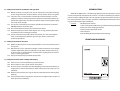
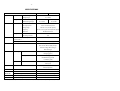
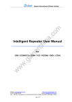
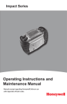
USER'S GUIDE
APOLLO S-120AM
●
● ! ●
STAND-ALONE INVERTER with
MPPT CHARGE CONTROLLER
-1-
SAFETY INSTRUCTIONS
CONTENT
SAFETY INSTRUCTIONS
INTRODUCTION
FRONT AND REAR PANEL
INSTALLATION AND OPERATION
TROUBLESHOOTING
SPECIFICATIONS
1
3
3
6
7
8
Please read and follow this user’s manual carefully and completely.
Important : Please keep this user’s manual for later reference. It consists of
Introduction, Front and Rear Panel, Installation and Operation, and
Troubleshooting.
If the inverter does not operate properly and you cannot solve the problem using
the troubleshooting information in this user’s manual, please contact LEONICS local
distributors, LEONICS Service Center, send e-mail to [email protected] or visit
www.leonics.com.
To help you much more quickly when contact us, please record the
following information:
LEONICS APOLLO model : ____________________________
Serial number
: ____________________________
Purchased date
: ____________________________
Purchased from
: ____________________________
WARNING!
Risk of electric shock, DO NOT remove cover. No user serviceable part
inside, please refer servicing to qualified service personnel.
1.1 Electrical Safety
1.1.1 Do not work alone where there are electrically hazardous conditions.
1.1.2 Contact with live conductors will cause burns and dangerous electric shock.
1.1.3 Only qualified electricians should install or service this unit, PV panel and
batteries.
1.1.4 Properly install and ground (
) the equipment in accordance with the
instruction manual.
1.1.5 Periodically check your cable, terminal and power source to make sure that
they are in good condition.
1.1.6 To reduce risk from electric shock , disconnect all power source before
connecting / disconnecting the batteries or loads or when maintaining or
servicing this unit.
-2-
1.2 Safety instruction for installation and operation
1.2.1 Before installing or using this unit, read all instructions and caution markings
on the charge controller, PV panel, battery and all sections of this user guide.
1.2.2 Install this unit in a temperature and humidity controlled indoor area with
adequate air flow and away from chemical particles or flammable substances .
Avoid installing the unit near radio transmission station, heat dissipation equipment and direct sunlight.
1.2.3 This unit has ventilation grills. Ensure that sufficient ventilation is provided.
DO NOT block the ventilation grills.
1.2.4 Use insulated tools to reduce your risk of electric shock.
1.2.5 Remove all jewelry or other metal objects such as rings, necklace, bracelets
and watches when installing this product.
1.2.6 Do not install this unit directly above the batteries or in the same compartment as vented batteries. Batteries generate gas, which is corrosive to
electronic equipment.
1.3 Safety instruction for PV panel
1.3.1 Before installation, please read instruction books or user's manual for PV panel
and system.
1.3.2 Whenever PV array is exposed to sunlight, a shock hazard exists at the output
cables or exposed terminal. To reduce the risk of shock, disconnect the array,
or cover it with an opaque cloth or material before making electrical connections or servicing the system.
1.3.3 Ensure correct polarity connection of PV panels.
1.4 Safety Instruction when working with battery
1.4.1 Ensure the area around the battery is well ventilated.
1.4.2 Never smoke or allow a spark or flam near battery.
1.4.3 Be extra cautions to reduce the risk of dropping a metal tools onto battery. It
might spark or short circuit battery or other electrical parts that may cause an
explosion.
1.4.4 Remove all metal items, like rings, bracelets and watches when working with
batteries.
1.4.5 Have someone within range of your voice or close enough to come to your aid
when you work near battery.
-3-
INTRODUCTION
APOLLO S-120AM series is a compact high efficiency solar charger built-in stand alone
inverter controlled by microprocessor. Inverter is used for transforming DC power to AC
power in order to supply AC loads. Solar charger will charge battery when DC power from
PV is detected with 3 stages charging. And built-in MPPT (Maximum Power Point Tracking) to maximize power generated by PV.
Features :
- Microprocessor Control
- Short circuit, Overload, Overcharge and Overdischarge Protection
- Quick and smart charging for battery
- Reverse polarity protection for PV
- LED indication
- Built-in MPPT (Maximum Power Point Tracking)
FRONT AND REAR PANEL
-4-
-5-
Table 2 : Indicator Light and Battery Status
STATUS
Full battery
Medium battery
Low battery
first indicator
(green)
lit
off
off
second indicator
(yellow)
off
lit
off
third indicator
(red)
off
off
blink
Table 3 : Indicator Lights and Inverter Status
STATUS
Inverter is operating
Over temperature
Low battery alarm
Overload alarm
Inverter fault alarm
INVERTER indicator (green)
lit
-
ALARM indicator (red)
off
slow blink
blink
quick blink
lit
3.1 Front Panel
3.1.1 SOLAR CHARGER show solar charger and battery status.
3.1.1.1 BOOST CHARGE :
APOLLO S-120AM series is operating in
boost charging mode.
3.1.1.2 CHARGING
:
APOLLO S-120AM series is charging the
battery.
3.1.1.3 Battery Level
:
The indicator light show the full, medium
and low battery level.
3.1.2 INVERTER show inverter status.
3.1.2.1 INVERTER NORMAL:
Inverter is operating.
3.1.2.2 ALARM
:
The APOLLO S-120AM series is in abnormal
conditions.
3.2 Rear Panel
Table1 : Indicator Lights and Charging Status
STATUS
Bulk charging
Boost charging
Float charging
Not operating
BOOST CHARGE indicator (green) CHARGING indicator (green)
off
lit
blink (on 1.4 sec., off 0.2 sec.)
blink (on 1.4 sec., off 0.2 sec.)
off
blink (on 0.8 sec., off 0.8 sec.)
off
off
3.2.1 POWER SWITCH Switch for turn on-off APOLLO S-120AM series.
3.2.2 FUSE A safety component for protect system from overload or battery short
circuit.
3.2.3 TERMINALS The terminal for connecting to ground, PV and battery.
(see Installation and Operation)
3.2.4 OUTPUT Plug receptacles directly connect to AC loads.
-6-
-7-
INSTALLATION AND OPERATION
4.2 Start up Procedure
4.2.1
4.2.2
4.2.3
4.2.4
Turn off all AC loads that connected to APOLLO S-120AM series.
Turn on battery breaker and PV circuit breaker respectively.
Turn on the power switch after the INVERTER indicator is lit.
Turn on AC loads that connected to APOLLO S-120AM series.
4.3 Shut down Procedure
4.3.1 Turn off all AC loads that connected to APOLLO S-120AM series.
4.3.2 Turn off the power switch.
4.3.3 Turn off PV circuit breaker and battery circuit breaker respectively.
Battery
Circuit Breaker
(40A 2P)
PV Circuit
Breaker
(16A 2P)
BATTERY
Figure 1.
Sample of connection diagram is shown above. Before installing or using this unit,
read all instructions and caution markings on this unit, PV panel, batteries and all sections of this user’s guide.
For your safety, all cables should be wired in the suitable size conduits.
4.1 Installation
4.1.1 Turn off Power switch and turn off all breaker.
) position by using copper
4.1.2 Connect grounding wire at the PE/EARTH (
wire sizing in Figure 1.
4.1.3 Connect battery cable from positive (+) battery to positive (+) terminal at rear
panel and negative (-) battery to negative (-) terminal at rear panel through
battery circuit breaker.
4.1.4 Connect PV cable from positive (+) PV array to positive (+) terminal at rear
panel and negative (-) PV array to negative (-) terminal at rear panel through
PV circuit breaker.
4.1.5 Plug-in AC loads at AC Output receptacle.
TROUBLESHOOTING
If the inverter does not operate properly and you cannot solve the problem using
the troubleshooting information in this users manual, please contact your LEONICS local
distributors, LEONICS Service Center, send e-mail to [email protected] or visit
www.leonics.com.
SYMPTOMS
ALARM indicator is lit
(red).
CAUSE
SOLUTION
- Check AC cable connected
- Short circuit of AC loads.
to APOLLO S-120AM series
- APOLLO S-120AM inverter is
- Consult service center.
fault.
INVERTER indicator is lit,
but there is no AC power
from AC outlet.
The inverter is overloaded and - Turn off AC loads and inverter
follow item 4.3. Disconnect
shutdown itself (overload
some loads, the restart again
shutdown condition).
follow item 4.2.
The power switch is on
but inverter does not
operate or INVERTER
NORMAL is off.
Battery voltage is too low
until the inverter can not
operate (Low battery shut down condition.
- Turn off the power switch
and restart again and wait
until the INVERTER NORMAL
indicator is lit or the inverter
start battery charging.
ALARM indicator blink
slowly.
Over temperature condition
- Ensure that sufficient ventilation is provided.
- Ensure that the ventilation fan
at the rear side work properly.
-8-
SPECIFICATIONS
MODEL
INPUT
S-120A-M37
Inverter mode
Charger mode
OUTPUT
Inverter mode
Nominal voltage
12 Vdc
Voltage range
10 - 16 Vdc
PV maximum voltage
70 Vdc
92 Vdc
MPPT tracking voltage
26 - 70 Vdc
40 - 92 Vdc
Power continuous
150 VA / 150 Watt
Max. surge power
200% of continuous power
Voltage range
Charger mode
220 Vac ± 3% (230 Vac option)
Frequency
50 Hz ± 0.1% (crystal control) (60 Hz option)
Wave form
Modified sine wave
Nominal
Max. charge current
SYSTEM
S-120A-M59
Inverter maximum efficiency
12 Vdc
10 A
> 80%
at full load Pf.= 1
Low battery disconnect
PROTECTION
< 10.3 - 11.0 Volt pre-adjust
Over temperature / Overload /
Short circuit / Reverse (PV) polarity /
Transient voltage / Over charge /
Over discharge
INDICATOR
Solar Charger
Status
Boost charge (green)
Charging (green)
Battery level
Full Battery (green)
Medium Battery (yellow)
Low Battery (red)
Inverter
Status
Inverter normal (green)
Alarm (red)
ALARM
LED
Low battery / Overload / Short circuit /
VENTILATION
Fan
Automatic control
OPERATING
Temperature
CONDITION
Relative humidity
Over temperature
DIMENSION
W x H x D (cm.)
WEIGHT
Approximate in kg.
0 - 45°C
0 - 95% (non - condensing)
16.5 x 29.5 x 9.6
5.5
Continuous product development is our commiment. In that manner, the above specifications may be change without prior notice.