1
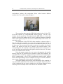
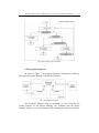
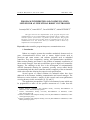
U.P.B. Sci. Bull., Series C, Vol. 75, Iss. 4, 2013
ISSN 2286 – 3540
PROGRAM INTERPRETER AND COMMUNICATION
SERVER FOR AN INDUSTRIAL ROBOT CONTROLLER
Laurenţiu DUCA1, Anton DUCA2, Cornel POPESCU3, Adrian PETRESCU4
This paper describes the implementation of the program interpreter and
communication server for a wafer handling robot controller. This is a complex robot
controller software system with a very flexible operator interface. The program
interpreter executes the robot programs which are transmitted by the user via the
communication server. The work is done by a modular system in which every
component has a strictly defined role.
Keywords: robot controller, program interpreter, communication server
1. Introduction
Robots are complex systems that combine mechanical elements such as
gears, electromechanical devices such as motors, digital circuits such as
processors and smart sensors, and software programs such as embedded
controllers. They have computation, sensing, and communication capabilities.
Robot motion planning and control is the problem of automatic construction of
robot control strategies, from task specifications given in high-level, human-like
language. The challenge in this area is the development of computationally
efficient frameworks allowing for systematic, provably correct control design
accommodating both the robot constraints and the complexity of the environment,
while at the same time allowing for expressive task specifications.
Several aspects of control solutions for industrial robots have been
addressed in the literature including communication and control strategies. The
References section includes a sample of this research and recent publications
covering advances in this area include [1], [2], and [3].
The application presented here is part of an automated system which may
be programmed to make all the possible movements of a robot from the
1
Assistant professor, Automatics and Computers Faculty, University POLITEHNICA of
Bucharest, e-mail: [email protected]
2
Lecturer, Electrotehnics Faculty, University POLITEHNICA of Bucharest, e-mail:
[email protected]
3
Professor, Automatics and Computers Faculty, University POLITEHNICA of Bucharest, e-mail:
[email protected]
4
Professor, Automatics and Computers Faculty, University POLITEHNICA of Bucharest, e-mail:
[email protected]
36
Laurenţiu Duca, Anton Duca, Cornel Popescu, Adrian Petrescu
semiconductor industry who manipulates silicon wafers between different
machine tools. The system is shown in figure 1.
Fig.1. The robot-controller system
The system has three parts: the SHR-3000 industrial robot [4], the FTC1018 robot controller [5], and ROBOPAK software package - used to be the
interface for the system user. The industrial robot SHR-3000 is a 3 axis robot
made for silicon wafer handling and is used for producing industrial equipment
and for wafer quality inspection. It can move simultaneously on all the axes. For
more info, see [4].
The architecture of the FTC-1018 robot controller is shown in figure 2.
The role of the robot controller is to execute the programs made by the user in
order to control the movements of the robot, here the SHR-3000 robot, on each of
the three axes. The movement of the robot on each axis is made by the electrical
motors. The position on each axis is shown by the optical encoder of the
corresponding axis. The controller commands the hardware driver of the motor on
an axis and reads the position from the optical encoder of that axis. The motor
drivers are controlled via the ISA bus.
Using the remote computer, the user creates robot programs and transfers
them by using the FTP protocol to the controller’s single board computer. The
user handles the controller by command messages sent and received by using the
RS232 communication or the TCP/IP communication modules which transmit
them to the Engine Manager. Those commands are of type: execution, simulation,
pause, restart, stop-program, reboot controller, send position.
The Engine Manager supervises the well functionality of the controller. It
is an intermediate module for all the modules in the controller functionality flow.
All the commands from the software modules go to the Engine Manager (except
transmit position command) which routes them to the destination module.
Program interpreter and communication server for an industrial robot controller
37
Fig.2. FTC-1018 robot controller
The Program Interpreter compiles the user's robot programs and executes
them. The Program Interpreter uses the Backend process for controlling the robot
movements and also for their simulation. It executes user commands like stop,
pause, restart execution of the user program and transmit robot position. The
messages between the Program Interpreter and Communication modules pass via
the Engine Manager.
The messages that show the state of the controller are shown on the LCD
screen. This is made by using the LCD Controller Communication module. The
LCD is controlled via the ISA bus.
The software modules written by the authors are the Communication
modules, the Engine Manager and the Program Interpreter. The language used is
the C language.
2. The controller management
The Engine Manager module’s role is to start the modules, monitor the
state of the modules, handle errors and supervise the good functionality of the
controller. The functionality of the Engine Manager is shown in figure 3.
The controller starts-up with the creation of the Engine Manager. Then are
created the software modules communication queues and the processes
38
Laurenţiu Duca, Anton Duca, Cornel Popescu, Adrian Petrescu
Communicater, Interpreter (Program Interpreter) and Backend. Now, the modules
are ready to handle the user requests and the main execution flow is started up.
When no command is arrived from the user, the Engine Manager is idle. It
can receive messages from the Interpreter or from the Communicater. The input
errors are fatal errors because we assume no errors come at communication
between modules.
Fig.3. The Engine Manager’s module workflow
The program shut down implies destroying all the modules, which is made
after checking that the robot does not move in any way. After program shut down,
the system can be rebooted by the user by pressing the reset button.
When the Interpreter fails to compile a user program, or it ends the
execution of the user program, requests its reset from the Engine Manager. The
Interpreter’s reset is done by killing the Interpreter process and starting a new one.
If the Interpreter wants to send a message to the user like the robot position or
program compilation error, then the Engine Manager transmits it to the
Communicater.
Program interpreter and communication server for an industrial robot controller
39
The Communicater may send to the Interpreter an information message
(for
example,
user
disconnected)
or
a
command
message
(run/simulate/wait/resume program, position reporting on/off). In this case, the
Engine Manager sends this message to the Interpreter.
3. The communication server
The communication server makes the link between the controller and the
user remote workstation (Remote PC). In figure 4 is shown the structure of the
communication server (also called Communicater).
Fig.4. The communication server
The communication manager handles all the communication server
activity. It takes messages from the user or Engine Manager and places them from
one to another. The Communicater must always be ready to receive messages
from the user remote workstation even when it wants to transmit messages to the
user. Input from the user remote workstation is taken with the Receiver (Listener)
process. The Listener takes messages from the user workstation and sends them to
the communication manager.
The functionality of the communication manager is described in figure 5.
The communication manager waits for input (blocking read) and when it receives
a packet, it first checks for input errors. If no error occurred and the packet is from
the Engine manager then it will send it to the user remote workstation. If the
packet comes from the Listener and it is not a disconnect request or a reset request
then it will send the packet to the Engine manager.
40
Laurenţiu Duca, Anton Duca, Cornel Popescu, Adrian Petrescu
Fig.5. The communication manager workflow
The functionality of the Listener process is described in figure 6. The
Listener process permits the user to disconnect and reconnect. It makes a blocking
listen in waiting for a message from the user client or for a connection request.
If the user wants a new connection, then the Listener will send to the
communication manager a reset request and the connection will be served. If a
new packet arrives and it is not too small, then the Listener will send the packet to
the communication manager.
In this version, the user must be in the same LAN network as the
controller. In future versions there are planned message encryption between the
user and controller and authentication of the user when connecting to the
controller.
Program interpreter and communication server for an industrial robot controller
41
Fig.6. The Listener process workflow
4. The program interpreter
As shown in figure 7, the program interpreter (Interpreter) is made by
three parts: Interpreter Manager, Compiler and Executer.
Fig.7. The program interpreter
The Interpreter Manager waits for commands to arrive from the user
remote computer via the Engine Manager. The command from the Engine
Manager may be to set some parameters (like animating the robot movement) or
42
Laurenţiu Duca, Anton Duca, Cornel Popescu, Adrian Petrescu
execution or simulation of a new program. When the command is to execute a
user defined robot program, the Interpreter Manager asks the Compiler to compile
the program into an internal structure recognized by the Executer and then request
the Executer to run the program. At the end of the execution, the Interpreter will
clean up memory and exit and the Engine Manager will create another Interpreter
process. The program execution is shown in figure 8. The instructions are
executed sequentially one by one until the end of the program. If at the execution
of some instruction, an error appeared, then the execution ends and the error will
be signalized to the user remote client via the Engine Manager. Between the
execution of two consecutive instructions, the Executer verifies if a new command
has arrived from the user. In the case that the new command is to end program or
execute new program, the current execution stops; otherwise, if the command is to
set up robot position reporting or wait/resume program, the command will be
executed, and then the program continues with the next instruction.
Fig.8. The Executer workflow
The user programs are written in the Ferroeng language, which is a
language defined by the authors and its grammar is similar to the C language. For
more info, consult [6].
Program interpreter and communication server for an industrial robot controller
43
5. Conclusion
The implementation of the Engine Manager as a separated module and
process brings advantages and disadvantages. The main advantage is that in any
of the states of a dedicated module - for example if the Interpreter would be
executing the user program – there is the Engine Manager who is available to
receive messages from any module and control the errors and unpredictable
situations that might appear. This way, the Engine Manager controls connecting
and disconnecting of the user remote client, the end of the execution of the user
defined robot program (which implies Interpreter reset), and other similar
situations. The main disadvantage is that the messages between two distinct
modules, for example the Interpreter and the Communicater are delayed by
passing through the Engine Manager. So, in the time that the robot is executing a
movement – the BackEnd process needs almost all of the processor resources for
the motion control algorithm. That’s why, the sending of the position to the
master computer by intermediating the Engine Manager may conduce to less
resources being available for the BackEnd process. This can be avoided by direct
sending of the position reporting from the BackEnd to the Communicater.
An alternative to implement the Interpreter module in other part than the
controller - and by this way, to free up some space on the controller - was to put it
on the user remote workstation. But then, the execution of the instructions
specifics to robot movement would had less control of the robot then it has now as
being close to the robot drivers. If only the Interpreter’s Compiler module would
have been put on the user remote workstation, then a solution to serialize the
compiled code of the user programs should be imposed, but this is too complex.
In this version, the user must be in the same LAN network as the
controller. In future versions there are planned message encryption between the
user and controller and authentication of the user when connecting to the
controller.
The user programs have a very simple structure, being the equivalent in C
of the main procedure. The authors did not include procedures and functions to
the Ferroeng robot programming language. That made a simpler program
interpreter. In the implementation of the lexical analyzer and parser it were used
tools like bison and flex, tools which made the implementation of the Interpreter
easier. Compiling the user programs is made by a single pass through the program
text. In future developments there are planned optimizations of the compiler.
The grammar of the user programming language is similar to ANSI C.
This model has lot of advantages like conflicts elimination and the fact that the
operator priorities are already established by the C language. The language covers
all the movements that a 3-axis robot can made. The movement of the robot in a
fixed Cartesian point can be made – at the level of the user program instruction -
44
Laurenţiu Duca, Anton Duca, Cornel Popescu, Adrian Petrescu
both by serializing the movements on each axis or by parallelizing the movements
on all robot axes at the same time. The portability of the programs on different
robots is made by the fact that the robot programming language offers instructions
that works with the Cartesian coordinate system.
REFERENCES
[1] S. Mokaram, "Mobile robots communication and control framework for USARSim",
Intelligent and Advanced Systems Conference (ICIAS), 2012
[2] S. Arias, A. Nègre, N. Turro, "Evolution of the robotic control frameworks at INRIA RhôneAlpes", Control Architectures of Robots (CAR11), Inria, 2011
[3] K. Kozłowski, “Robot Motion and Control”, Control and Information Sciences, Springer, 2011
[4] A.Twanjing, N.Tsuawei, “The SHR-3000 robot user manual”, Jel Press, 2008
[5] C.Stanciu, L.Duca, “FTC-1018 robot controller user manual”, FerroTech manuals, 2010
[6] M.Stanciu, L.Duca, “The Ferroeng language reference manual”, FerroTech manuals, 2010