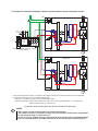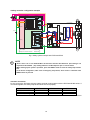
1
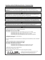
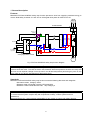
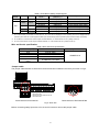
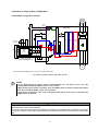
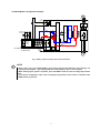
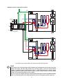
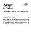
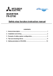
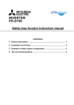
nnti INVERTER FR-E700-SC(-EC)(-NA)/NF/NC Safety stop function instruction manual CONTENTS 1. General description........................................................................... 2 2. Installation and wiring ...................................................................... 3 3. Example of safety system configuration ........................................ 6 4. Test and checking failure ............................................................... 10 5. Safety parameters of FR-E700-SC/NF/NC ..................................... 12 Compliance with the EU Machinery Directive – Functional Safety WARNING Any misuse of safety function could lead to personal injury or death, property damage, or economic loss. To ensure that the system complies fully with requirement of safety, make a system-level risk assessment. Mitsubishi Electric Co. cannot assume responsibility for any system to comply with safety directive. CAUTION The information of this manual is merely a guide for proper installation. Mitsubishi Electric Co. cannot assume responsibility for the compliance or the noncompliance to any code, national, local or otherwise for the proper installation of this equipment. A hazard of personal injury and/or equipment damage exists if codes are ignored during installation. WARNING To avoid an electric shock hazard, verify that the voltage on the bus capacitors has discharged before performing any work on the drive. Measure the DC bus voltage at the P(+) and N(-) terminals or test points (refer to your drive’s User Manual for locations and discharging time). The voltage must be zero. WARNING The safety stop function do not isolate electrically between drive and motor. To avoid an electric shock hazard, disconnect/isolate power to the drive and verify to ensure that the voltage is zero before performing any work on the motor (refer to your drive’s User Manual for discharging time). CAUTION ・FR-E700-SC/NF/NC which has the following SERIAL number are compatible with ISO13849. <FR-E700-SC/NF/NC series of Japanese specifications> FR-E700-SC: F or later FR-E700-NF: E or later FR-E700-NC: Three-phase 200V class 0.1K to 0.75K: C or later Three-phase 200V class 1.5K to 3.7K/11K/15K: B or later Three-phase 200V class 5.5K/7.5K: D or later (Three-phase 400V class and single-phase 200V class are all compatible.) <FR-E700-SC series of NA, EC specifications> Compatible for all models. ・Diodes are installed to S1 and S2 terminal of the following FR-E700-SC/NF/NC to block undesirable current. <FR-E700-SC/NF/NC series of Japanese specifications> FR-E700-SC: Manufactured in November 2010 or later FR-E700-NF: Manufactured in December 2010 or later FR-E700-NC: Three-phase 200V class and single-phase 200V class: Manufactured in November 2010 or later Three-phase 400V class: Manufactured in October 2010 or later <FR-E700-SC series of NA, EC specifications> Manufactured in August 2010 or later Check the SERIAL number indicated on the inverter rating plate or package. Rating plate example Symbol Year Month Control number SERIAL (Serial No.) The SERIAL consists of one symbol, two characters indicating production year and month, and six characters indicating control number. The last digit of the production year is indicated as the Year, and the Month is indicated by 1 to 9, X (October), Y (November), and Z 1 1. General description Features Mitsubishi FR-E700-SC/NF/NC safety stop function prevents a drive from supplying rotational energy to motors. Dual safety channels ‘S1’ and ‘S2’ cut off the gate-drive power for IGBT to turn off. FR-E700-SC/NF/NC R/L1 S/L2 T/L3 RUN or Y0 (SAFE2) SE IGBTs +24V PC Fuse CPU CPU Gate Driver Gate Driver G G RESET S1 S2 Emergency stop button Safety relay module / Safety programmable controller U V W IM Fig.1 FR-E700-SC/NF/NC safety stop function diagram WARNING Disconnecting the power to the gate driver by the safety stop function does not isolate electrically between drive and motor. To avoid an electric shock hazard, disconnect power to the drive and verify that the main circuit capacitor voltage is zero (across P and N terminals) before performing any work on the motor (refer to your drive’s User Manual for discharging time). Standards Mitsubishi FR-E700-SC/NF/NC safety stop function meets the following directives and categories. ISO13849-1:2008 Category 3/PLd IEC62061:2005 / IEC61800-5-2:2007 / IEC61508 SIL2 IEC60204-1:2006 / IEC61800-5-2:2007 Stop category 0 WARNING The misuse of safety function leads to personal injury or death, property damage, or economic loss. To ensure that the system complies fully with requirement of safety, make a system-level risk assessment. Mitsubishi Electric Co. cannot assume responsibility for any system to comply with safety directive. 2 2. Installation and wiring CAUTION The following information is merely a guide for proper installation. Mitsubishi Electric Co. cannot assume responsibility for the compliance or the noncompliance to any code, national, local or otherwise for the proper installation of this equipment. A hazard of personal injury and/or equipment damage exists if codes are ignored during installation. CAUTION Ensure the safety relay unit and the FR-E700-SC/NF/NC unit is mounted closely in enclosure meeting IP54 and all interconnection wiring is short and protected against open and short circuit faults. Refer ISO/IEC13849-2. Installation Mitsubishi FR-E700-SC/NF/NC safety stop function should be used under following condition and environment. Table.1 The condition and environment for using safety stop function Item Temperature Operation range Storage Ambient humidity Vibration Altitude Atmosphere Over voltage category Pollution degree Mounting Condition -10ºC to +50ºC (non-freezing) -20ºC to +65ºC 90%RH maximum (non-condensing) 5.9m/s2 or less maximum 1000m above sea level Indoors (without corrosive gas, flammable gas, oil mist, dust and dirt etc.) II or less II or less wall mounting / vertical orientation CAUTION In order to meet safety stop, an approved safety relay unit to ISO13849-1/EN954-1 safety category 3 or better shall be used in conjunction with FR-E700-SC/NF/NC as shown in example. In addition, all other components with in the safety stop loop shall be ‘safety approved’ types. WARNING To avoid an electric shock hazard, insert the magnetic contactor (MC) between power source and drive. Open the contact of MC and keep away from drive for discharging time (refer to your drive’s User Manual for information) before performing any work on the drive. And verify that the voltage on the bus capacitors has discharged before Measure the DC bus voltage at the P(+) and N(-) terminals or test points (refer to your drive’s User Manual for locations). The voltage must be zero. CAUTION To avoid systematic faults, a test even for faulty demands of the safety function has to be performed in order to check the correct function of the monitor signal. This test shall be carried out at system installation, any software changes, parameterization changes, and/or at least once per year. Refer to ‘4. Test and checking failure’. 3 Wiring The safety related terminals are described in Table.2 and Table.3 Table.2 The safety related terminals Terminal Symbol S1 S2 PC RUN or Y0 (SAFE2) SE Rating *2 Description Input resistance: 4.7kΩ Input Current : 4 to 6 mA (In case of shorted to PC) Input Voltage : 21 to 26.5 V For input of safety stop channel1. S1-PC is Open: In safety stop mode. Short: Non safety stop mode. For input of safety stop channel2. S2-PC is Open: In safety stop mode. Short: Non safety stop mode. Common terminal for S1,S2 signals. *PC is connected to 24V power source through diode and fuse. As output for failure detection and alarm. RUN terminal type is ‘Open collector output’. RUN or Y0-SE is OFF(Open): Detect failure or Alarm. ON(Close): No failure detected. Attention: To use RUN terminal or Y0 terminal for monitor output of failure detection, Pr. 190 should be set "81" (Safety monitor 2). Note: This terminal cannot be used to output safety outputs in a safety system. This terminal can be used for alarm or to prevent restart only, no other safety function. Common terminal for RUN terminal and Y0 terminal. As output for failure detection. A,C terminal type is ‘Relay output’. A-C is OFF(Open): Detect failure or Alarm. ON(Close): No failure detected. A, C *1 (SAFE2) Output Voltage 22V to 26.5V Output Current : 100mA max. Load: 24VDC/0.1A max. Voltage drop: 3.4V max. (In case of ‘ON’ state) Attention: To use A,C terminal for monitor output of failure detection, Pr. 192 should be set "81" (Safety monitor 2). Note: This terminal cannot be used to output safety outputs in a safety system. This terminal can be used for alarm or to prevent restart only, no other safety function. *1 The relay terminal is equipped for FR-E700-SC. *2 Specifications for conforming safety standards. 4 Load: 30VDC/0.3A max. Input power OFF ON S1-PC S2-PC - - Short Short Open Open Short Open Open Short Table.3 Truth table of Safety related signals Internal safety RUN, Y0-SE or A-C circuit *1 (SAFE2 ) *2*3 OFF(Open) No failure ON(Close) Failure OFF(Open) No failure ON(Close) Failure OFF(Open) N/A OFF(Open) N/A OFF(Open) Inverter operation state Drive shutoff (Safe state) Drive enable Drive shutoff (Safe state) Drive shutoff (Safe state) Drive shutoff (Safe state) Drive shutoff (Safe state) Drive shutoff (Safe state) "N/A" denotes a condition where circuit fault does not apply. *1 At an internal safety circuit fault, one of E.SAF, E.6, E.7, and E.CPU is displayed on the operation panel. SA is displayed on the *2 To use RUN or Y0 terminal for monitor output of failure detection, Pr. 190 should be set "81" (Safety monitor 2). *3 To use A,C terminal for monitor output of failure detection, Pr. 192 should be set "81" (Safety monitor 2). operation panel while S1 and S2 signals are both open and the safety function operates (without internal safety circuit fault). Wire and ferrule specification Table.4 Wire and ferrule specification 2 Wire size (mm ) 0.3 / 0.5 0.75 1 1.25 / 1.5 0.75 (combined 2 wire) * Ferrule with insulation collar * AI 0,5-10WH AI 0,75-10GY AI 1-10RD AI1,5-10BK Crimping tool name * CRIMPFOX 6 AI TWIN 2 X 0,75-10GY Ferrules and tools are distributed by Phoenix Contact. Jumper cable The jumper cable between S1,S2 and PC terminal has been installed in the factory as shown in Fig.2. 10 2 5 4 RUN FU SE S1 S2 PC *2 *1 FM RES RL RM RH SD SD STF STR A B C +24 SD S1 S2 PC Y0 SE *1 Terminal AM for FR-E700-SC-EC and FR-E700-SC-NA. *2 Terminal PC for FR-E700-SC-EC and FR-E700-SC-NA. Terminal block of FR-E700-SC Terminal block of FR-E700-NF/NC Fig.2. Short wire Before connecting safety input wire to S1,S2 and PC terminal, remove this jumper cable. 5 3. Example of safety system configuration ●FR-E700-SC configuration example RUN (SAFE2) RESET R/L1 S/L2 T/L3 FR-E700-SC SE START STF STOP STOP S1 CPU Emergency stop button +24V X0 COM0 X1 COM1 XS0 XS1 Z00 Z10 Z20 CPU Gate Driver Internal Safety Circuit IGBTs S2 G DC 24V Gate Driver G K1 K2 24G +24V Z01 Safety relay module MELSEC QS90SR2SN-Q Z11 Z21 PC Fuse PC* U V W IM * If the control logic is SINK logic, the common terminal is terminal SD. Fig.3 Safety system example with FR-E700-SC NOTE ・To use RUN terminal for monitor output of failure detection, Pr. 190 must be set to "81". This setting makes the RUN-SE output to open in case of failure. ・When starting up the system’s operation, press the RESET switch to reset the safety stop function first, then turn ON the START switch to run the motor. ・In the above configuration, after reset of emergency stop button, drive will be in safe-state until RESET switch is pressed. CAUTION To prevent restart in case of recovering from input power loss of drive, 3-wired connection for START/STOP control is recommended. In case of 2-wire connection and using latching type switch to short between STF and SD/PC for starting, ensure the compliance with safety requirement for the restarting when the drive recover from input power loss. 6 ●FR-E700-NF/NC configuration example R/L1 S/L2 T/L3 Y0 (SAFE2) FR-E700-NF/NC RESET SE S1 Emergency stop button Gate Driver Gate Driver G G IGBTs CPU S2 CPU +24V +24V X0 COM0 X1 COM1 XS0 XS1 ! " Internal #$ % Safety %& K1 Circuit ' K2 Z00 Z10 Z20 Z01 Z11 Z21 PC Fuse +24 24G MITSUBISHI MELSEC Safety relay module QS90SR2SN-Q SD DC/DC Converter 24V 5V U V W IM Fig.4 Safety system example with FR-E700-NF/NC NOTE ・Set Pr. 190 to "81" to use FR-E700-NC's Y0 terminal to monitor fault detection. (The setting is not required for FR-E700-NF. ) This setting makes the Y0-SE output to open in case of failure. ・When starting up the system’s operation, press the RESET switch to reset the safety stop function first. ・In the above configuration, after reset of emergency stop button, drive will be in safe-state until RESET switch is pressed. 7 ●Multiple inverter configuration example R/L1 S/L2 T/L3 RUN (SAFE2) FR-E700-SC RESET SE S1 Emergency stop button Gate Driver Gate Driver G G IGBTs CPU S2 CPU +24V +24V X0 COM0 X1 COM1 XS0 XS1 Z00 Z10 Z20 Z01 Z11 Z21 PC Fuse Internal Safety Circuit DC24V 24G SD MITSUBISHI MELSEC Safety relay module QS90SR2SN-Q U V W IM R/L1 S/L2 T/L3 RUN (SAFE2) FR-E700-SC SE S1 Gate Driver Gate Driver G G IGBTs CPU S2 CPU +24V PC Fuse SD U V W IM Fig.5 When using multiple safety stop function inverters (FR-E700-SC) NOTE ・If an inverter with current-blocking diodes installed to S1 and S2 terminal are used with an inverter without the diodes, the safety stop function may not work properly. To use an inverter without diodes in combination with a diode-installed inverter, install the diodes to the inverter's output shutoff signals (S1 and S2 terminal). Refer to page 1 to find out which models are diode-installed models. For the diode specifications, refer to page 9. ・Do not connect the FR-D700 sink-logic safety terminal model together with the FR-E700-SC/NF/NC series. If connected together, the safety stop function does not work properly. (Refer to page 10.) 8 ●Configuration example with multiple inverters (without diodes to block undesirable current) R/L1 S/L2 T/L3 RUN (SAFE2) FR-E700-SC RESET SE * S1 Emergency stop button Gate Driver Gate Driver G G IGBTs CPU * S2 CPU +24V +24V X0 COM0 X1 COM1 XS0 XS1 Z00 Z10 Z20 Z01 Z11 Z21 PC Fuse Internal Safety Circuit DC24V 24G SD MITSUBISHI MELSEC Safety relay module QS90SR2SN-Q U V W IM R/L1 S/L2 T/L3 RUN (SAFE2) FR-E700-SC SE * S1 Gate Driver Gate Driver G G IGBTs CPU * S2 CPU +24V PC Fuse SD U V W IM * When connecting multiple inverters, use a diode on each safety input terminal to prevent a malfunction due to undesirable current. Refer to the following for the specification of the diode. Diode type : P-N junction type (Do not use a Schottky barrier diode.) Electronic specification - Peak reverse voltage (Vrrm) : 50V or more, Peak forward voltage (Vf) : 1V or less (at 5mA), Effective forward current (If) : 100mA or more Fig.6 When using multiple safety stop function inverters (FR-E700-SC) NOTE ・Refer to page 1 to find out which models are diode-installed models. ・The number of inverters connected to a safety relay unit should be decided under considerations of output terminal rating of a safety relay unit. ・Do not connect the FR-D700 sink-logic safety terminal model together with the FR-E700-SC/NF/NC series. If connected together, the safety stop function does not work properly. (Refer to page 10.) 9 ●Safety controller configuration example WS0 -CPU0 WS0-CPU0 WS0-XTIO WS0-XTIO FLEXBUS+ FLEXBUS+ 24V 24V I1 I1 I2 I2 I3 I3 I4 I4 X1 Application Emergency stop button I5 I5 I6 I6 RESET 0V 0V I7 I7 I8 I8 R/L1 S/L2 T/L3 Y0 (SAFE2) X2 FR-E700-NF/NC SE A1(24V) FLEXBUS+ FLEXBUS+ S1 A1(24V) DC24V CPU CPU Q1 CPU CPU Gate Driver Gate Gate Driver Gate G G G G IGBTs S2 +24V Application Q2 A2(0V) PC Fuse Q3 Q4 +24 SD A2(0V) DC/DC Converter 24V 5V U V W MITSUBISHI safety controller MELSEC-WS series CPU module WS0-CPU0 Safety I/O combined module WS0-XTIO IM Fig.7 Safety system example with FR-E700-NF/NC NOTE ・Set Pr. 190 to "81" to use FR-E700-NC's Y0 terminal to monitor fault detection. (The setting is not required for FR-E700-NF. ) This setting makes the Y0-SE output to open in case of failure. ・When starting up the system’s operation, press the RESET switch to reset the safety stop function first. ・In the above configuration, after reset of emergency stop button, drive will be in safe-state until RESET switch is pressed. ●Inverter connection Do not connect the FR-D700 sink-logic safety terminal model together with the FR-E700-NF/NC series. If connected together, the safety stop function does not work properly. FR-E700-SC/NF/NC FR-D700-SC FR-D700(Sink logic) FR-E700-SC 10 FR-D700-SC FR-D700 : Enabled, : Disabled 4. Test and checking failure CAUTION To avoid systematic faults, a test even for faulty demands of the safety function has to be performed in order to check the correct function of the monitor signal. This test shall be carried out at system installation, any software changes, parameterization changes, and/or at least once per year. I/O status and failure FR-E700-SC/NF/NC safety related I/O status obeys the following truth table. Table.5 Truth table of Safety related signals Input power OFF S1-PC S2-PC - - Short Short Open Open Short Open Open Short ON Internal safety circuit *1 No failure Failure No failure Failure N/A N/A RUN, Y0-SE or A-C (SAFE2 ) *2*3 OFF(Open) ON(Close) OFF(Open) ON(Close) OFF(Open) OFF(Open) OFF(Open) Inverter operation state Drive shutoff (Safe state) Drive enable Drive shutoff (Safe state) Drive shutoff (Safe state) Drive shutoff (Safe state) Drive shutoff (Safe state) Drive shutoff (Safe state) "N/A" denotes a condition where circuit fault does not apply. *1 At an internal safety circuit fault, one of E.SAF, E.6, E.7, and E.CPU is displayed on the operation panel. SA is displayed on the *2 To use RUN or Y0 terminal for monitor output of failure detection, Pr. 190 should be set "81" (Safety monitor 2). *3 To use A,C terminal for monitor output of failure detection, Pr. 192 should be set "81" (Safety monitor 2). operation panel while S1 and S2 signals are both open and the safety function operates (without internal safety circuit fault). In case of diagnostic or functionality test, check the I/O state whether it is same or not as Table.5. Diagnostic If the failure detected, FR-E700-SC/NF/NC output alarm signal and indicate ‘E.SAF’ at the display. In case of FR-E700-SC/NF/NC output the alarm, please take following action. (1) Check the S1-PC and S2-PC input signal logic is the same. If these are different logic, collect the input signal and reset the FR-E700-SC/NF/NC. (2) Disconnect the wire from S1, S2, PC terminal, then reset or power-off and on, If the ‘SA’ letter is flashed up at display, there is failure in system except FR-E700-SC/NF/NC. But, still ‘E.SAF’ is displayed and alarm output, there is malfunction on FR-E700-SC/NF/NC. Self diagnostic test FR-E700-SC/NF/NC does the self-diagnostic test on the power-ON. If FR-E700-SC/NF/NC output alarm (SA, E.SAF) at power-up, please take the action described in ‘Diagnostic’ at above. Test procedure for functionality As depicted ‘ATTENTION’ in above, the test for the functionality is important. Please do the test following procedure. (1) Please make each state of S1-PC and S2-PC depicted at Table.5. (2) If there is any different state from Table.5, FR-E700-SC/NF/NC has some malfunction. (3) If there is no different state from Table.5, check the systematic performance, such as, press the Emergency switch, press the start/restart button at the failure detected (RUN or Y0-SE opened), and so on. (4) Finally clear the error record of the FR-E700-SC/NF/NC (see the user manual how to clear the error record). 11 5. Safety parameters of FR-E700-SC/NF/NC The safety parameters of FR-E700-SC/NF/NC are depicted as follows. Table.6 Safety parameters of FR-E700-SC/NF/NC Parameter Value PFDAVG 4.65x10⁻⁴ PFHD 5.30x10⁻⁹ PL d MTTFD 441 years DCAVG 60% 12 REVISIONS Print Date Manual Number Mar. 2010 BCN-A211508-004-A Aug. 2010 BCN-A211508-004-B Jan. 2011 BCN-A211508-004-C Dec. 2011 BCN-A211508-004-D Revision First edition Modification Specification of SAFE signal Correction of the applicable FR-E700-SC SERIAL number Addition FR-E700-NC Series Addition Nov. 2012 BCN-A211508-004-E ・Multiple inverter configuration example ・Safety controller configuration example Jul. 2013 BCN-A211508-004-F Oct. 2013 BCN-A211508-004-G Aug. 2015 BCN-A211508-004-H BCN-A211508-004-H Addition Contact information on the back cover Modification Multiple inverter configuration example Modification Safety parameters 13 HEADQUARTERS EUROPEAN REPRESENTATIVES EUROPEAN REPRESENTATIVES EUROPEAN REPRESENTATIVES MITSUBISHI ELECTRIC EUROPE EUROPE B.V. German Branch Gothaer Straße 8 D-40880 Ratingen Phone: +49 (0) 21 02 / 486-0 Hotline: +49 2102 1805 000-765 /-766 Fax: +49 (0) 21 02 / 4 86-1 12 0 e mail: [email protected] www.mitsubishi-automation.com GEVA AUSTRIA Wiener Straße 89 A-2500 Baden Phone: +43 (0) 2252 / 85 55 20 Fax: +43 (0) 2252 / 488 60 e mail: [email protected] MITSUBISHI ELECTRIC IRELAND EUROPE B.V.-Irish Branch Westgate Business Park Ballymount IRL-Dublin 24 Phone: +353 (0) 1 / 419 88 00 Fax: +353 (0) 1 / 419 88 90 e mail: [email protected] Beijer Electronics AB SWEDEN Box 426 S-20123 Malmö Phone: +46 (0) 40 / 35 86 00 Fax: +46 (0) 40 / 93 23 02 e mall: —— MITSUBISHI ELECTRIC FRANCE FRANCE 25, Boulevard des Bouvets F-92741 Nanterre Cedex Phone: +33 1 55 68 55 68 Fax: +33 1 49 01 07 25 e mail: [email protected] MITSUBISHI ELECTRIC ITALY EUROPE B.V. Italian Branch C.D. Colleoni-P. Perseo lng. 2 Via Paracelso 12 I-20041 Agrate Brianza (Ml) Phone: +39 (0) 39 / 60 53 1 Fax: +39 (0) 39 / 60 53 312 e mail: [email protected] MITSUBISHI ELECTRIC SPAIN EUROPE B.V. Pol. lnd. Can Magi-C. Calle Joan Buscallá, 2-4 AC 420 E-08190 Sant Cugat del Vallés Phone: +34 (9) 3 / 565 31 31 Fax: +34 (9) 3 / 589 29 48 MITSUBISHI ELECTRIC UK EUROPE B.V. UK Branch Travellers Lane Hatfield, Hertfordshire, AL10 8 XB Phone: +44 (0) 1707 / 27 61 00 Fax: +44 (0) 1707 / 27 86 95 MITSUBISHI ELECTRIC JAPAN CORPORATION Tokyo Bldg. 2-7-3 Marunouchi Chiyoda-Ku Tokyo 100-8310 Phone: +81 (0) 3 / 32 18 31 76 Fax: +81 (0) 3 / 32 18 24 22 MITSUBISHI ELECTRIC AUTOMATION 500 Corporate Woods Parkway Vernon Hills, Illinois 60061 Phone: +1 (0) 847 / 478 21 00 Fax: +1 (0) 847 / 478 03 27 USA Getronics b.v. BELGIUM Control Systems Pontbeeklaan 43 B-1731 Asse-Zellik Phone: +32 (0) 2 / 4 67 17 51 Fax: +32 (0) 2 / 4 67 17 45 e mail: [email protected] TELECON CO. BULGARlA 4, A. Ljapchev Blvd. BG-1756 Sofia Phone: +359 92 / 97 44 05 8 Fax: +359 92 / 97 44 06 1 e mail: —— AutoCont CZECHIA Control Systems s.r.o. Nemocnicni 12 CZ-70200 Ostrava 2 Phone: +420 (0) 69 / 615 21 11 Fax: +420 (0) 69 / 615 21 12 e mail: —— louis poulsen DENMARK industri & automation Geminivej 32 DK-2670 Greve Phone: +45 (0) 43 / 95 95 95 Fax: +45 (0) 43 / 95 95 91 e mail: [email protected] UTU Elektrotehnika AS Pärnu mnt. 160i EE-10621 Tallinn Phone: +372 6 / 51 72 80 Fax: +372 6 / 51 72 88 e mail: [email protected] ESTONIA ALFATRADE LTD. MALTA 99 Paola Hill Paola PLA 08 Phone: +356 / 697816 Fax: +356 / 697817 e mail: [email protected] Getronics bv NETHERLANDS Control Systems Donauweg 10 NL-1043 AJ-Amsterdam Phone: +31 (0) 20 / 586 15 92 Fax: +31 (0) 20 / 586 19 27 e mail: [email protected] Beijer Electronics AS NORWAY Teglverksveien 1 N-3002 Drammen Phone: +47 (0) 32 / 24 30 00 Fax: +47 (0) 32 / 84 85 77 e mall: —— MPL Technology SP.Z.o.o POLAND ul.Wroclawska 53 PL-30-011 Kraków Phone: +48 (0) 12 / 632 28 85 Fax: +48 (0) 12 / 632 47 82 e mail: [email protected] Sirius Trading&Services srl ROMANIA Bd. Ghica nr. 112, BI. 41 RO-72335 Bucaresti 2 Phone: +40 (0) 1 / 210 55 11 Fax: +40 (0) 1 / 210 55 11 e mail: [email protected] URHO TUOMINEN OY FINLAND Hevoshaankatu 3 FIN-28600 Pori Phone: +358 (0) 2 / 55 08 00 Fax: +358 (0) 2 / 55 088 41 e mall: —— ACP AUTOCOMP a.s. SLOVAKIA Chalupkova 7 SK-81109 Bratislava Phone: +421 (0) 7 592 22 54 Fax: +421 (0) 7 592 22 48 e mall: —— UTECO A.B.E.E. GREECE 5, Mavrogenous Str. GR-18542 Piraeus Phone: +30 (0) 1 / 42 10 050 Fax: +30 (0) 1 / 42 12 033 e mall: [email protected] lNEA d.o.o. SLOVENlA Ljubljanska 80 SI-1230 Dom z ale Phone: +386 (0) 17 21 80 00 Fax: +386 (0) 17 24 16 72 e mail: [email protected] ECONOTEC AG SWITZERLAND Postfach 282 CH-8309 Nürensdorf Phone: +41 (0) 1 / 838 48 11 Fax: +41 (0) 1 / 838 48 12 e mall: —— GTS TURKEY Darülaceze Cad. No. 43A KAT: 2 TR-80270 Okmeydani-Istanbul Phone: +90 (0) 212 / 320 1640 Fax: +90 (0) 212 / 320 1649 e mall: —— EURASIAN REPRESENTATIVES MITSUBISHI ELECTRIC RUSSIA EUROPE B.V. 12/1 Goncharnaya St, suite 3C RUS-109240 Moskow Phone: +7 (0) 95 / 915-8624/02 Fax: +7 (0) 95 / 915-8603 e mall: —— STC Drive Technique RUSSIA Poslannikov per., 9, str. 1 RUS-107005 Moskow Phone: +7 (0) 95 / 786 21 00 Fax: +7 (0) 95 / 786 21 01 e mall: —— JV-CSC Automation UKRAINE 15, M. Raskovoyi St., Floor 10, Office 1010 U-02002 Kiev Phone: +380 (4) 4 / 238 83 16 Fax: +380 (4) 4 / 238 83 17 e-Mail: [email protected] MIDDLE EAST REPRESENTATIVE SHERF Motion Techn. LTD ISRAEL Rehov Hamerkava 19 IL-58851 Holon Phone: +972 (0) 3 / 559 54 62 Fax: +972 (0) 3 / 556 01 82 e mall: —— INDIA REPRESENTATIVES MITSUBISHI ELECTRIC INDIA PVT. LTD. Tower A&B, DLF Cyber Greens, DLF Cyber City, DLF Phase III, Gurgaon - 122002 Haryana Phone: +91 (0) 124 4630 300 Fax: +91 (0) 124 4630 399 MITSUBISHI ELECTRIC INDIA India Factory Automation Centre EL-3, J block, M.I.D.C. Bhosari Pune - 411026 Maharashtra Phone: +91 (0) 20 2710 2000 Fax: +91 (0) 20 2710 2100 HEAD OFFICE: TOKYO BUILDING 2-7-3, MARUNOUCHI, CHIYODA-KU, TOKYO 100-8310, JAPAN BCN-A211508-004-H(1508)MEE Printed in Japan Specifications subject to change without notice.