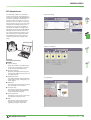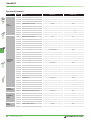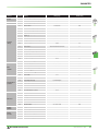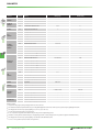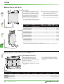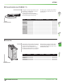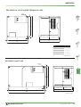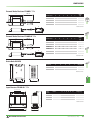
1
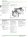
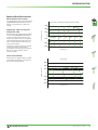
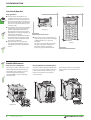
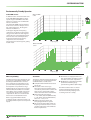
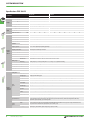
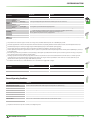
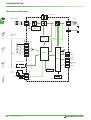
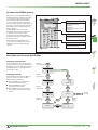
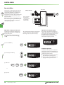
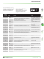
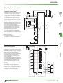
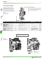
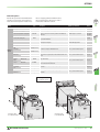
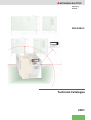
MITSUBISHI ELECTRIC
Frequency
Inverter
FR-E 500 EC
Technical Catalogue
2001
FR-E 500 EC: The next Generation of Frequency Inverters
ct
The Compa
r
All-Rounde
With the next generation of frequency inverters MITSUBISHI
ELECTRIC offers high-tech equipment at particular compact
dimensions. The frequency inverters of the FR-E 500 EC series are the
right frequency inverters for low to medium capacity drive tasks.
The inverters are available for a performance range of 0.4 to 2.2 k
(1 phase) and 0.4 to 7.5 k (3 phase).
Further Publications within the Factory Automation Range
Technical catalogues FR-A 500 and FR-S 500
Technical
Catalogues
Product catalogue for frequency inverters and accessories
of the FR-A 540 (L) EC and FR-S 500 series
Technical catalogues MELSERVO and Motion Controllers
Product catalogues for MR-J2 series amplifiers, servo motors
and motion controllers with SSCNET connection
Technical catalogues PLC and HMI
Product catalogues for programmable logic controllers,
operator terminals, software, and accessories of the
MELSEC PLC series
Networks Technical Catalogue
Product catalogue for Master and Slave modules as well as accessories for the use of programmable logic controllers and frequency
inverters in open and MELSEC networks (art. no. 136730)
Additional services
You will find current information on updates, alterations, new items, and technical support on MITSUBISHI ELECTRIC's web pages
(www.mitsubishi-automation.com) or in the MITSUBISHI faxback system MEL-FAX (Fax: +49 2102 / 486-485 or -790).
The products section of the MITSUBISHI home site includes various documentations of the whole product range by MITSUBISHI
ELECTRIC as well as the current version of this catalogue on hand. All manuals and catalogues can be downloaded.
The content is updated daily and to date is provided in German and English.
About this product catalogue
This catalogue is periodically updated due to product range enlargement, technical changes or new or changed features.
Texts, figures and diagrams shown in this product catalogue are intended exclusively for explanation and assistance in planning and ordering
the frequency inverter series FR-E 500 EC/ECR and the associated accessories. Only the manuals supplied with the devices are relevant for
installation, commissioning and handling of the devices and the accessories. The information given in these manuals must be read before
installation and commissioning of the devices or software.
Should questions arise with regard to the planning of devices described in this product catalogue, do not hesitate to contact MITSUBISHI
ELECTRIC EUROPE B.V. in Ratingen (Germany) or one of its distributors (see cover page).
© MITSUBISHI ELECTRIC EUROPE B.V. 07/2001 (2. edition - version B)
2
FR-E 500 EC
MITSUBISHI ELECTRIC
CONTENTS
FREQUENCY INVERTER FR-E 500 EC
SYSTEM DESCRIPTION
웇
웇
웇
웇
웇
Introduction of the FR-E series . . . . . . . . . . . . . . . . . . . . . . . . . . . . . . . . . . . . . . . . . . . . . . . . . . . . . . . . . . . . . . . . . . . . . . . . . . . . . 4
Speed/torque characteristics . . . . . . . . . . . . . . . . . . . . . . . . . . . . . . . . . . . . . . . . . . . . . . . . . . . . . . . . . . . . . . . . . . . . . . . . . . . . . . 5
Equipment and configuration . . . . . . . . . . . . . . . . . . . . . . . . . . . . . . . . . . . . . . . . . . . . . . . . . . . . . . . . . . . . . . . . . . . 6
Specifications . . . . . . . . . . . . . . . . . . . . . . . . . . . . . . . . . . . . . . . . . . . . . . . . . . . . . . . . . . . . . . . . . . . . . . . . . . . . . . . . . . . . . . . . . . . . . 8
Terminal assignment. . . . . . . . . . . . . . . . . . . . . . . . . . . . . . . . . . . . . . . . . . . . . . . . . . . . . . . . . . . . . . . . . . . . . . . . . . . . . . . . . . . . . 10
CONTROL PANELS
웇
웇
웇
웇
Control panel (parameter unit) FR-PA02-02 . . . . . . . . . . . . . . . . . . . . . . . . . . . . . . . . . . . . . . . . . . . . . . . . . . . . . . . . . . . . . . . 12
Control panel (parameter unit) FR-PU04 . . . . . . . . . . . . . . . . . . . . . . . . . . . . . . . . . . . . . . . . . . . . . . . . . . . . . . . . . . . . . . . . . . 13
Operating modes . . . . . . . . . . . . . . . . . . . . . . . . . . . . . . . . . . . . . . . . . . . . . . . . . . . . . . . . . . . . . . . . . . . . . . . . . . . . . . . . . . . . . . . . 14
Setup software . . . . . . . . . . . . . . . . . . . . . . . . . . . . . . . . . . . . . . . . . . . . . . . . . . . . . . . . . . . . . . . . . . . . . . . . . . . . . . . . . . . . . . . . . . 15
PARAMETERS
웇 Overview of parameters. . . . . . . . . . . . . . . . . . . . . . . . . . . . . . . . . . . . . . . . . . . . . . . . . . . . . . . . . . . . . . . . . . . . . . . . . . . . . . . . . . 16
PROTECTIVE FUNCTIONS
웇 Overview of protective functions . . . . . . . . . . . . . . . . . . . . . . . . . . . . . . . . . . . . . . . . . . . . . . . . . . . . . . . . . . . . . . . . . . . . . . . . . 19
웇 Resetting methods. . . . . . . . . . . . . . . . . . . . . . . . . . . . . . . . . . . . . . . . . . . . . . . . . . . . . . . . . . . . . . . . . . . . . . . . . . . . . . . . . . . . . . . 20
APPLICATIONS
웇 Sample applications . . . . . . . . . . . . . . . . . . . . . . . . . . . . . . . . . . . . . . . . . . . . . . . . . . . . . . . . . . . . . . . . . . . . . . . . . . . . . . . . . . . . . 21
ACCESSORIES
웇
웇
웇
웇
웇
Internal and external options . . . . . . . . . . . . . . . . . . . . . . . . . . . . . . . . . . . . . . . . . . . . . . . . . . . . . . . . . . . . . . . . . . . . . . . . . . . . . 22
Noise filters . . . . . . . . . . . . . . . . . . . . . . . . . . . . . . . . . . . . . . . . . . . . . . . . . . . . . . . . . . . . . . . . . . . . . . . . . . . . . . . . . . . . . . . . . . . . . . 24
Input reactors. . . . . . . . . . . . . . . . . . . . . . . . . . . . . . . . . . . . . . . . . . . . . . . . . . . . . . . . . . . . . . . . . . . . . . . . . . . . . . . . . . . . . . . . . . . . 24
Brake resistors . . . . . . . . . . . . . . . . . . . . . . . . . . . . . . . . . . . . . . . . . . . . . . . . . . . . . . . . . . . . . . . . . . . . . . . . . . . . . . . . . . . . . . . . . . . 25
Brake units . . . . . . . . . . . . . . . . . . . . . . . . . . . . . . . . . . . . . . . . . . . . . . . . . . . . . . . . . . . . . . . . . . . . . . . . . . . . . . . . . . . . . . . . . . . . . . 25
DIMENSIONS
웇
웇
웇
웇
웇
웇
Parameter units. . . . . . . . . . . . . . . . . . . . . . . . . . . . . . . . . . . . . . . . . . . . . . . . . . . . . . . . . . . . . . . . . . . . . . . . . . . . . . . . . . . . . . . . . . 26
Frequency inverters. . . . . . . . . . . . . . . . . . . . . . . . . . . . . . . . . . . . . . . . . . . . . . . . . . . . . . . . . . . . . . . . . . . . . . . . . . . . . . . . . . . . . . 27
Filters . . . . . . . . . . . . . . . . . . . . . . . . . . . . . . . . . . . . . . . . . . . . . . . . . . . . . . . . . . . . . . . . . . . . . . . . . . . . . . . . . . . . . . . . . . . . . . . . . . . 28
Brake resistors . . . . . . . . . . . . . . . . . . . . . . . . . . . . . . . . . . . . . . . . . . . . . . . . . . . . . . . . . . . . . . . . . . . . . . . . . . . . . . . . . . . . . . . . . . . 29
Brake units . . . . . . . . . . . . . . . . . . . . . . . . . . . . . . . . . . . . . . . . . . . . . . . . . . . . . . . . . . . . . . . . . . . . . . . . . . . . . . . . . . . . . . . . . . . . . . 29
Input reactors. . . . . . . . . . . . . . . . . . . . . . . . . . . . . . . . . . . . . . . . . . . . . . . . . . . . . . . . . . . . . . . . . . . . . . . . . . . . . . . . . . . . . . . . . . . . 29
APPENDIX
웇 Order form . . . . . . . . . . . . . . . . . . . . . . . . . . . . . . . . . . . . . . . . . . . . . . . . . . . . . . . . . . . . . . . . . . . . . . . . . . . . . . . . . . . . . . . . . . . . . . 30
웇 Index . . . . . . . . . . . . . . . . . . . . . . . . . . . . . . . . . . . . . . . . . . . . . . . . . . . . . . . . . . . . . . . . . . . . . . . . . . . . . . . . . . . . . . . . . . . . . . . . . . . . 31
MITSUBISHI ELECTRIC
FR-E 500 EC
3
SYSTEM DESCRIPTION
The Frequency Inverter FR-E 500 EC
Due to its versatility and compact dimensions the FR-E 500 EC - newly developed
by MITSUBISHI ELECTRIC - is a frequency
inverter solving most effectively your
individual drive tasks.
Its extensive functions allow flexible applications. The outstanding drive features of
the FR-E 500 EC suits various needs:
The inverters are available for a performance range of 0.4 to 2.2 kW (1 phase) and of
0.4 to 7.5 kW (3 phase).
The output frequency ranges from 0.2 to
400 Hz.
앬 Textile machines such as spinning
앬
앬
앬
앬
앬
machines, knitting machines, weaving
looms
Material transport systems such as
chain, belt, and screw conveyors
Door and gate drives
Machines for working of metal, stone,
wood, and plastics
Palettisers, material-handling
technology
Pumps and ventilating
POWER
ALARM
MITSUBISHI
Hz RUN
A MON
PU EXT
RUN
STOP
RESET
MITSUBISHI
Full Product Line-Up
Communications capability as a
standard function
Comprehensive protection
functions for safe operation
Operating functions and other
convenient functions
An RS485 interface for data communications is standard equipment of the
FR-E 500. The interface can be accessed
after removing the parameter unit and
serves for data exchange for example with
a personal computer.
앬 Instantaneous power failure stop
앬 Frequency jumps (three points) to avoid
Compatible with many new
applications
앬 PID control
The integrated PID control facilitates for
example flow control using pumps.
앬 Stop selection
Select either decelerating stop or
coasting stop, depending on machine
specification.
restart function. By this function
the motor can start while coasting.
앬 Built-in electronic overcurrent
protection
앬 Free selection of the protection
function for automatic retry after
alarm occurence.
Compatible with numerous I/Os
앬
앬
앬
FR-E 500 EC
ing actual operating time and much
more
앬 Switch between two sets of motor
characteristics by means of a second
parameter function
앬 Zero current detection
앬 Multi-speed operation
앬
4
the machine's resonant frequency
앬 Fast acceleration/deceleration mode
앬 Full monitoring capabilities for monitor-
(15 different pre-selected speeds are
available)
4 to 20 mA control input
Multi-input terminals:
select four inputs from 11 possible
input types
Multi-output terminals:
select three outputs from 12 possible
output types
24 V external power supply output
(permissible values: 24 V DC/0.1 A)
MITSUBISHI ELECTRIC
SYSTEM DESCRIPTION
Optimised Drive Characteristics
Advanced flux vector control
The original flux vector control developed
by MITSUBISHI ELECTRIC offers new performance characteristics in drive technology.
By combining slip compensation and flux
vector control MITSUBISHI ELECTRIC has
achieved a loaded torque of 150 % at a
frequency of 1 Hz. Due to the integrated
auto-tuning function the flux vector control is even provided for widely varying
motor characteristics.
The figures compare rational speed/load
torque characteristics and rational
speed/motor current for general purpose
flux vector control and V/F control
(motor 0.75 kW).
300
200
Loaded torque (%)
High torque (150 %) at very low
frequencies (1 Hz)
Flux vector control (slip compensation selected)
100
0
30 90180 300
600
900
1200
1500
1800
-100
-200
-300
-1
Speed (min. )
Inrush current limiter
All inverters are equipped with an inrush
current limiter providing a protection of
the connected components.
V/f control
300
Loaded torque (%)
200
100
0
90
300
900
1500
1800
-100
-200
-300
-1
Speed (min. )
MITSUBISHI ELECTRIC
FR-E 500 EC
5
SYSTEM DESCRIPTION
User-friendly Operation
Easy operation
앬 The parameter unit FR-PA02-02 is
available for all frequency inverters. It
provides a clear and easy operation of
the inverter and displays several operational and alarm signals. The parameter
unit can be connected remotely via an
extension cable.
앬 The FR-PU04 control panel is optionally
available. It provides a long-life backlight LC display. Operational data is
directly input via the numeric keypad.
Eight different selectable languages are
supported on the display.
The integrated copy function transfers
the entire parameter settings to other
inverters and thus shortens the initialisation time significantly.
앬 All parameters can be assigned to
user groups thus supplying only the
required parameters for specific applications.
PARAMETER UNIT
FR-PU-04
FR-PA02-02
Hz
50 0 0 Hz
PU
- - - STOP EXT
RUN
STOP
RESET
FR-PA02-02
앬 The inverter can be controlled alterna-
tively via the parameter unit or through
an RS485 interface via a personal
computer.
For setting, parameterizing, and monitoring via a personal computer the
VFD Setup Software is required
(refer to page 15 for further details).
MON
SET
EXT
HELP
SHIFT
ESC
7
8
9
4
5
6
1
2
3
PU
FWD
REV
STOP
0
WRITE
RESET
READ
FR-PU04
Simplified Maintenance
Easy access to cooling fans
Easy installation and maintenance
The easily accessible cooling fans can be
replaced quickly and easily if required.
The lifetime of the cooling fans can be
extended significantly through a
selective ON/OFF control specified by
parameter 244.
Since the control and power terminal block
is easy of access, the installation and maintenance of the inverter is also very easy.
All connection points are designed as
screw terminals.
The housing includes a cable routing
facility which can be removed for installing.
POWER
A
RH
ALARM
RM
B
RL
C
AM
4
PC
SD
SE
STF
RUN
STR
FU
SD
SINK
SOURCE
-
P1
+
AM
4
SE
PC
SD
SINK
SE
RUN
5
SD
PR
2
5
PC
2
RES
PC
SE
C
10
SD
10
SD
RL
RES
SD
A
RH
MRS
B
RM
MRS
FU
SOURCE
-
P1
+
STF
STR
SD
PR
FAN
2
FAN
1
FAN
2
FAN
1
FR-E 520S EC
6
FR-E 500 EC
MITSUBISHI ELECTRIC
SYSTEM DESCRIPTION
Environmentally Friendly Operation
Time [s]
Frequency [Hz]
Without Soft-PWM
control
Noise level
In addition to the conventional low-noise
mode, MITSUBISHI ELECTRIC has developed its original Soft-PWM control that
suppresses acoustic noise and limits RFI
noise to a minimum.
The switchable PWM control facilitates a
motor noise as silent as whisper even at
low carrier frequencies. The diagrams
illustrate the difference.
In the upper diagram the frequency
components are dispersed: The inverter
only generates little noise that might be
compared to the sound of flowing water.
The noise does not sound unpleasant.
In the lower diagram the frequency
components are concentrated:
The inverter generates the typical grating
metallic noise.
With Soft-PWM
control
Noise level
Soft-PWM control
Time [s]
Frequency [Hz]
EMC compatibility
Standards
The FR-E 500 EC inverter regarding its electromagnetic compatibility complies with
the European EMC directives. To meet
these standards specially adjusted compact noise filters (“foot print”) have been
developed for each performace range.
Additionally, for the single-phase inverter
FR-E 520S EC built-on filters are available.
These filters can be installed easily on the
rear side of the inverter into a prepared
compartment. There is no need for additional room or extended dimensions.
Refer to page 24 for further details.
To limit the inrush current the inverter can
be equipped with a input reactor upon the
inputs.
The devices of the FR-E 500 EC product line
are designed to be used world-wide without further effort or certifications.
앬 Compliant with world-wide standards
CE, UL, cUL
앬 Selectable sink or source logic
The logic for input and output signals
can be freely selected. The result is a flexible and easy customisation of the
units to the needs of the world market.
앬 Extended rated input voltage
1~ 200–240 V; 50/60 Hz (FR-E 520S EC)
3~ 380–480 V; 50/60 Hz (FR-E 540 EC)
Tolerance: −15 %; +10 %
앬 Multi-language parameter unit
(8 languages) available as option
앬 Due to the integrated PID control the
frequency inverter for instance can be
used for temperature control without
further requirements.
MITSUBISHI ELECTRIC
앬 All inverters are equipped with an in-
rush current limiter providing a protection of the connected components.
앬 MS-Windows compatible world-wide
standardised multi-language
parameterising software (VFD-Setup)
The FR-E 500 EC therefore is a world
product complying with all relevant
standards and easily adopting to the
according needs of a country.
FR-E 500 EC
7
SYSTEM DESCRIPTION
Specifications FR-E 500 EC
FR-E 520S EC
Product line
0.4 k
Rated motor capacity
�
Rated motor capacity
Input
2.2 k
0.4 k
0.75 k
1.5 k
2.2 k
3.7k
5.5 k
7.5 k
kW 0.4
0.75
1.5
2.2
0.4
0.75
1.5
2.2
3.7
5.5
7.5
1.5
2.7
3.8
1.2
2.0
3.0
4.6
7.2
9.1
13.0
A 2.5
4
7
10
1.6 (1.4)
2.6 (2.2)
4 (3.8)
6 (5.4)
9.5 (8.7)
12
17
9
12
17
Overload capacity �
200 % of rated motor capacity for 0.5 s; 150 % for 1 min.
Voltage �
3-phase, 0 V up to power supply voltage
Power supply voltage
1-phase, 200–240 V AC, −15 % / +10 %
Voltage range
170–264 V AC at 50 / 60 Hz
323–528 V AC at 50 / 60 Hz
Frequency range
50 / 60 Hz ± 5 %
50 / 60 Hz ± 5 %
Rated input capacity �
kVA 1.5
2.3
4.0
5.2
3-phase, 380–480 V AC, −15 % / +10 %
1.5
2.5
Control method
Extended flux vector control with online auto tuning of motor data or V/f control
Modulation control
Sine evaluated PWM, Soft PW
Carrier frequency
0.7–14.5 kHz (user adjustable)
Frequency range
0.2–400 Hz
Frequency
resolution
Control
specifications
1.5 k
kVA 0.95
Rated current �
Output
FR-E 540 EC
0.75k
4.5
Analog
From terminals 2-5: 1/500 of maximum set frequency (input 5 V DC); 1/1000 (input 10 V, 20 mA DC)
Digital
0.01 Hz / 50 Hz (incl. pulse input)
Frequency precision
±0.5 % of max. output frequency (temperature range 25 °C±10 °C) during analog input;
±0.01 % of max. output frequency during digital input
Voltage /
frequency characteristics
Base frequency adjustable from 0 to 400 Hz;
constant torque or variable torque selectable
Possible starting torque
≥ 150 % / 1 Hz, ≥ 200 % / 3Hz (for vector control oder slip compensation)
Torque boost
Manual torque boost; selectable between 0–30 %
Acceleration / deceleration time
0.01; 0.1 to 3600 s individual settings
Acceleration / deceleration characteristics
Regenerative
Braking torque
�
DC braking
Linear or S-form course, user selectable
0.4 k and 0.75 k: 100 % or more; 1.5 k: 50 % or more; 2.2 k to 7,5 k: 20 % or more
Braking time and braking moment adjustable,
Operating frequency: 0–120 Hz, operating time: 0–10 s, voltage: 0–30 % (adjustable externally)
Current stall prevention operation level
Operation current level setting possible (0–200 % variable), enable/disable selection
Voltage stall prevention operation level
Operation level is fixed, enable/disable selection
High-response current restriction level
Operation level is fixed, enable/disable selection
Motor protection
Frequency
setting values
5.5
Electronic motor protection relay (rated current user adjustable)
Analog input
0–5 V DC, 0–10 V DC, 4–20 mA
Digital input
From control panel (parameter unit), RS-485 or network
Starting signal
Individual selection of forward / reverse run
Starting signal self retaining input
Multi-speed selection Up to 15 set speeds (each speed can be set between 0 and 400 Hz; speed can be changed via control panel or during operation)
Input
signals
Control
signals for
operation
2nd function
Selects 2nd function (acceleration time, deceleration time, torque boost, base frequency, electronic overcurrent protection)
Selection of
current input
Frequency setting via current input signal 4 to 20 mA DC
External
thermal input
Stopping the inverter with an externally mounted thermal relay
PU<->external
operation
Switch over between the operating modes "PU" and "External"
V/F<->flux vector
control
External switching between V/F control and general-purpose flux vector control
Output stop
Instant cutoff of inverter output (frequency and voltage)
Error reset
The error indication (alarm signal) is reset with the reset of the protective function
Maximum and minimum frequency setting, frequency jump operation, external thermal input selection, instantaneous power failure restart
operation, forward run/reverse run prevention, slip compensation, operation mode selection, off-line auto tuning function, PID control,
computer link operation (RS485), open network operation
Operation functions
Output
signals
8
Operation
status
2 output types (open collector output) can be selected: inverter running, frequency reached, frequency detection, overload warning, zero return
detection, output current detection, maximum PID, minimum PID, PID forward run, PID reverse run, operation ready, minor failure and error.
1 relay contact can be selected for the output (230 V AC; 0.3 A / 30 V DC; 0.3 A)
Analog signal
One of the following output types can be selected:
output frequency, motor current, output voltage, analog output (0–10 V DC).
FR-E 500 EC
MITSUBISHI ELECTRIC
SYSTEM DESCRIPTION
FR-E 520S EC
Product line
Display
option
Protection
Others
0.4 k
0.75k
FR-E 540 EC
1.5 k
2.2 k
0.4 k
0.75 k
1.5 k
2.2 k
Displayed on
control panel
(FR-PU04/
FR-PA02-02)
Operating state
Outputfrequency,motorcurrent,outputvoltage,frequencysettingvalue,operationspeed
Alarm display
Error messages are displayed after a protective function is activated. Up to 4 error codes can be stored.
Additional
displays on
control panel
FR-PU04
Operating state
Signal status of input and output terminals
Interactive
operating guide
Interactive guide for operation and troubleshooting via help function
3.7k
5.5 k
7.5 k
Overcurrent cutoff (during acceleration, deceleration, constant speed), regenerative overvoltage cutoff, undervoltage � , instantaneous power failure �, overload cutoff (electronic thermal relay), brake transistor error, ground fault overcurrent, output short circuit,
stall prevention, overload warning, brake transistor overheating, fin overheating, fan error � ,
option error, parameter error, PU connection error, output phase error
Functions
Protection rating
IP 20
Cooling
Self-cooling
Weight (kg)
1.9
Fan cooling
1.9
2.0
Self-cooling
2.0
1.9
1.9
2.0
2.1
Fan cooling
2.1
3.8
3.8
�
The specifications of the rated motor capacity are related to a motor voltage of 400 V, a maximum ambient temperature of 40 °C and PWM frequency of 1 kHz.
�
The overload capacity indicated in % is the ratio of the overload current to the inverters rated current. For repeated duty, allow time for the inverter and motor to return to or below the temperature and 100 % load.
�
The maximum output voltage cannot exceed the power supply voltage. The maximum output voltage may be set as desired below the power supply voltage.
�
The power supply capacity changes with the values of the power supply side inverter impedances (including those of the input reactor and cables).
�
The rated output current in the parentheses applies when low acoustic noise operation is to be performed at an ambient temperature higher than 40 °C with the parameter 72 (PWM frequency selection) value set to 2 kHz or higher.
�
When undervoltage or instantaneous power failure has occurred, alarm display or alarm output is not provided but the inverter itself is protected. Overcurrent, regenerative overvoltage, or other protection
may be activated at power restoration according to the operating condition.
�
The braking torque indicated is short-duration average torque (which varies with motor loss) when the motor alone is decelerated from 50 Hz in the shortest time and is not a continuous regenerative
torque. When the motor is decelerated from the frequency higher than the base frequency, the average deceleration torque will reduce. Since the inverter does not contain a brake resistor, use the
optional brake resistor when regenerative energy is large. A brake unit BU may also be used.
�
Not valid for the inverters FR-E 540-0.4 k, -0.75 k EC and FR-E 520S-0.1 k to -0.4 k EC which are not equipped with a cooling fan.
FR-E 520S EC
Product line
Order information
Art. no.
FR-E 540 EC
0.4 k
0.75k
1.5 k
2.2 k
0.4 k
0.75 k
1.5 k
2.2 k
3.7 k
5.5 k
7.5 k
102938
102939
102940
102941
69197
69198
69200
69201
69204
102942
102943
General Operating Conditions
Item
Specifications
Ambient temperature in operation
-10 °C to +50 °C (non-freezing)
For selection of the load characteristics with variable torque the max. temperature is 40 °C (FR-E 540 only).
Storage temperature �
-20 to +65 °C
Ambient humidity
Max. 90 % RH (non-condensing)
Altitude
Max. 1000 m above sea level; After that derate by 3 % for every extra 500 m up to 2500 m (91 %).
Protection rating
IP 20
Shock resistance
10 G (3 times each in 3 directions)
Vibration resistance
0.6 G: resistance to vibrations from 10 to 55 Hz for 2 hours along all 3 axes
Ambient conditions
For indoor use only, avoid environments containing corrosive gases, install in a dust-free location.
Certifications
UL / CSA / CE / EN
�
Temperature to which units can be exposed for a short time, such as during transportation.
MITSUBISHI ELECTRIC
FR-E 500 EC
9
SYSTEM DESCRIPTION
P1
+
PR
Block Diagram (Source Logic)
Converter
Motor
Power supply*
L1
L2
L3
U
V
W
Voltage
supply
Input signal
circuits
Protective
functions
PC
STF
STR
RH
RM
RL
MRS
RES
SD
Reset
ALARM
CPU
LSI
A
B
C
Error
output
AM
5
Analog
output
SE
RUN
FU
Operating
state
output
Parameter unit
PU/PA
Options
0–5 V
0–10 V
1kΩ/2W
0–20 mA
10
FR-E 500 EC
10
2
5
4
LED/LC display PU/PA
MITSUBISHI ELECTRIC
SYSTEM DESCRIPTION
Terminal Assignment of Signal Terminals
Function
Control
connection
Common
Setting value
specification
Signal
outputs
Interface
Terminal
Description
STF
Forward rotation start
The motor rotates forward, if a signal is applied to terminal STF.
STR
Reverse rotation start
The motor rotates reverse, if a signal is applied to terminal STR.
RH, RM, RL
Multi-speed selection
Preset of 15 different output frequencies
MRS
Output stop
The signal stops the output frequency without regard to the delay time. This terminal is used to bring the motor to a stop by the electromagnetic brake.
RES
RESET input
An activated protective circuit is reset, if a signal is applied to the terminal RES (t > 0,1 s).
SD
A determined control function is activated, if the corresponding terminal is connected to the terminal SD. The SD terminal is
Common sink for contact input/
isolated from the digital circuits via optocouplers.
reference potential
Common reference potential (sink logic) for 24 V DC/0.1 A output (PC terminal).
PC
+24 V DC output
24 V DC/0.1 A output; reference potential for source logic
10
Voltage output for
potentiometer
Output voltage 5 V DC
Max. output current 10 mA
Recommended potentiometer: 1 kΩ, linear
2
Input for frequency setting
value signal
The voltage setting value 0–5 (10) V is applied to this terminal. The voltage range is preset to 0–5 V.
The input resistance is 10 kΩ.
5
Reference point for frequency
setting value signal
Terminal 5 is the reference point for all analog setting values and for the analog output signal AM. The terminal is not isolated from
the reference potential of the control circuit and must not be earthed.
4
Input for current
setting value signal
4–20 mA DC
The current setting value signal (4–20 mA DC) is applied to this terminal. The input resistance is 250 Ω.
A, B, C
Potential free
alarm output
The alarm is output via relay contacts. The block diagram shows the normal operation and voltage free status. If the protective function is activated, the relay picks up.The maximum contact load is 230 V AC / 0,3 A or 30 V DC / 0,3 A.
RUN
Signal output for
motor operation
The output is switched low, if the inverter output frequency is equal to or higher than the starting frequency.
The output is switched high, if no frequency is output or the DC brake is in operation.
FU
Signal output for
monitoring output frequency
The output is switched low once the output frequency exceeds a value preset in parameter 42 (or 43). Otherwise the FU output is
switched high.
SE
Reference potential for
signal outputs
Reference potential for the signals RUN and FU. This terminal is isolated from the reference potential of the control
circuit PC/SD.
AM
Analog output
One of 3 monitoring functions can be selected, e.g. external frequency output.
The functions are determined by parameters.
A DC voltmeter can be connected. The max. output voltage is 10 V.
—
Connection of
control panel (RS485)
Communications via RS485
I/O standard: RS485, Multi-Drop operation, max. 19200 Baud
Terminal Assignment of Main Circuit Terminals
Function
Main circuit
connection
Terminal
Terminal name
Description
L1, L2, L3*
Power supply connection
Power supply of the inverter (380–480 V AC, 50/60 Hz)
+, −
External brake unit connection
An external brake unit can be connected to the terminals + and − .
+, PR
Optional external brake resistor
connection
An optional external brake resistor can be connected to the terminals + and PR.
Disconnect the jumper from terminals PR and PX before (for FR-E 540-0.4 k to 7.5 k only).
P1, +
Converter choke coil connection
An optional choke coil can be connected to the terminals P1 and +.
Disconnect the jumper from terminals P1 and + before.
U, V, W
Motor connection
Voltage output of the inverter (3-phase, 0 V up to power supply voltage, 0.2–400 Hz)
PE
Protective earth connection of inverter
* L1, N for 1-phase connection
MITSUBISHI ELECTRIC
FR-E 500 EC
11
CONTROL PANELS
Parameter Unit FR-PA02-02 (optional)
The parameter unit FR-PA02-02 is the standard control device for the frequency inverter FR-E 500 EC. It fulfils the major tasks
for operating the inverter achieving
a particular cost effectiveness.
The parameter unit supports the input and
display of several control variables
(parameters) and monitores and indicates
current operational data. The data is displayed on a 4-digit LED display.
Besides displaying and setting parameters
all operating states of the inverter and
motor can be monitored. Faults are indicated by error codes.
The parameter unit can alternatively be
attached directly on the inverter or via
cable connection mounted remotely,
e.g. in a control cabinet.
LED display
FR-PA02-02
4-digit 7-segment display for indication of
operational data, error codes, and several
functions
Hz RUN
A MON
PU EXT
REV
SET
MODE
STOP
RESET
FWD
Indication of unit and operating state
LED for indication of current unit:
앫 frequency (Hz)
앫 current (A)
Indication of operating state:
앫 under operation (RUN)
앫 monitor mode (MON)
앫 operation via parameter unit (PU)
앫 external operation (EXT)
Hz RUN
A MON
PU EXT
RUN
Function keys (behind the cover)
STOP
RESET
Keys for set-up, menu functions, and
inverter start and stop
Menu Guide to the Parameter Unit FR-PA02-02
Frequency display
Monitor
menu
FR-PA02-02
Current display
SET
FR-PA02-02
Voltage display
SET
FR-PA02-02
Alarm display
SET
FR-PA02-02
Hz
MON
EXT
A
SET
MON
EXT
MON
PU EXT
MON
EXT
SET
SET
SET
SET
MODE
MODE
Frequency setting
FR-PA02-02
Frequency
setting
menu
FR-PA02-02
SET
Hz
Hz
PU
PU
FR-PA02-02
Hz
MON
EXT
MODE
Parameter number
Parameter
setting
menu
FR-PA02-02
FR-PA02-02
Parameter value
SET
FR-PA02-02
PU
PU
PU
Save value
SET
FR-PA02-02
PU
ca. 1,5 s
SET
MODE
Operation via
control panel
Operation
menu
JOG operation
FR-PA02-02
FR-PA02-02
External operation
FR-PA02-02
PU
PU
MODE
EXT
MODE
Help
menu
MODE
Alarm
history
FR-PA02-02
Memory
clear
Parameter
clear
All
clear
Software
version
PU
12
FR-E 500 EC
MITSUBISHI ELECTRIC
CONTROL PANELS
Parameter Unit FR-PU04 (optional)
The parameter unit FR-PU04 including extended functions is available as optional
accessory. It provides a 10-key keypad
for entering directly numerical values.
A 4-row LC display returns operational
data, parameter names or status and error
messages in uncoded text. The parameter
unit displays text in the following selectable languages:
English, German, French, Spanish,
Swedish, Italian, Finnish, and Japanese.
In addition to the functions of the
standard parameter unit the FR-PU04
displays and monitors 21 different values
and states in total.
The parameter unit FR-PU04 is used
instead of the standard parameter unit
FR-DU04 and can be replaced by this
after use.
PARAMETER UNIT
FR-PU-04
4-row Liquid Cristal Display (backlit)
앫 Interactive parameter setting
앫 Help function
앫 Error indication
앫 21 different displays (frequency, current,
voltage, etc.)
50 0 0EXHzT
- - - STOP
MON
SET
EXT
HELP
SHIFT
ESC
7
8
9
4
5
6
1
2
3
WRITE
0
READ
Display of
output frequency
MONITOR
LC display
PU
Buttons for selecting operating mode
The desired operating mode is selected by
pressing the buttons MONITOR, SET, EXT OP or
PU OP.
FWD
REV
Function keys and numerical keys
STOP
Keys for selecting specific functions via display
and entering of numerical values
RESET
Menu Guide to the Parameter Unit FR-PU04
Displaying parameter lists
Press the SET key to enter the parameter
setting menu. Then press the HELP key to
display the parameter lists. After pressing
the READ key, the according parameter
value will be read in.
0 0 0 Hz
- - - STOP EXT
Copying parameters
Press the SET key and then the ▲ key to
enter the copy mode. There are the
following three possibilities:
앬 Press the READ key to read out all
parameters from the inverter.
앬 Press the WRITE key to write
parameters to the inverter.
앬 Press the ▼ key to verify the values
stored in the parameter unit and the
inverter.
Display of
output current
SHIFT
SHIFT
0.00Hz
0.00A
0. 0V
- - - STOP EXT
0 00
A
- - - STOP EXT
Display of
output voltage
SHIFT
SHIFT
Others
0 00V
<HELP>
- - - STOP EXT
Display of
alarm history
SHIFT
SHIFT
Al ar m Hi stor y
<READ>
MITSUBISHI ELECTRIC
READ
SHIFT
HELP
Monitor
selection
Display of
alarms
(up to 8)
1 UVT 5
2 UVT 6
7
3
8
4
FR-E 500 EC
13
CONTROL PANELS
Operating Modes
The inverter can alternatively be operated
via external signals or directly via the parameter units FR-PA02-02 or FR-DU04. A
combined operation is possible too.
The operating mode on the parameter unit
FR-PA02-02 is selected within the operation mode menu.
With the parameter unit FR-PU04 the selection is done by pressing the EXT OP key for
external signal operation and PU OP for
control panel operation.
FR-E 540 EC
Sample connection
Q1
L1
I
L1
L2
I
L2
V
L3
I
L3
W
These connections
are required for
combined operation
or operation by
external signals.
U
PC
S1
S2
STR
STF
10
2
R1
5
PE
Operation via external signals
Operation via the parameter unit
The direction of rotation and frequency
setting of the inverter are controlled via
the parameter unit.
The setting of the output frequency is
increased or decreased via the keys ▲
and ▼.
The example below shows the operational
steps for a frequency setting including
following motor start and motor stop.
The direction of rotation and frequency
setting of the inverter are controlled by external signals. The following figure shows
the display on the parameter unit
FR-PA02-02 for forward rotation of the
motor and a frequency of 50 Hz.
FR-PA02-02
햲 Press the MODE key
Hz RUN
MON
EXT
FR-PA02-02
Hz
MODE
PU
Combined operation
햳 Set frequency with SET key
In addition to the operation via external
signals and via parameter unit (FR-PA02-02 /
FR-PU04) the inverter can be operated in
combined operation mode.
앬 Setting value preset via the parameter
unit and external starting signal
앬 External setting value signal and starting signal via the parameter unit
FR-PA02-02
Hz
PU
햴 Start motor
FR-PA02-02
RUN
FWD
Hz RUN
REV
PU
or
햵 Stop motor
FR-PA02-02
STOP
RESET
Hz
MON
PU
14
FR-E 500 EC
MITSUBISHI ELECTRIC
CONTROL PANELS
VFD Setup Software
The VFD Setup Software is a powerful
tool for the operation of your frequency
inverter. The software is MS Windows 3.11
and 95/98 compatible, and therefore allows the inverter operation via any conventional personal computer. Several frequency inverters can be set up, operated,
and monitored simultaneously across a
network or via a personal computer or
notebook. The software is designed for
all frequency inverters of the MITSUBISHI
FR-A 500, FR-E 500 and FR-S 500 series.
The connection between personal computer and inverter is established either
via an RS485 network or directly via an
SC-FR PC adapter cable available separately.
MITSUBISHI
Parameter setting
Display and monitor
Benefits
앬 System settings
앬
앬
앬
앬
앬
앬
Due to the network capabilities of the
inverter up to 32 frequency inverters
can be operated simultaneously.
Parameter settings
By means of overall and function related overviews different parameters can
be adjusted easily.
Display functions
The comprehensible display functions
enable data, analog, oscillograph, and
alarm displays.
Diagnostis
The analysis of the inverter status provides a thorough error correction.
Test operation
The test operation provides a simulation of the operation and adjustment
via the auto-tuning function.
File management
Parameters can be saved on the personal computer and printed out.
Help
The extensive online help provides
support concerning all questions
regarding settings and operation.
MITSUBISHI ELECTRIC
Test operation
FR-E 500 EC
15
PARAMETER
Overview of Parameters
Parameter
Function
Basic
parameters
Parameters for
standard drive
operation
Settings of
control outputs
2nd parameter
settings
Display
functions
16
Setting range
Default setting
0
Torque boost (manual) �
0–30 %
6%/4%�
1
Maximum output frequency
0–120 Hz
120 Hz
2
Minimum output frequency
0–120 Hz
0 Hz
3
V/f characteristics (base frequency) �
0–400 Hz
50 Hz
4
1. Multispeed (high) preset - RH �
0–400 Hz
60 Hz
5
�
0–400 Hz
30 Hz
Meaning
2. Multispeed (high) preset - RM
�
6
3. Multispeed (high) preset - RL
0–400 Hz
10 Hz
7
Acceleration time
0–360 s / 0–3600 s
5 s / 10 s �
8
Deceleration time
0–360 s / 0–3600 s
5 s / 15 s �
9
Electronic thermal overload relay (motor protection)
0–500 A
Rated current �
10
DC injection brake (initial frequency)
0–120 Hz
3 Hz
11
DC injection brake (operation time)
0–10 s
0,5 s
12
DC injection brake (voltage)
0–30 %
6%
13
Starting frequency
0–60 Hz
0.5 Hz
14
Selection of load pattern �
15
JOG frequency
16
JOG acceleration and deceleration time
18
High-speed max. frequency
19
Max. output voltag e�
20
Acceleration / deceleration reference frequency
21
Acceleration / deceleration time increments
�
0–3
0
0–400 Hz
5 Hz
0–360 s / 0–3600 s
0.5 s
120–400 Hz
120 Hz
0–1000 V/8888/9999
8888
1–400 Hz
50 Hz
0/1
0
0–200 %
150 %
22
Stall prevention operation level
23
Stall prevention operation at double speed �
0–200 % / 9999
9999
24
4. Multispeed preset �
0–400 Hz / 9999
9999
25
5. Multispeed preset �
0–400 Hz / 9999
9999
26
6. Multispeed preset
�
0–400 Hz / 9999
9999
27
7. Multispeed preset �
0–400 Hz / 9999
9999
29
Acceleration / deceleration pattern
0/1/2
0
30
Regenerative function selection
0/1
0
31
Frequency jump 1A
0–400 Hz / 9999
9999
32
Frequency jump 1B
0–400 Hz / 9999
9999
33
Frequency jump 2A
0–400 Hz / 9999
9999
34
Frequency jump 2B
0–400 Hz / 9999
9999
35
Frequency jump 3A
0–400 Hz / 9999
9999
36
Frequency jump 3B
0–400 Hz / 9999
9999
37
Speed display
0 / 0.1–9998
0
38
Frequency at 5 V (10 V) input voltage
1–400 Hz
50 Hz �
39
Frequency at 20 mA input current
1–400 Hz
50 Hz �
41
Setting value / current value comparison (SU output)
0–100 %
10 %
Output frequency monitoring (FU output)
0–400 Hz
6 Hz
42
43
Output frequency detection for reverse rotation
44
2. Acceleration / deceleration
45
2. Deceleration time
46
2. Manual torque boost
�
�
47
2. V/f characteristics (base frequency)
48
2. Electronic overcurrent protection
52
Control panel (PU) main display data selection �
�
55
Frequency monitoring reference
56
External current monitoring reference �
FR-E 500 EC
0–400 Hz / 9999
9999
0–360 s / 0–3600 s
5 s / 10 s �
0–360 s / 0–3600 s / 9999
9999
0–30 % / 9999
9999
0–400 Hz / 9999
9999
0–500 A / 9999
9999
0 / 23 / 100
0
0–400 Hz
50 Hz
0–500 A
Rated current
MITSUBISHI ELECTRIC
PARAMETER
Function
Restart
Aux. function
Operation
settings
Motor
constants
Communications
parameter
Parameter
Auxiliary
functions
Current
detection
Setting range
Default setting
0–5 s / 9999
9999
0–60 s
1s
Restart coasting time after power failure
58
Restart cushion time before automatic synchronisation
59
Selection of digital motor potentiometer
0/1/2
0
60
Shortest acceleration/deceleretion mode
0 / 1 / 2 / 11 / 12
0
61
Reference current
0–500 A / 9999
9999
62
Current limit for intelligent mode (acceleration)
0–200 % / 9999
9999
63
Current limit for intelligent mode (deceleration)
0–200 % / 9999
9999
65
Retry selection
0/1/2/3
0
66
Starting frequency for stall prevention at boost
frequency �
0–400 Hz
50 Hz
67
Number of restart retries
68
Waiting time for automatic restart retry
69
Retry count display erasure
70
Special regenerative brake duty
71
Motor selection �
�
72
PWM function
73
Specification of setting value input data
74
Setting value signal filter
75
Reset condition / connection error / stop
77
78
0–10 / 101–110
0
0.1–360 s
1s
0
0
0–30 %
0%
0/1/3/5/6/13/15/16/
100/101/103/105/106/113/115/116
0
0–15
1
0 / 1 / 10 / 11 �
1
0–8
1
0–3 / 14–17
14
Write protection for parameters
0/1/2
0
Prevention of reverse rotation
0/1/2
0
79
Operation mode selection �
0–4 / 6–8
0
80
Rated motor capacity for flux vector control
0.2–7.5 kW / 9999
9999
82
Motor excitation current
83
84
0–500 A / 9999
9999
Rated voltage of motor for auto-tuning
0–1000 V
200 V / 400 V
Rated motor frequency
50–120 Hz
50 Hz
0–50 Ω / 9999
9999
�
90
Motor constant A
96
Auto-tuning setting/status �
0/1
0
117
Station number
0–31
0
118
Communication speed
48 / 96 / 192
192
119
Stop bit length/data length
0 / 1 Data length 8
10 / 11 Data length 7
1
120
Parity check presence/absence
121
Number of communication retries
122
123
PID control
Meaning
57
0/1/2
2
0–10 / 9999
1
Communication check time interval
0–999.8 s / 9999
9999
Wait time setting
0–150 ms / 9999
9999
124
CR / LF absence/presence selection
128
PID action selection
129
0/1/2
1
0 / 20 / 21
0
PID proportional band
0.1–1000 % / 9999
100 %
130
PID integral time
0.1–3600 s / 9999
1s
131
Upper limit for actual value
0–100 % / 9999
9999
132
Lower limit for actual value
0–100 % / 9999
9999
133
PID action set point for PU operation
0–100 %
0%
9999
134
PID differential time
0.01–10.00 s / 9999
145
Language selection
0–7
146
Parameter set by manufacturer. Do not set.
150
Output current detection level
151
Output current detection period
0–10 s
0
152
Zero current detection level
0–200 %
5%
153
Zero current detection period
0.05–1 s
0.5 s
MITSUBISHI ELECTRIC
1
—
0–200 %
150 %
FR-E 500 EC
17
PARAMETER
Function
Parameter
Sub
functions
156
Stall prevention operation selection
158
AM terminal function selection
160
User group read selection
168
Parameter set by manufacturer. Do not set.
169
1. cushion time for automatic restart
171
Actual operationhour meter clear
173
User group 1 registration
174
User group 1 deletion
175
User group 2 registration
Additional
functions
Initial
monitor
User
functions
Meaning
Setting range
Default setting
0–31/100
0
0/1/2
0
0 / 1 / 10 / 11
0
0/1
0
0–20 s
0s
0
0
0–999
0
0–999 / 9999
0
0–999
0
176
User group 2 deletion
0–999 / 9999
0
180
RL terminal function selection
0–8 / 16 / 18
0
181
RM terminal function selection
0–8 / 16 / 18
1
182
RH terminal function selection
0–8 / 16 / 18
2
183
MRS terminal function selection
0–8 / 16 / 18
6
190
RUN terminal function selection
0–99
0
191
FU terminal function selection
0–99
4
192
ABC terminals function selection
0–99
99
232
Multi-speed setting (speed 8) �
0–400 Hz / 9999
9999
233
Multi-speed setting (speed 9) �
0–400 Hz / 9999
9999
234
Multi-speed setting (speed 10) �
0–400 Hz / 9999
9999
235
Multi-speed setting (speed 11) �
0–400 Hz / 9999
9999
236
Multi-speed setting (speed 12)
�
0–400 Hz / 9999
9999
237
Multi-speed setting (speed 13) �
0–400 Hz / 9999
9999
238
Multi-speed setting (speed 14) �
0–400 Hz / 9999
9999
239
Multi-speed setting (speed 15)
�
0–400 Hz / 9999
9999
240
Soft-PWM setting
0/1
1
244
Cooling fan operation selection
0/1
0
245
Rated motor slip
0–50 % / 9999
9999
246
Slip compensation response time
0.01–10 s
0.5 s
247
Constant output region slip compensation selection
0 / 9999
9999
Stop selection
function
250
Stop selection
0–100 s / 1000–1100 s /
8888 / 9999
9999
Additional
functions
251
Output phase failure protection selection
0/1
1
Terminal
assignment
functions
Multi-speed
operations
Sub
functions
Calibration
functions
Help functions
342
E2PROM write selection
0/1
0
901
AM terminal calibration
Calibration range
—
902
Frequency setting voltage bias
0–60 Hz / [0–10 V]
0 Hz / [0 V]
903
Frequency setting voltage gain
1–400 Hz / [0–10 V]
50 Hz / [5 V]
904
Frequency setting current bias
0–60 Hz / [0–20 mA]
0 Hz / [4 mA]
905
Frequency setting current gain
1–400 Hz/[0–20 mA]
50 Hz / [20 mA]
990
Beep signal at key operation
0/1
1
991
Contrast setting for LCD display
0–63
53
Remarks to the table:
�
The parameter setting is ignored, if the general purpose flux vector control is activated.
�
Since calibration is made before shipment from the factory, the settting differs slightly between inverters. The inverter is preset to provide a frequency slightly higher than 50 Hz.
�
The setting depends on the inverter capacity. Range splitting: (0.4–3.7 k = 5 s) / (5.5–7.5 k = 10 s).
�
Set to 85 % of the rated inverter current for 0.4 k and 7.5 k type.
�
If "2" is set in parameter 77 (parameter write inhibit selection), the setting cannot be changed during operation.
�
The half-tone screened parameters allow their settings to be changed during operation if "0" (factory setting) has been set in parameter 77 (parameter write inhibit selection).
�
The setting depends on the inverter capacity. Range splitting: 4 % for FR-E 540-5.5 k EC and FR-E 540-7.5 k EC.
�
To set "10" or "11" in parameter 73, first "801" must be set in parameter 77.
18
FR-E 500 EC
MITSUBISHI ELECTRIC
PROTECTIVE FUNCTIONS
Overview of protective functions
The inverter FR-E 500 EC provides a large
number of protective functions that protect the drive and the inverter against
damage in case of any malfunction.
Display on
control panel
FR-PA02-02
Meaning
E.OC1
Overcurrent 1
(acceleration)
E.OC2
Overcurrent 2
(constant speed)
E.OC3
Overcurrent 3
(deceleration)
E.OV1
Overvoltage 1
(acceleration)
E.OV2
Overvoltage 2
(constant speed)
E.OV3
Overvoltage 3
(deceleration)
E.THN
Overload
(motor)
If an error occurs, the output of the inverter is suspended and the control panel
returns an error message.
Refer to the following table for detailed
information concerning these error
messages.
Description
A) The output current of the inverter has reached or exceeded 200 % of the rated current
during acceleration, deceleration, or at constant speed.
B) The temperature of the main circuits of the inverter rises rapidly.
FR-PA02-02
MON
EXT
Remedy
The cause for the activation of the protective function is a short circuit or a ground fault across the
main outputs, an exceeding moment of inertia of
the load (GD2), too short acceleration / deceleration time presets, restart during a motor idling
phase, operation of a motor with an exceeding
capacity.
Overheating due to insufficient cooling (defective
cooling fan or choked heat sink).
In most cases the protective function is activated
due to a too short deceleration time preset or a
regenerative overload.
The converter voltage has increased highly due to regenerative energy. The overvoltage
limit was exceeded during acceleration, deceleration, or at constant speed.
Increase the deceleration time by connecting
an external brake unit.
An overvoltage in the mains power supply activates this protective function as well.
The electronic overload protection for the motor or inverter was activated.
The electronic motor protection switch continually detects the motor current and the output
frequency of the inverter. If a self-cooling motor operates over a long period at low speed but
high torque, the motor is thermally overloaded and the protective function is activated.
Decrease the motor load to avoid an activation.
Check whether the performance range of the
motor and inverter correspond.
E.THT
Overload
(inverter)
E.F1n
Fin overheat
If the cooling fin overheats, the fin overheat sensor activates and halts inverter output.
Check environmental temperature.
Fn
Fan breakdown
The cooling fan breaks down or an operation different from the setting of parameter 244
(cooling fan operation selection) is performed. Inverter output does not stop.
Check parameter 244 and replace the cooling fan
if necessary.
E.bE
Brake transistor failure
A) The integrated brake transistor does not operate properly.
B) Possibly, a thermal overload occured.
Check the relative operating time of the brake
resistor. In case of thermal difficulties use an
external brake resistor or an inverter of higher
capacity.
E.0F
Ground failure
An overcurrent occured due to a ground failure upon the inverter output (load side).
Check load connections (motor circuit).
E.0TH
Activation of an external
motor protection relay
(thermal contact)
An external motor protective switch was activated.
If an external motor protective switch for thermal monitoring is used, this switch can
activate the protective function of the inverter.
Check motor load and drive.
E.0LT
Stall prevention
overload
A long lasting excess of the current limit (OL display) shuts down the inverter.
Reduce the load.
Check the preset values for the current limit
(parameter 22) and the stall prevention selection
(parameter 156).
E.OPT
Error in an optional unit
A dedicated inboard option does not operate properly.
The protective function is activated, if an internal option is improperly installed or connected.
Check connections and connectors of the
optional unit.
E.PE
Memory error
Error on access of the data memory of the inverter.
Please contact your nearest MITSUBISHI
ELECTRIC representative if the error occurs
again.
E.PUE
Control panel connection
error
A connection error between inverter and control panel occurred during operation.
This alarm is only returned, if parameter 75 is set to “2", ”3", “16", or ”17".
Check the connection of control panel.
E.rET
Automatic restart retry
exceeded
After activation of a protective function the inverter failed to be restarted automatically
within the number of retries specified in parameter 67.
Remedy the actual cause of the originary
protective function.
MITSUBISHI ELECTRIC
If several motors are operated by one inverter the motor protection switch will not operate properly.
In this case deactivate the motor protection and replace it by external protection switches.
FR-E 500 EC
19
PROTECTIVE FUNCTIONS
Display on
control panel
FR-PA02-02
Meaning
Description
Remedy
E.CPU
CPU error
Scan time of CPU was exceeded. Failure on CPU printed circuit board.
Restart the inverter.
Contact the customer service if the error
occurs again.
This functions stops the inverter output if a communication error occurs in the built-in CPU.
Please contact your nearest MITSUBISHI
ELECTRIC representative if the error occurs
repeatedly.
E. 6
Fault 6 (CPU error)
E. 7
Fault 7 (CPU error)
E.LF
Open output phase
protection
One of the phases (U, V, W) is not connected.
Check the connections.
PS
Inverter was stopped via
control panel
STOP key on the control panel was pressed during external operating mode.
Check parameter 75.
OL
Motor run under overload?
Sudden deceleration?
The load is too large or the brake frequency is too high.
oL: Overvoltage
OL: Overcurrent
Reduce the load or the brake frequency.
Err
Error
Please contact your nearest MITSUBISHI
ELECTRIC representative if the error occurs
repeatedly.
CPU error has occured.
Activating a protective function and resetting methods
When a protective function is activated,
the output of the inverter is switched off.
The motor runs until stop. The output
remains switched off until the error cause
is eliminated and the inverter is reset.
The inverter can be reset following four
different methods:
앬 Switch the power supply OFF and ON
again.
앬 Switch the reset signal ON for at least
0.1 s and switch it OFF again.
앬 Press the RESET key on the control
panel.
앬 Menu-guided reset via the optional
parameter unit FR-PU04
If the reset signal is ON continuously, the
control panel FR-PA02-02 returns an error
message while the control unit FR-PU04
indicates that the reset procedure is in
progress.
When a protective function is activated,
the control panel FR-PA02-02 returns an
error code as listed in the table above.
The parameter unit FR-PU04 indicates a
more detailed error message.
If an error occures and the input protection
contactor is toggled the error message cannot be retained, since there is no power
supply for the control circuit.
Menu-guided reset with FR-PU04
5
6
7
8
READ
20
FR-E 500 EC
Al ar m Hi st.
Al ar m Cl ear
Inv. Reset
T/Shooti ng
INV. Reset
Exec. <WRITE>
Cancel <ESC>
MITSUBISHI ELECTRIC
APPLICATIONS
Sample Applications
Automatic operation using DC
(4–20 mA) current signals
The figure on the right shows the layout of
a circuit for automatic operation when
used in combination with controllers such
as temperature control for air-conditioners.
It can be switched from inverter operation
to commercial power supply operation
and vice versa. To switch from commercial
power supply operation to inverter operation, the motor has to be stopped first.
Operation automatically switches to commercial power supply operation when an
alarm stop occurs in the inverter.
Assign the AU signal to the RM terminal
to switch between a 4 to 20 mA signal
from the controller and a manual signal
(voltage) from the speed setter.
Parameter 75 should be set so that the
reset input signal can be changed to an
error reset only when an inverter alarm has
been stopped.
Related parameters:
Pr. 75 "Reset selection",
Pr. 180 to Pr. 183 "Input terminal function
selection"
I
L1
L2
L3
I
I
24 V
U
V
W
M
CR1
STOP
OCR MC2
MC1
MC1
RT
CR3
CR3 MC1
MC2
MC2
A
RES
CR2
MC2
RT
B
CR3
C
PC
CR2
STF
CR1
RM
PC
10
2
5
Rϑ
Multi-speed operation
(with Mitsubishi PLC)
The figure on the right shows the layout of
a sample circuit for multi-speed operation
with a Mitsubishi PLC. The PLC is equipped
with a digital output module AY80.
To prevent wrap-arounds, the output modules common pin 10 for preventing
wrap-arounds must be connected to inverter terminal SD.
A variety of functions for the inverters transistor output signals (RH, RM, STOP etc.) are
selectable using parameter 180 to 183.
These inverter output signals, however,
can be received at a separate digital input
module.
Up to 15 speeds can be set with the
multi-speed setter, but additional two
speeds can be obtained by shorting terminals 10 and 2 for an upper limit frequency
setting (Pr. 1) and terminals 2 and 5 for a
lower limit frequency setting (Pr. 2).
I
I
I
L1
L2
L3
4
ϑ
I
1
STF
2
STR
3
RH
4
RM
5
RL
6
MRS
7
RES
U
V
W
M
RUN
FU
SE
24VDC
6
PC
9
B
C
24 VDC
10
MITSUBISHI ELECTRIC
SD
FR-E 500 EC
21
OPTIONS
Internal and External Options
A large number of options allows an
individual adoption of the inverter to
the according task. The options can be
installed quickly and easily. Detailed information on installation and functions
is included in the manual of the options.
The options can be divided into two major
categories:
앬 internal options
앬 external options
Internal options
FR-E 5ND
SERIAL
D160D9
E.S.D
A
D160D9
The internal options comprise communications options supporting the operation of
the inverter within a network or connected
to a personal computer or PLC.
SW3
SW2
X1
X10
V-
Type
Option
Internal
options
C-
SH
C+
V+
Description
Remarks / specifications
Art. no.
Profibus DP
FR-E5NP
The operation, display functions, and parameter settings can be
controlled by a computer (PC etc.) or a PLC.
Connection of up to 42 inverters
supported
104556
DeviceNet TM
FR-E5ND
The operation, display functions, and parameter settings can be controlled by a computer (PC etc.) or a PLC.
Maximum transfer rate: 10 MBaud
104557
CC-Link
FR-E5NC
The operation, display functions, and parameter settings can be
controlled by a PLC.
Maximum transfer distance:
1200 m (at 156 x 10 kBaud)
105458
PCMCIA communications card
SioCard
Connection between mobile PC (PCMCIA) and frequency inverter
RS485 (RJ45); no external power supply neccessary
69946
Conection cable
SC-FR PC
Connection between PC (RS232) and frequency inverte RS485
(RJ45); no external power supply neccessary
Length 3 m; for parametrization and programming of the frequency inverter;
it can be used for example with the VFD
Setup Software
Communications
boards
Accessory
88426
Mounting examples foran internal option
Installing an
option board
to an FR-E 520S EC
A
RH
C
RL
C
10
MRS
10
SD
RES
2
PC
AM
4
PC
SD
SE
SE
STF
STR
FU
SD
D160D9
+
PR
5
SD
PC
SE
SINK
AM
4
PC
SD
SE
RUN
120 / 250
71611
K76-FR-E5MD
REV: 0
FAN
2
FAN
1
0 J F M A M J J
FU
SOURCE
-
P1
+
STF
STR
SD
PR
FAN
2
FAN
1
X1
X10
C-
SG (0V)
SG (0V)
RDA (RX+)
RDB (RX-)
SDA (TX+)
SDB (TX-)
Shield
Frame ground
SW3
SW2
V-
Bus
termination
FR-E 5ND
SERIAL
D160D9
E.S.D
A
P1
2
RES
SD
5
RUN
SINK
-
B
RM
RL
SD
SOURCE
A
RH
B
RM
MRS
SH
C+
V+
Installing an
FR-E5MD option board
to an FR-E 520S EC
22
FR-E 500 EC
MITSUBISHI ELECTRIC
OPTIONS
External options
Besides the parameter unit FR-PU04 that
provides an interactive control of the inverter the external options include noise
Type
Option
FR-PA02-02
Control panel
Control panel (8 languages)
FR-PU04
Description
Remarks / specifications
Art. no.
Interactive standard control panel
Refer to p.12 for detailed description.
103686
Interactive control panel with LC display
Refer to p.13 for detailed description.
67735
1 m: 70727
2.5 m: 70728
5 m: 70729
FR-A5 CBL
Cable for a remote connection of the parameter unit FR-PA02-02
or FR-PU04.
Available length: 1; 2.5 and 5 m
Cover for the control panel
FR-E5P
Cover for the backside of the parameter unit FR-PA02-02 to use
e.g. for cabinet installation
—
125323
Interface cable
SC-FR PC
Communications cable for RS232 or RS485 interface to connect an
external personal computer
Length 3 m; can be used for example
with the VFD Setup Software
88426
English / German
124695
Noise filter for compliance with EMC directives
Refer to p.24 for detailed description.
see p. 24
For an improvement of the brake capacity. For loads with high moment of inertia or negative loads. Used in combination with a resistor unit.
Refer to p.26 for detailed description.
see p. 26
Refer to p.26 for detailed description.
see p. 26
For increasing efficiency and compensating voltage
fluctuations.
—
on request
For increasing efficiency and compensating voltage
fluctuations.
Refer to p.25 for detailed description.
see p. 25
Connection cable for the control panel
VFD Setup Software
External
options
filters complying with the EMC directives,
filters improving the efficiency as well as
brake units and brake resistors.
FR-SW0-SETUP-W첸 Parameter and setup software for the FR-E and FR-A 500 series
FR-E 520 S EC
FR-E5NFS-첸 첸k
FFR-E520첸 첸 첸
FR-E 540 EC
FR-E5NF-H첸 첸k
FFR-E540첸 첸 첸
FR-E 520 S EC
BU-UFA- 첸 첸 J
FR-E 540 EC
BU-UFA- 첸 첸
External
brake
resistor
FR-E 520 S EC
FR-ABR
FR-E 540 EC
FR-ABR-H
DC converter
circuit choke
coil
FR-E 520 S EC
—
FR-E 540 EC
FR-BEL-(H) 첸 첸
Mains circuit
choke coil
FR-E 520 S EC
—
FR-E 540 EC
FR-BAL-(B) 첸 첸
EMC
noise filter
Brake units
The connection of an external brake resistor improves the brake capacity of the inverter.
To improve the brake capacity of the inverter;
used in combination with a brake unit
Mounting examples
for external options
LINE
PE
!
CE
CE
STOP
RESET
Hz RUN
A MON
PU EXT
LO
RUN
NOISE FILTER
FR-E5NF-H3.7K
Hz RUN
A MON
PU EXT
RUN
STOP
RESET
MITSUBISHI
MITSUBISHI
Installing a filter
to an FR-E 520S EC
MITSUBISHI ELECTRIC
Installing a filter
to an FR-E 540 EC
FR-E 500 EC
23
OPTIONS
왎 Noise Filters for FR-E 540/520
Noise filters
MEU-MAT-NO.
126654
LINE
For complying with the EMC directives of
the European Community regarding the
electromagnetic campatibility, the FR-E
500 EC inverter has to be equipped with
a noise filter across the input circuit.
Additionally it has to be installed and
wired according to the EMC directives.
To ensure a proper and safe operation of
the components follow the points below:
LOAD
FFR-E540-4,5A-SF1
SCHAFFNER
Fs5710 - 4,5 - 0,7
3x480VAC/50 - 60Hz
4,5A@50°C / 25/085/21
Filter
FFR-E540-4.5A-SF1
Type SF-1
Inverter
FR-E 520S EC FR-E 540 EC
—
0.4 k–0.75 k
앬 For the selection of a ground fault pro-
tective switch or relay take the leakage
current of the filter into account.
앬 Ensure a perfect grounding of the filter,
if you do not intend to use a protective
switch or relay across the input circuit.
Power
loss [W]
Class
Leakage
current [mA]
Weight
[kg]
Art. no.
4
A + B햳
< 30
1.3
126654
햳
FFR-E540-15A-SF1
—
1.5 k–3.7 k
12
A+B
< 30
1.45
126655
FFR-E540-27A-SF1
—
5.5 k–7.5 k
25
A + B햳
< 30
1.7
126656
햳
FFR-E520S-14A-SF1
0.4 k – 0.75 k —
11
A+B
< 30
1.3
126652
FFR-E520S-34A-SF1
1.5 k – 2.2 k
17
A + B햳
< 30
1.3
126653
5.5
햲
< 30
1.1
104553
햲
FR-E5NF-H 0.75 k
—
—
0.4 k–0.75 k
A+B
FR-E5NF-H 3.7 k
—
1.5 k–3.7 k
8
A+B
< 30
1.2
104554
FR-E5NF-H 7.5 k
—
5.5 k–7.5 k
15
A + B햲
< 30
2
104555
햲
FR-E5NFS- 0.75 k
0.4 k – 0.75 k —
5
A+B
< 30
0.5
104551
FR-E5NFS- 2.2 k
1.5 k – 2.2 k
7.5
A + B햲
< 30
0.6
104552
—
햲
These filters meet the requirements of EN55022A for a motor cable length of 5 m.
햳
These filters meet the requirements of EN55011A for a motor cable length of 100 m and of EN55022B for a motor cable length of 20 m.
Built-on filter
왎 Input Reactors for Three-Phase Current FR-BAL-B-첸첸k
Three-phase input reactors
The three-phase input reactors
FR-BAL-B-첸첸k for the frequency
inverters FR-E 540 EC compensate
voltage fluctuations and simultaneously
increase the efficiency.
Applying the appropriate input reactors
an overall efficiency of up to 90 % can be
achieved.
Inverter
FR-E 540 EC
24
The use of an input reactor is especially
recommended for main circuits where
high capacities are switched, for example,
via thyristors.
Input reactors
Power capacity
L [mH]
Current [A]
Power loss [W]
Insulation class
Weight [kg]
Art. no.
FR-BAL-B-4.0 k
FR-E 540-0.4 k – 4.0 k
2.340
12
31
T40/E
3.0
87244
FR-BAL-B-5.5k
FR-E 540-5.5 k
1.750
16
44
T40/E
3.7
87245
FR-BAL-B-7.5 k
FR-E 540-7.5 k
1.220
23
59
T40/E
5.5
87246
FR-E 500 EC
MITSUBISHI ELECTRIC
OPTIONS
왎 External Brake Resistors FR-ABR-(H)첸첸k
Among the capacity range of 0.4 k to 7.5 k
the inverter is equipped with an internal
brake chopper as standard.
An improvement of the brake duty is
achieved by the use of an external brake
resistor with a higher rated capacity.
Inverter
Regenerative brake duty
Resistor [Ω]
Art. no.
10 %
200
46788
FR-ABR-0.75 k
10 %
100
46602
FR-ABR-2.2 k
10 %
60
46787
FR-ABR-H0.4 k
10 %
1200
46601
Brake resistor
FR-ABR-0.4 k
FR-E 520S EC
FR-E 540 EC
The duty cycle is selectable via parameter
30 and can be specified to up to 30 % via
parameter 70.
FR-ABR-H0.75 k
10 %
700
46411
FR-ABR-H1.5 k
10 %
350
46603
FR-ABR-H2.2 k
10 %
250
46412
FR-ABR-H3.7 k
10 %
150
46413
FR-ABR-H5.5 k
10 %
110
50045
FR-ABR-H7.5 k
10 %
75
50049
왎 Brake Units
The inverters do not include an integrated
brake unit. The capacitors in the converter
circuit provide a braking torque of
approx. 20 % of the rated motor torque.
If a duty cycle higher than 30 % is required,
an external brake unit has to be installed.
MITSUBISHI ELECTRIC
Brake resistors are to be provided application related. Regarding the selection of a
suitable brake resistor you should contact
MITSUBISHI ELECTRIC.
Braking torque
Art no.
200 V
100 %, 15 s
127160
380 V
100 %, 15 s
69941
Inverter
Brake unit
Application
Rated voltage
FR-E 520S EC
BU-UFA22J
FR-E 520
FR-E 540 EC
BU-UFA22
FR-E 540
FR-E 500 EC
25
DIMENSIONS
왎 Parameter Unit FR-PA02-02
4
11
6 12
45
8 5
68
RUN
STOP
RESET
All dimensions in mm
왎 Parameter Unit FR-PU04
16,5
24
43,75
40
81,5
5x ∅ 4mm
15
1,5
17
1,25
13
21,5
80
125
5x ∅ 4mm
11,75
46,5
13
13
45
20
9,7
18,5
15
72
3,75
40
All dimensions in mm
Connecting the parameter unit
26
~
햹
햲
1 SG
5 SDA
2 P5S
6 RDB
3 RDA
7 SG
4 SDB
8 P5S
FR-E 500 EC
After the protective cover has been
removed, the parameter unit can be
installed directly on the inverter. The
parameter unit can be connected to the
inverter remotely via the connecting cable
FR-A5-CBL (1m; 2.5m; 5m). You must use
the original MITSUBISHI ELECTRIC cable
only. This cable is available as an optional
accessory.
Plug the cable in the according connectors
on the parameter unit and the inverter.
The figure at the left shows the pin assignment of the connector plugs.
Do not connect fax modems, LAN network
boards, or modular telephone plugs with
the connectors. Otherwise, the inverter
might be damaged.
By means of the communications cable it is
also possible to connect the parameter unit
to a personal computer.
MITSUBISHI ELECTRIC
DIMENSIONS
FR-E 540-0.4 k to 3.7 k EC and FR-E 520S-04 k to 2.2 k EC
5
128
6
150
6
138
6
2x ø5
A1
6
61
11
A
140
A
A1
FR-E 540 0.4 k / 0.75 k
116
44
FR-E 540 1.5 k / 2.2 k / 3.7 k
136
64
FR-E 520S 0.4 k / 0.75 k
136
64
FR-E 520S 1.5 k / 2.2 k
156
84
Type
All dimensions in mm
FR-E 540-5.5 k and 7.5 k EC
5
6
208
6
6
150
138
6
2x ø5
73
64
11
148
220
All dimensions in mm
MITSUBISHI ELECTRIC
FR-E 500 EC
27
DIMENSIONS
Noise Filters FR-E5NF-H 0.75 k to FR-E5NF-H 7.5 k and FFR-Types
W
D
W1
C
B
6
ø5
7
W1
M4
150
198
210
138
210
138
198
ø9
5
350 -+100
1,5
6
5
300 -+100
W2
10
W2
D
W
Filter
W
W1/W2
B
C
D
FFR-E520S-14A-SF1
140
128
8
30
46
FFR-E520S-34A-SF1
140
128
12,5
30
55
Filter
W
W1/W2
D
FFR-E540-4,5A-SF1
140
128
8
30
46
FR-ENF-H 0.75 k -H 3.7 k
140
128
46
FFR-E540-15A-SF1
140
128
8
30
46
FR-ENF-H 7.5 k
220
208
47
FFR-E540-27A-SF1
220
208
12,5
30
55
All dimensions in mm
Noise Filters FR-E5NFS-0.75 k to 2.2 k
70
5
171
29
150
12
166
129
150
156
46
40
30
3
45
ø 5,0
All dimensions in mm
28
FR-E 500 EC
MITSUBISHI ELECTRIC
DIMENSIONS
External Brake Resistors FR-ABR-첸첸k
500+20
A
B±1
C
C
D
E
F
Weight
[kg]
A
B
FR-ABR-0.4 k
115
100
75
40
20
2.5
0.2
FR-ABR-0.75 k
140
125
100
40
20
2.5
0.2
FR-ABR-1.5 k
215
200
175
40
20
2.5
0.4
FR-ABR-2.2 k
240
225
200
50
25
2.0
0.5
Brake resistor
All dimensions in mm
F
E
D
External Brake Resistors FR-ABR-H첸첸k
500+20
A
B±1
C
Brake resistor
FR-ABR-H0.4 k
F
E
D
A
B
C
D
E
F
Weight
[kg]
115
100
75
40
20
2.5
0.2
FR-ABR-H0.75 k
140
125
100
40
20
2.5
0.2
FR-ABR-H1.5 k
215
200
175
40
20
2.5
0.4
FR-ABR-H2.2 k
240
225
200
50
25
2.0
0.5
FR-ABR-H3.7 k
215
200
175
60
30
2.5
0.8
FR-ABR-H5.5 k
335
320
295
60
30
2.5
1.3
FR-ABR-H7.5 k
400
385
360
80
40
2.5
2.2
All dimensions in mm
Brake Units BU-UFA
A
A’
B
B’
C
Weight [kg]
BU-UFA22J
100
50
250
240
175
2.4
BU-UFA22
100
50
250
240
175
2.4
All dimensions in mm
B’
B
Brake unit
A’
C
A
Input Reactors FR-BAL-B-첸첸k
U1 V1 W1 U2 V2 W2
Input
reactor
Inverter
B
T
H
L1 L3
d1
H
FR-BAL-B-4.0 k FR-E 540-0.4 k–4.0 k 125 82 130 100 56 5 x 8
Weight [kg]
3.0
FR-BAL-B-5.5 k FR-E 540-5.5 k
155 85 145 130 55 8 x 12
3.7
FR-BAL-B-7.5 k FR-E 540-7.5 k
155 100 150 130 70 8 x 12
5.5
All dimensions in mm
d1
L1
L3
B
T
MITSUBISHI ELECTRIC
FR-E 500 EC
29
ORDER FORM
MITSUBISHI ELECTRIC EUROPE B.V.
Company:
Industrial Automation / German Branch
Department: . . . . . . . . . . . . . . . . . . . . .
Gothaer-Str. 8
Street:
. . . . . . . . . . . . . . . . . . . . .
D-40880 Ratingen
Address:
. . . . . . . . . . . . . . . . . . . . .
Phone:
. . . . . . . . . . . . . . . . . . . . .
Fax:
. . . . . . . . . . . . . . . . . . . . .
Fax: +49 2102 486-7170
. . . . . . . . . . . . . . . . . . . . .
Order declaration
Pos.
Number
Item (type)
Article number
Description
Remarks
Notes when ordering:
When ordering, please use only the type designations and order numbers shown in this catalogue.
30
MITSUBISHI ELECTRIC
INDEX
A
Alarm display . . . . . . . . . . . . . . . . . . . . . . . . . . . . . . . . 19
Application samples . . . . . . . . . . . . . . . . . . . . . . . . . . . 21
Application range . . . . . . . . . . . . . . . . . . . . . . . . . . . . . . 4
B
Block diagram . . . . . . . . . . . . . . . . . . . . . . . . . . . . . . . .
Brake units
Dimensions . . . . . . . . . . . . . . . . . . . . . . . . . . . . . .
Description . . . . . . . . . . . . . . . . . . . . . . . . . . . . . .
Brake resistors
Dimensions . . . . . . . . . . . . . . . . . . . . . . . . . . . . . .
Description . . . . . . . . . . . . . . . . . . . . . . . . . . . . . .
10
29
25
29
25
C
Communications capabilities. . . . . . . . . . . . . . . . . . . . . . . 4
Control panel
Dimensions . . . . . . . . . . . . . . . . . . . . . . . . . . . . . . 26
FR-PA02-02 . . . . . . . . . . . . . . . . . . . . . . . . . . . . . . 12
FR-PU04 . . . . . . . . . . . . . . . . . . . . . . . . . . . . . . . . 13
Chokes
Dimensions . . . . . . . . . . . . . . . . . . . . . . . . . . . . . . 29
Description . . . . . . . . . . . . . . . . . . . . . . . . . . . . . . 24
D
Dimensions
Brake units/resistors . . . . . . . . . . . . . . . . . . . . . . . . . 29
Control panels. . . . . . . . . . . . . . . . . . . . . . . . . . . . . 26
Frequency inverter FR-E 520 S EC. . . . . . . . . . . . . . . . . 27
Frequency inverter FR-E 540 EC . . . . . . . . . . . . . . . . . . 27
Noise filter . . . . . . . . . . . . . . . . . . . . . . . . . . . . . . . 28
Power chokes . . . . . . . . . . . . . . . . . . . . . . . . . . . . . 29
Drive characteristics . . . . . . . . . . . . . . . . . . . . . . . . . . . . . 5
E
Environmental conditions .
EMV compatibility . . . . . .
External brake resistors
Dimensions . . . . . . .
Desciption . . . . . . . .
External options . . . . . . .
. . . . . . . . . . . . . . . . . . . . . . . . 9
. . . . . . . . . . . . . . . . . . . . . . . . 7
. . . . . . . . . . . . . . . . . . . . . . . 29
. . . . . . . . . . . . . . . . . . . . . . . 25
. . . . . . . . . . . . . . . . . . . . . . . 23
F
FR-PA02-02 . . . . . . . . . . . . . . . . . . . . . . . . . . . . . . . . . 12
FR-PU04 . . . . . . . . . . . . . . . . . . . . . . . . . . . . . . . . . . . 13
Frequency inverter
Dimensions . . . . . . . . . . . . . . . . . . . . . . . . . . . . . . 27
Specifications . . . . . . . . . . . . . . . . . . . . . . . . . . . . . 8
Functions overview
Parameter . . . . . . . . . . . . . . . . . . . . . . . . . . . . . . . 16
Inverter . . . . . . . . . . . . . . . . . . . . . . . . . . . . . . . . . . 8
H
Handling
Control panels. . . . . . . . . . . . . . . . . . . . . . . . . . . . . 12
Frequency inverter . . . . . . . . . . . . . . . . . . . . . . . . . . 6
MITSUBISHI ELECTRIC
I
Input reactors
Dimensions . . . . . . . . . . . . . . . . . . . . . . . . . . . . . . 29
Description . . . . . . . . . . . . . . . . . . . . . . . . . . . . . . 24
Internal options. . . . . . . . . . . . . . . . . . . . . . . . . . . . . . . 22
M
Mains supply . . . . . . . . . . . . . . . . . . . . . . . . . . . . . . . . 10
Maintenance . . . . . . . . . . . . . . . . . . . . . . . . . . . . . . . . . 6
Menu guide
Standard control panel FR-PA02-02 . . . . . . . . . . . . . . . 12
Optional control panel FR-PU04 . . . . . . . . . . . . . . . . . 13
N
Noise filter
Dimensions . . . . . . . . . . . . . . . . . . . . . . . . . . . . . . 28
Description . . . . . . . . . . . . . . . . . . . . . . . . . . . . . . 24
O
Operation . . . . . . . . . . . . . . . . . . . . . . . . . . . . . . . . . . . 6
Operating conditions. . . . . . . . . . . . . . . . . . . . . . . . . . . . 9
Operating modes. . . . . . . . . . . . . . . . . . . . . . . . . . . . . . 14
Options . . . . . . . . . . . . . . . . . . . . . . . . . . . . . . . . . . . . 24
Order form . . . . . . . . . . . . . . . . . . . . . . . . . . . . . . . . . . 30
P
Parameter . . . . . . . . . . . . . . . . . . . . . . . . . . . . . . . . . . 16
Parameter units . . . . . . . . . . . . . . . . . . . . . . . . . . . . . . . 12
Protective functions . . . . . . . . . . . . . . . . . . . . . . . . . . . . 19
R
RESET functions. . . . . . . . . . . . . . . . . . . . . . . . . . . . . . . 20
S
Sample applications . . . . . . . . . . . . . . . . . . . . . . . . . . . . 21
Setup software . . . . . . . . . . . . . . . . . . . . . . . . . . . . . . . 15
Signal terminals. . . . . . . . . . . . . . . . . . . . . . . . . . . . . . . 11
Soft PWM function . . . . . . . . . . . . . . . . . . . . . . . . . . . . . 7
Specifications
Brake resistors/brake units . . . . . . . . . . . . . . . . . . . . . 25
Frequency inverter . . . . . . . . . . . . . . . . . . . . . . . . . . 8
Noise filter . . . . . . . . . . . . . . . . . . . . . . . . . . . . . . . 24
Options . . . . . . . . . . . . . . . . . . . . . . . . . . . . . . . . . 22
Power chokes . . . . . . . . . . . . . . . . . . . . . . . . . . . . . 24
System description . . . . . . . . . . . . . . . . . . . . . . . . . . . . . 4
T
Terminal assignment
Control panels . . . . . . . . . . . . . . . . . . . . . . . . . . 14, 26
Frequency inverter . . . . . . . . . . . . . . . . . . . . . . . . . . 10
V
VFD setup software . . . . . . . . . . . . . . . . . . . . . . . . . . . . 15
FR-E 500 EC
31
HEADQUARTERS
EUROPEAN REPRESENTATIVES
EUROPEAN REPRESENTATIVES
EURASIAN REPRESENTATIVE
MITSUBISHI ELECTRIC
EUROPE
EUROPE B.V.
German Branch
Gothaer Straße 8
D-40880 Ratingen
Phone: +49 (0) 21 02 / 486-0
Fax: +49 (0) 21 02 / 4 86-1 12
e mail: [email protected]
MITSUBISHI ELECTRIC
FRANCE
FRANCE
25, Boulevard des Bouvets
F-92741 Nanterre Cedex
Phone: +33 1 55 68 55 68
Fax: +33 1 49 01 07 25
e mail: [email protected]
MITSUBISHI ELECTRIC
ITALY
EUROPE B.V.
Italian Branch
C.D. Colleoni - P. Perseo Ing. 2
Via Paracelso 12
I-20041 Agrate Brianza (MI)
Phone: +39 (0) 39 / 60 53 1
Fax: +39 (0) 39 / 60 53 312
e mail: [email protected]
MITSUBISHI ELECTRIC
SPAIN
EUROPE B.V.
Pol. Ind. Can Magi-C.
Calle Joan Buscallá, 2–4 AC 420
E-08190 Sant Cugat del Vallés
Phone: +34 (9) 3 / 565 31 31
Fax: +34 (9) 3 / 589 29 48
MITSUBISHI ELECTRIC
UK
EUROPE B.V.
UK Branch
Travellers Lane
GB-Hatfield Herts. AL10 8 XB
Phone: +44 (0) 1707 / 27 61 00
Fax: +44 (0) 1707 / 27 86 95
MITSUBISHI ELECTRIC
JAPAN
CORPORATION
Mitsubishi Denki Bldg.
2-2-3 Marunouchi Chiyoda-Ku
Tokyo 100-8310
Phone: +81 (0) 3 / 32 18 31 76
Fax: +81 (0) 3 / 32 18 24 22
MITSUBISHI ELECTRIC
USA
AUTOMATION
500 Corporate Woods Parkway
Vernon Hills, Illinois 60061
Phone: +1 (0) 847 / 478 21 00
Fax: +1 (0) 847 / 478 22 83
GEVA
AUSTRIA
Wiener Straße 89
A-2500 Baden
Phone: +43 (0) 2252 / 85 55 20
Fax: +43 (0) 2252 / 488 60
e mail: [email protected]
Getronics b.v.
BELGIUM
Control Systems
Pontbeeklaan 43
B-1731 Asse-Zellik
Phone: +32 (0) 2 / 4 67 17 51
Fax: +32 (0) 2 / 4 67 17 45
e mail: [email protected]
TELECON CO.
BULGARIA
4, A. Ljapchev Blvd.
BG-1756 Sofia
Phone: +359 92 / 97 44 05 8
Fax: +359 92 / 97 44 06 1
e mail: —
AutoCont
CZECHIA
Control Systems s.r.o.
Nemocnicni 12
CZ-70200 Ostrava 2
Phone: +420 (0) 69 / 615 21 11
Fax: +420 (0) 69 / 615 21 12
e mail: —
louis poulsen
DENMARK
industri & automation
Geminivej 32
DK-2670 Greve
Phone: +45 (0) 43 / 95 95 95
Fax: +45 (0) 43 / 95 95 91
e mail: [email protected]
UTU Elektrotehnika AS
ESTONIA
Pärnu mnt.160i
EE-10621 Tallinn
Phone: +372 6 / 51 72 80
Fax: +372 6 / 51 72 88
e mail: [email protected]
URHO TUOMINEN OY
FINLAND
Hevoshaankatu 3
FIN-28600 Pori
Phone: +358 (0) 2 / 55 08 00
Fax: +358 (0) 2 / 55 088 41
e mail: —
UTECO A.B.E.E.
GREECE
5, Mavrogenous Str.
GR-18542 Piraeus
Phone: +30 (0) 1 / 42 10 050
Fax: +30 (0) 1 / 42 12 033
e mail: [email protected]
MITSUBISHI ELECTRIC
IRELAND
EUROPE B.V. – Irish Branch
Westgate Business Park
Ballymount
IRL-Dublin 24
Phone: +353 (0) 1 / 419 88 00
Fax: +353 (0) 1 / 419 88 90
e mail: [email protected]
ALFATRADE LTD.
MALTA
99 Paola Hill
Paola PLA 08
Phone: +356 / 697816
Fax: +356 / 697817
e mail: [email protected]
Getronics bv
NETHERLANDS
Control Systems
Donauweg 10
NL-1043 AJ-Amsterdam
Phone: +31 (0) 20 / 586 15 92
Fax: +31 (0) 20 / 586 19 27
e mail: [email protected]
Beijer Electronics AS
NORWAY
Teglverksveien 1
N-3002 Drammen
Phone: +47 (0) 32 / 24 30 00
Fax: +47 (0) 32 / 84 85 77
e mail: —
MPL Technology SP. Z.o.o
POLAND
ul. Wroclawska 53
PL-30-011 Kraków
Phone: +48 (0) 12 / 632 28 85
Fax: +48 (0) 12 / 632 47 82
e mail: [email protected]
Sirius Trading & Services srl ROMANIA
Bd. Ghica nr. 112, Bl. 41
RO-72335 Bucaresti 2
Phone: +40 (0) 1 / 210 55 11
Fax: +40 (0) 1 / 210 55 11
e mail: [email protected]
ACP AUTOCOMP a.s.
SLOVAKIA
Chalupkova 7
SK-81109 Bratislava
Phone: +421 (0) 7 592 22 54
Fax: +421 (0) 7 592 22 48
e mail: —
INEA d.o.o.
SLOVENIA
Ljubljanska 80
SI-1230 Domžale
Phone: +386 (0) 17 21 80 00
Fax: +386 (0) 17 24 16 72
e mail: [email protected]
Beijer Electronics AB
SWEDEN
Box 426
S-20123 Malmö
Phone: +46 (0) 40 / 35 86 00
Fax: +46 (0) 40 / 93 23 02
e mail: —
ECONOTEC AG
SWITZERLAND
Postfach 282
CH-8309 Nürensdorf
Phone: +41 (0) 1 / 838 48 11
Fax: +41 (0) 1 / 838 48 12
e mail: —
GTS
TURKEY
Darülaceze Cad. No. 43A KAT: 2
TR-80270 Okmeydani-Istanbul
Phone: +90 (0) 212 / 320 1640
Fax: +90 (0) 212 / 320 1649
e mail: —
MITSUBISHI ELECTRIC
RUSSIA
EUROPE B.V.
12/1 Goncharnaya St, suite 3C
RUS-109240 Moskow
Phone: +7 (0) 95 / 915-8624/02
Fax: +7 (0) 95 / 915-8603
e mail: —
STC Drive Technique
RUSSIA
Poslannikov per., 9, str.1
RUS-107005 Moskow
Phone: +7 (0) 95 / 786 21 00
Fax: +7 (0) 95 / 786 21 01
e mail: —
JV-CSC Automation
UKRAINE
15, M. Raskovoyi St., Floor 10,
Office 1010
U-02002 Kiev
Phone: +380 (4) 4 / 238 83 16
Fax: +380 (4) 4 / 238 83 17
e-Mail: [email protected]
Specifications subject to change without notice.
Art. no. 127217-B, Printed in Germany 07.01
MITSUBISHI ELECTRIC
MIDDLE EAST REPRESENTATIVE
SHERF Motion Techn. LTD
ISRAEL
Rehov Hamerkava 19
IL-58851 Holon
Phone: +972 (0) 3 / 559 54 62
Fax: +972 (0) 3 / 556 01 82
e mail: —
INDUSTRIAL AUTOMATION
Gothaer Strasse 8 Phone: +49 2102 486-0
Fax:
+49 2102 486-717
www.mitsubishi-automation.de [email protected]
D-40880 Ratingen Hotline: +49 2102 1805 000-765 /-766 Faxback: +49 2102 486-485 /-790 www.mitsubishi-automation.com