1
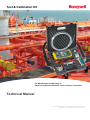
Test & Calibration Kit
For Maintenance and Servicing of
Electric and Electro-pneumatic Level / Pressure Transmitter
Technical Manual
SAS au Capital de 2 158 244 € - 444 871 933 R.C.S. Bourges - APE : 2651B
Headquarter : 9, rue Isaac Newton - 18000 Bourges - France
Test & Calibration Kit
Technical Manual
For Maintenance and Servicing of
Electric and Electro-pneumatic Level / Pressure Transmitter
1st Edition
Released February 2014
TABLE OF CONTENTS
1.
INTRODUCTION .............................................................................................................................4
2.
KIT DESCRIPTION .........................................................................................................................4
3.
OPERATION ...................................................................................................................................5
3.1. CT100M, CT150, CT180 ..........................................................................................................5
3.2 CT801, CT801LB/S ...................................................................................................................5
3.3 CT700 .......................................................................................................................................5
3.4 PL3700-PL3700 C .....................................................................................................................6
3.5 T901P........................................................................................................................................6
3.6 Temperature transmitter line ......................................................................................................7
4.
INFORMATION ...............................................................................................................................7
4.1 Reference of Honeywell Marine Customer Service ....................................................................7
4.2 Personal Notes ..........................................................................................................................8
1. INTRODUCTION
Specially designed for the maintenance, servicing and calibration of Honeywell Marine's
pneumatic, electro-pneumatic and electric transmitters, this Test & Calibration kit is provided with
all necessary accessories and instruments insuring quick and efficient operation.
2. KIT DESCRIPTION
The Test & Calibration kit is contained in a black polypropylene suitcase with shoulder strap. It is
composed of :
●
●
●
●
●
●
●
●
●
●
A pressure calibrator model 718-30G, including pressure generation range –850 to 2200 mbar
relative, with integrated pump, together with an electric current measurement, with 24 Vdc loop
power;
A set of spare batteries for above;
A flow meter for bubbling transmitters, with coupling for 4 x 6 mm tube;
A set of pneumatic couplings and tube :
- 2 couplings 1/4" for 4 x 6 mm tube;
- 3 couplings 1/8" for 4 x 6 mm tube;
- 1 coupling 3/8", with coupling for 4 x 6 mm tube;
- 2 dual coupling for 4 x 6 mm tube;
- 1 Te shape coupling for 4 x 6 mm tube;
- 3 meter 4 x 6 mm transparent plastic tube;
- 0.5 meter 4 x 6 mm soft transparent plastic tube;
An interface tool for PL3700-PL3700 C level/pressure transmitter calibration (except flange
welded models), composed of nut with coupling for 4 x 6 mm tube, , and screw, and adaptation
reduction, ref 35629
An interface tool for the pressure sensor of T901P transmitter, with coupling for 4 x 6 mm tube,
ref. T29195;
An equipped resistance of 100 ohms 3 wires for temperature transmitter's line test, ref.
T29235;
A set of specialized tools for above transmitters :
- 7 mm spanner mixt type;
- 3 mm male hexagonal spanner;
- 4 mm male hexagonal spanner;
- 3/16" male hexagonal spanner;
- 1/4" male hexagonal spanner;
- 2.5 x 75 mm screwdriver;
- 3.5 x 100 mm screwdriver;
The User's Manual of the pressure calibrator model 718-30G;
The present MT5023E Manual.
The pressure calibrator model 718-30G is provided with its initial calibration certificate. Further
periodic calibrations are to be carried out in compliance with the User's Quality Assurance
program.
Refer to the calibrator own User Manual in order to look at the technical specifications and to
operate. The pneumatic output is to be equipped with a provided coupling 1/8" for 4 x 6 mm tube,
sealed with PTFE ribbon.
Doc No: MT5023E – Revision 4 – ENG
Test & Calibration Kit
Level / Pressure Transmitter Technical
Manual
4
3. OPERATION
3.1.
CT100M, CT150, CT180
CT100M is the pneumatic bubbling modulator. CT150 and CT180 are the level indicator gathering
the CT100M modulator with a mechanical pointer manometer.
The flow meter allows controlling the bubbling flow, while the calibrator allows to check the
efficiency and leakproofness of the over-pressure protection valve and to check the calibration.
Refer to the Technical Manual NT5004 for CT100M, Technical Manual CT150, Installation,
Operating and Maintenance Manual NT5001 for CT180.
To check the calibration :
●
●
●
Disconnect the manometer's pneumatic 4 x 6 mm tube from the pneumatic module outlet;
Connect the pneumatic output of the calibrator to the manometer input, using 4 x 6 mm tube
with dual coupling;
Proceed to the calibration by pressure generation from the calibrator. If the transmitter's
pressure range is higher than 2200 mbar, select another calibration point inside the calibrator's
range.
3.2.
CT801, CT801LB/S
CT801 is the electro-pneumatic bubbling level transmitter.
The flow meter allows controlling the bubbling flow, while the calibrator allows to check the
efficiency and leakproofness of the over-pressure protection and safety valves, and to check the
calibration. Refer to the Maintenance Manual CB322382 for CT801, or MM5019 for CT801LB/S.
To check the calibration :
●
●
●
●
●
●
Make sure to be allowed to proceed in compliance with current rules regarding hazardous
area;
Switch off the CT801 power supply;
Disconnect the 4-20 mA output wires from the CT801 electronic module terminals, and the
sensor's pneumatic tubes from the pneumatic module outlets;
Connect the pneumatic output of the calibrator to the high pressure input of the CT801's
sensor, using 4 x 6 mm tube with dual coupling;
Connect the electrical input of the calibrator to the CT801 electronic module terminals; use
loop power mode;
Proceed to the calibration by pressure generation from the calibrator while reading the current
value in mA. If the transmitter's pressure range is higher than 2200 mbar, select another
calibration point inside the calibrator's range.
When the range is lower than -850 mbar and when the tank is empty, it is possible to avoid
disconnection of the sensor, and to connect the pressure generator to the Inert Gas connection
using a 1/8" coupling; then proceed to calibration by vacuum generation.
3.3.
CT700
CT701 or CT702 is the electric pressure / level transmitter, CT700-R uses a remote electronic
module. Refer to the Installation and Maintenance Manual CB322409 or CB322535 for High
Temperature model.
Doc No: MT5023E – Revision 4 – ENG
Test & Calibration Kit
Level / Pressure Transmitter Technical
Manual
5
To check the calibration :
●
●
●
●
●
●
Make sure to be allowed to proceed in compliance with current rules regarding hazardous
area;
Switch off the CT700 power supply;
Disconnect the 4-20 mA output wires from the CT700 electronic module terminals or from the
remote electronic module for CT700-R;
Depending of the CT700 installation configuration, connect the pneumatic output of the
calibrator to the test pressure inlet on flange with provided couplings sealed with PTFE ribbon,
or to the pressure inlet of the CT700 after disassembly, using 4 x 6 mm tube with 3/8"
coupling, sealed with PTFE ribbon;
Connect the electrical input of the calibrator to the CT700 electronic module terminals or to the
remote electronic module for CT700-R; use loop power mode;
Proceed to the calibration by pressure generation from the calibrator while reading the current
calibration point inside the calibrator's range.
3.4.
PL3700-PL3700 C
PL3700 is the electric pressure / level transmitter. Refer to the Installation and Maintenance
Manual MM5090.
To check the calibration :
●
●
●
●
●
●
Make sure to be allowed to proceed in compliance with current rules regarding hazardous
area;
Switch off the PL3700 power supply;
Disconnect the 4-20 mA output wires from the PL3700 remote electronic module terminals;
Connect the pneumatic output of the calibrator using 4 x 6 mm tube, to the test pressure inlet
on flange with provided couplings sealed with PTFE ribbon, or to the pressure inlet of the
PL3700 screwed model, using the dedicated mechanical interface T35629 by taking care with
the gasket; for PL3700 C do not mount the adaptation reduction Ǿ 49.5mm.
Connect the electrical input of the calibrator to the PL3700 remote electronic module terminals;
use loop power mode;
Proceed to the calibration by pressure generation from the calibrator while reading the current
value in mA. If the transmitter's pressure range is higher than 2200 mbar, select another
calibration point inside the calibrator's range.
3.5.
T901P
T901-PXX is the temperature / pressure transmitter used in TA840 and EMx40 Radar gauging
system, for measurement of cargo's temperature and inert gas pressure. For that last function, it
includes a pressure module. Refer to the Manual MM5016.
To check the calibration of the pressure module :
●
●
●
●
●
●
Make sure to be allowed to proceed in compliance with current rules regarding hazardous
area;
Switch off the TA3840S (or TA840-I) power supply;
Disassemble the pressure sensor from the flange, unscrewing the two screws; screw the
sensor on the dedicated mechanical interface by taking care with the gasket;
Connect the pneumatic output of the calibrator using 4 x 6 mm tube, to the interface pressure
inlet;
Switch on the TA3840S (or TA840-I) power supply;
Proceed to the calibration by pressure generation from the calibrator while reading the
pressure value on the system Monitoring.
Doc No: MT5023E – Revision 4 – ENG
Test & Calibration Kit
Level / Pressure Transmitter Technical
Manual
6
3.6.
Temperature transmitter line
The 100 ohms 3 wires resistance allows to check a temperature transmitter line : connect the
resistance instead of the temperature transmitter output wires, and check that the reading is
0 ± 0.4 °C. If different, the line should be restored.
4. INFORMATION
4.1.
Reference of Honeywell Marine Customer Service
For any request or help you can contact Honeywell Marine customer's services at the
following references.
Tel: + 33 (0) 2.48.23.79.28
Fax: + 33 (0) 2.48.23.79.02
E-mail: [email protected]
For sending equipment to check or to repair:
Honeywell Marine SAS
Customer’s department
9 rue Isaac Newton
18000 BOURGES
FRANCE
Doc No: MT5023E – Revision 4 – ENG
Test & Calibration Kit
Level / Pressure Transmitter Technical
Manual
7
4.2
Personal Notes
Doc No: MT5023E – Revision 4 – ENG
Test & Calibration Kit
Level / Pressure Transmitter Technical
Manual
8
Honeywell Marine SAS
9, Rue Isaac Newton
18000 Bourges
France
Tel + 33 (0) 2 48 23 79 01
Fax + 33 (0) 2 48 23 79 03
E-mail: [email protected]
www.honeywellprocess.com
MT5023E-rev04-ENG
February 2014
© 2014 Honeywell International Inc.