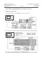
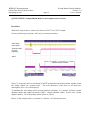
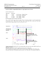
1
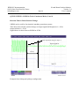
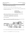
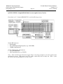
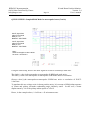
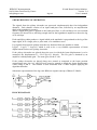
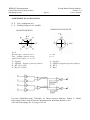
Bergoz Instrumentation
Espace Allondon Ouest
01630 Saint Genis Pouilly, France
Tel. : +33-450.426.642
Fax : +33-450.426.643
S-band
Beam Position Monitor
User’s Manual
Rev. 2.4
Includes
Processing modes:
Auxiliary options:
Accessories:
Sample & Hold
Track & Hold
Track-Continuous
Beam Trigger, built-in
Sum-of-log Output
Direct log (A,B,C,D) outputs
Filter/amplifier Front-end
Japan:
U.S.A.:
REPIC Corporation
28-3, Kita Otsuka 1-Chome
Toshima-ku, Tokyo 170-0004
Tel.: 03 - 3918 - 5326
Fax: 03 - 3918 - 5712
GMW Associates
955 Industrial Road
San Carlos, CA 94070
Tel.: (650) 802-8292
Fax: (650) 802-8298
BERGOZ Instrumentation - 01630 Saint Genis Pouilly, France - Tel.: +33-450.426.642 - Fax: +33-450.426.643
[email protected] - http://www.bergoz.com - Registre des Métiers: Bourg-en-Bresse - Registre des ingénieurs: Zurich
TVA-VAT-IVA-USt. Nº FR88414997130 - Sàrl. capital 152K€ - Siren 414 997 130 R.C.S. Bourg - APE 2651B
Record of updates
Version
Release date
1.0
December 8, 2008
Initial version derived from LR-BPM User’s Manual v. 2.2.1
S-BPM 111.3.1
1.1
January 16, 2009
Layout change
1.3
February 18, 2010
Layout change
S-BPM CONNECTORS PINS ALLOCATION change
1.4
March 09, 2010
T&H ; S&H Timing change
T&H ; S&H graphs added
p. 44 TRG.IN.AUX negative edge correction
p. xx Pin AlloCATION correction DB9, 9 => TRG.ADC.OUT
2.0
April 01, 2011. S-BPM new release: 111.3.2. Main changes:
S-BPM layout change (switch positions)
Track Continuous reptition rate up to 10MHz instead of 5MHz
Sample & Hold 400ns processing time instead of 470ns
Sample & Hold repetition rate 5KHz instead of 2MHz due to trigger inhibition
SUMOUT positive value instead of negative
TRG.AUX.IN on rising edge > 0.4V instead of negative > 2V
Ortho. / Rot. jumpers positions as LR-BPM
Track Continuous traces
Track & Hold and Sample & Hold traces
Resolution improvements
CONNECTORS PINS ALLOCATION Rev. 1.2 (TRG.ADC.OUT DB9 pin5)
2.1
April 26, 2011
p.43 "Agreement on axes & signs", schematics and annotations corrections.
2.2
May 23, 2011
Correction T / T&H S&H mode switch position p.12, 13 & 15.
2.3
March 12, 2012
Reaction Time to Beam Position Change p.28 => updated
2.4
November 07, 2013
CONNECTORS PINS ALLOCATION Rev. 1.3 (errors correction)
BERGOZ Instrumentation
01630 Saint Genis Pouilly, France
[email protected]
Page 1
S-band Beam Position Monitor
Version 2.4
User’s manual
SUMMARY
INITIAL INSPECTION, WARRANTY, ASSISTANCE......................................................................................2
YOU JUST RECEIVED A BEAM POSITION MONITOR ................................................................................3
Determine which S-BPM model you received.....................................................................................5
Determine which options are installed onto S-BPM............................................................................5
MODES OF OPERATION FOR VARIOUS BEAMS..........................................................................................7
Track-Continuous (T) Mode.................................................................................................................7
Sample & Hold (S&H) Mode...............................................................................................................8
Track & Hold (T&H) Mode.................................................................................................................8
Triggering.............................................................................................................................................9
Switching between modes....................................................................................................................9
OPTIONS............................................................................................................................................................10
Built-in Beam Trigger “S-BPM-TRG” option...................................................................................10
Sum of logs Output “S-BPM-SUM” option.......................................................................................10
Direct log outputs for A, B, C and D “S-BPM-ABCD” option.........................................................10
ACCESS to JUMPERS and SWITCHES............................................................................................................11
TRACK-CONTINUOUS MODE.......................................................................................................................12
TRACK and HOLD MODE................................................................................................................................13
TRACK & HOLD MODE (Con't)......................................................................................................................14
SAMPLE & HOLD MODE................................................................................................................................15
CHANGING PICKUP CONFIGURATION.......................................................................................................17
Orthogonal pickups, position of jumpers...........................................................................................17
Rotated pickups, position of jumpers.................................................................................................17
QUICK CHECK: S-BPM in Track-Continuous Mode.......................................................................................18
For CW beams....................................................................................................................................18
Beam displacement.............................................................................................................................20
Dynamic range....................................................................................................................................20
For macropulse beam.........................................................................................................................21
Simulating beam position changes.....................................................................................................23
Resolution...........................................................................................................................................25
Dynamic range....................................................................................................................................26
Reaction Time to Beam Position Change...........................................................................................28
QUICK CHECK: S-BPM in Sample&Hold Mode.............................................................................................29
For macropulse beam.........................................................................................................................29
Timing for macropulse beam..............................................................................................................33
Resolution...........................................................................................................................................35
For single pulse beam.........................................................................................................................36
Simulating beam position changes.....................................................................................................40
S-BPM PRINCIPLE OF OPERATION...............................................................................................................42
BLOCK DIAGRAM...........................................................................................................................................42
AGREEMENT ON AXES & SIGNS..................................................................................................................43
SIGNALS............................................................................................................................................................44
S-BPM CONNECTORS PINS ALLOCATION Rev. 1.3...................................................................................46
BPM CABLES LAYOUT INSTALLATION......................................................................................................47
Cable layout........................................................................................................................................47
ACCESSORIES..................................................................................................................................................48
Font-End Filter/Amplifier (S-FEFA)..................................................................................................48
Table-top test kit (BPM-KIT).............................................................................................................48
Card Extender BPM-XTD.................................................................................................................49
Power Supply module.........................................................................................................................50
BPM Chassis BPM-RFC/X................................................................................................................50
SCHEMATICS & BOARD LAYOUT................................................................................................................52
ACKNOWLEDGEMENTS................................................................................................................................52
BERGOZ Instrumentation
01630 Saint Genis Pouilly, France
[email protected]
Page 2
S-band Beam Position Monitor
Version 2.4
User’s manual
INITIAL INSPECTION, WARRANTY, ASSISTANCE
INITIAL INSPECTION
It is recommended that the shipment be inspected immediately upon delivery. If it is damaged
in any way, contact Bergoz Instrumentation or your distributor. The content of the shipment
should be compared to the items listed on the invoice. Any discrepancy should be notified to
Bergoz Instrumentation or its distributor immediately. Unless promptly notified, Bergoz
Instrumentation will not be responsible for such discrepancies.
WARRANTY
Bergoz Instrumentation warrants its beam monitors to operate within specifications under
normal use for a period of 12 months from the date of shipment. Spares, repairs and
replacement parts are warranted for 90 days. Products not manufactured by Bergoz
Instrumentation are covered solely by the warranty of the original manufacturer. In exercising
this warranty, Bergoz Instrumentation will repair, or at its option, replace any product returned
to Bergoz Instrumentation or its distributor within the warranty period, provided that the
warrantor’s examination discloses that the product is defective due to workmanship or
materials and that the defect has not been caused by misuse, neglect, accident or abnormal
conditions or operations. Damages caused by ionizing radiations are specifically excluded
from the warranty. Bergoz Instrumentation and its local distributors shall not be responsible for
any consequential, incidental or special damages.
ASSISTANCE
Assistance in installation, use or calibration of Bergoz Instrumentation beam monitors is
available from Bergoz Instrumentation, 01630 Saint Genis Pouilly, France. It is recommended
to send a detailed description of the problem by e-mail.
SERVICE PROCEDURE
Products requiring maintenance should be returned to Bergoz Instrumentation or its distributor.
Bergoz Instrumentation will repair or replace any product under warranty at no charge. The
purchaser is only responsible for transportation charges.
For products in need of repair after the warranty period, the customer must provide a purchase
order before repairs can be initiated. Bergoz Instrumentation can issue fixed price quotations
for most repairs. However, depending on the damage, it may be necessary to return the
equipment to Bergoz Instrumentation to assess the cost of repair.
RETURN PROCEDURE
All products returned for repair should include a detailed description of the defect or failure and
name of the user. Contact Bergoz Instrumentation or your local distributor to determine where
to return the product. Returns must be notified by e-mail prior to shipment.
Return should be made prepaid. Bergoz Instrumentation will not accept freight-collect
shipment. Shipment should be made via United Parcel Service, DHL or Federal Express.
Within Europe, the transportation service offered by the Post Offices “EMS” (Chronopost,
Datapost, etc.) can be used. The delivery charges or customs clearance charges arising from the
use of other carriers will be charged to the customer.
BERGOZ Instrumentation
01630 Saint Genis Pouilly, France
[email protected]
S-band Beam Position Monitor
Version 2.4
User’s manual
Page 3
YOU JUST RECEIVED A BEAM POSITION MONITOR ....
This manual applies to the S-band BPM only: S-BPM 111.3.2
Other models, e.g. BPM, MX-BPM, LR-BPM, VF-BPM, BB-BPM, BPM-AFE are described
in other manuals.
The S-band BPM system includes:
Description
Order code
•
•
•
•
•
S-BPM/X.XXXGHz
S-BPM-SH
S-BPM-TRG
S-BPM-SUM
S-BPM-ABCD
S-band BPM electronics module
Sample & Hold on X and Y, option
Beam Trigger, option
Sum of logs, option
Direct A,B,C,D wideband outputs, option
The options are factory-installed onto the S-BPM electronics module.
Accessories
• Filter/Amplifer Front-end (1 channel)
• 19” chassis with power supply
• Table-top test kit
• 3U-Card extender with coaxial contacts
• RF service module with four front-panel BNC
S-FEFA/X.XXXGHz
BPM-RFC/X,
X = number of BPM stations
BPM-KIT
BPM-XTD
BPM-SERV/RF
BERGOZ Instrumentation
01630 Saint Genis Pouilly, France
[email protected]
Page 4
S-band Beam Position Monitor
Version 2.4
User’s manual
YOU JUST RECEIVED A BEAM POSITION MONITOR ....
Check that the Table-top Kit power supply voltage corresponds to your mains voltage.
On some table-top kit BPM-KIT older models, an AC/DC power supply block is installed. Its
AC input voltage range is indicated on the power supply block. If it does not correspond to
your AC mains, use a transformer or contact the manufacturer to get another power supply.
In the 19” chassis BPM-RFC: The power supply is autoranging from 98V…264V.
Check the fuse configuration, that it corresponds to your national regulations.
The table-top test kit does not have any fuse.
The 19” BPM-RFC chassis fuse compartment is configured at the time of shipment according
to its destination:
• North America: mains ground wire unfused.
• All other destinations: both mains wires are fused.
To verify which fuse configuration is installed on your chassis, pull out the removable fuse
block, using a small screwdriver.
• The unfused ground configuration has a shorting bar and a 2A 6x32 fuse.
• The configuration with both AC lines fused is equipped with two 2A 5x20 fuses.
To change this configuration, unscrew the fuse holder off the fuse block, flip the holder over
and screw it back onto the fuse block. Insert the following fuses:
• For unfused ground configuration: one 2A 6x32 fast fuse.
• For both AC lines fused configuration: two 2A 5x20 fast fuses.
BERGOZ Instrumentation
01630 Saint Genis Pouilly, France
[email protected]
Page 5
S-band Beam Position Monitor
Version 2.4
User’s manual
YOU JUST RECEIVED A BEAM POSITION MONITOR ....
Determine which S-BPM model you received
At the time of writing this User’s Manual, only one version has been shipped to users: S-BPM
revision number 111.3.2
The circuit revision number 111.3.2 is engraved on the printed circuit board.
Determine which options are installed onto S-BPM
S-BPM with option Sample & Hold i.e. S-BPM-SH can be recognized by:
• The printed circuit is equipped with Track&Hold + Sample&Hold circuits:
To remove the shield cover, refer to Chapter ACCESS TO JUMPERS and SWITCHES.
Track & Hold + Sample & Hold circuits
BERGOZ Instrumentation
01630 Saint Genis Pouilly, France
[email protected]
Page 6
S-band Beam Position Monitor
Version 2.4
User’s manual
YOU JUST RECEIVED A BEAM POSITION MONITOR ....
Determine which options are installed (Cont’d)
Buit-in trigger circuit
S-BPM with Built-in Trigger option S-BPM-TRG can be recognized by:
• The printed circuit board is equipped with a built-in trigger circuit:
S-BPM with A,B,C and D direct outputs option S-BPM-ABCD can be recognized
• The printed circuit board is equipped with A, B, C and D output connectors
Direct output connectors for Channels A, B, C, D
LOGA
LOGB
LOGC
LOGD
BERGOZ Instrumentation
01630 Saint Genis Pouilly, France
[email protected]
Page 7
S-band Beam Position Monitor
Version 2.4
User’s manual
MODES OF OPERATION FOR VARIOUS BEAMS
S-BPM can be equipped with many options, then further configured by the user to support
many modes of operation:
Track-Continuous (T) Mode
Does not require Sample & Hold option
Does not require Built-in Beam Trigger option
Output bandwidth
DC to 10 MHz
T-mode is indicated whenever fast beam motion must be observed:
• CW beams in general
• Linacs and synchrotrons with bunch repetition rate up to 3 GHz
• Betatron oscillation monitoring in boosters and storage rings
• Cyclotrons, microtrons
• Ion and proton synchrotrons with ƒrev > 1 MHz
Note : Track & Hold can also be used up to 5 MHz frev.
Macropule beams:
• Linacs with micropulse RF structure up to 3 GHz
• Transfer lines with micropulse RF structure up to 3 GHz
• Cyclotrons, microtrons
The Track Continuous mode is NOT suitable for single bunch beams, i.e. Beams of short pulses
at low repetition rate. E.g. pulses at 10 Hz repetition rate. To measure these beams, the Sample
& Hold mode must be used.
Refer to “Sample & Hold Mode” chapter p.15 for switch settings.
BERGOZ Instrumentation
01630 Saint Genis Pouilly, France
[email protected]
Page 8
S-band Beam Position Monitor
Version 2.4
User’s manual
MODES OF OPERATION FOR VARIOUS BEAMS (Cont’d)
Sample & Hold (S&H) Mode
Requires Sample&Hold option S-BPM-SH to be mounted on the printed circuit board
Processing time
Hold time
ADC measurement time
Repetition rate
~ 400 ns
Up to 100 ms.
At maximum repetion rate, at least 100 ns “good signal”.
Limited to 5kHz by on-board trigger inhibition.
Note that T&H Mode can be used, up to 5 MHz, when the pulse or macropulse repetition rate is
higher than 1 MHz.
Linacs: single bunch, macropulses, bunch trains
Transfer lines: single bunch, macropulses, bunch trains
Synchrotron first turn
Synchrotron single bunch turn-by-turn
Synchrotron multi-single bunch turn-by-turn, using trigger gate.
Refer to “Sample & Hold Mode” chapter p.15 for switch settings
Track & Hold (T&H) Mode
Requires Sample&Hold option S-BPM-SH to be mounted on the printed circuit board
Processing time
Hold time
ADC measurement time
Repetition rate
~ 60 ns
~ 70 ns
At maximum repetion rate, at least 50 ns “good” signal
Up to 5 MHz
Indicated whenever the single pulse or macropulse repetition rate is faster than 2 MHz.
Note that T&H Mode cannot be used when the pulse or macropulse repetition rate is higher
than 5 MHz.
Indicated for:
Linacs, Synchrotron ƒrev < 5 MHz,
Single bunch turn-by-turn
Synchrotron multi-single bunch turn-by-turn, using trigger gate.
Refer to " Track & Hold Mode” chapter p.13 for switch settings
BERGOZ Instrumentation
01630 Saint Genis Pouilly, France
[email protected]
Page 9
S-band Beam Position Monitor
Version 2.4
User’s manual
MODES OF OPERATION FOR VARIOUS BEAMS (Cont’d)
Triggering
In Sample&Hold (S&H) and Track&Hold (T&H) modes, S-BPM must be triggered.
Triggering can be provided:
a) by the built-in Beam Trigger, if installed on S-BPM (order code S-BPM-TRG).
To use the built-in Beam Trigger, it must be enabled by its switch.
See built-in Beam Trigger switch p.12.
b) by an external signal applied to TRG.IN.AUX input.
To use the external trigger, the built-in trigger –if installed– must be disabled.
See built-in Beam Trigger switch p.12.
Switching between modes
In principle, the Mode of Operation is set by the on-board switches, permanently.
Yet, it is possible during operation, to switch to Track-Continuous Mode to ease the timing
adjustment of an external trigger. The control line TRACK-CONTINUOUS (pull down) is
available on the front panel DB9 pin 7.
BERGOZ Instrumentation
01630 Saint Genis Pouilly, France
[email protected]
Page 10
S-band Beam Position Monitor
Version 2.4
User’s manual
OPTIONS
In addition to the Sample & Hold option described in the preceeding chapter, other options are
available:
Built-in Beam Trigger “S-BPM-TRG” option
Requires Built-in Beam Trigger option S-BPM-TRG to be mounted on the printed circuit board
Particle polarity
Minimum detected charge
Maximum repetition rate
S-BPM operates with positive and negative particle
polarity
100 pC bunch seen by four pickups of 5 pF capacitance and
width = 1/8 of circumference.
5 MHz.
Sum of logs Output “S-BPM-SUM” option
Requires Sum-of-Logs option S-BPM-SUM to be mounted on the printed circuit board
Value
Bandwidth
SUM = +[Lg(A) + Lg(B) + Lg(C) + Lg(D)]
10 MHz
Note: When the beam is on center of the BPM pickup, Lg(A) = Lg(B) = Lg(C) = Lg(D), thus
SUM is proportional to +Lg(beam current).
Direct log outputs for A, B, C and D “S-BPM-ABCD” option
Requires Direct A,B,C,D Outputs option S-BPM-ABCD to be mounted on the printed circuit
board
Outputs
Bandwidth
Connectors
Log(A), Log(B), Log(C) and Log(D)
10 MHz
1.0/2.3 output connectors
Note: Mating connectors are not installed in chassis BPM-RFC
or BPM-KIT.
Users of option S-BPM-ABCD must provide
these connectors. Refer to “BPM MODULE REAR
CONNECTOR”.
See typical Lg(A) output from a single bunch on preceeding page timing diagram.
Note: Accessories are described in chapter p.48 “ACCESSORIES”.
BERGOZ Instrumentation
01630 Saint Genis Pouilly, France
[email protected]
Page 11
S-band Beam Position Monitor
Version 2.4
User’s manual
ACCESS to JUMPERS and SWITCHES
To access jumpers and switches, remove the module shield:
S-BPM modules can be inserted/removed from their chassis or BPM-KIT while the power is ON.
The S-BPM module is equipped with many on-board potentiometers to adjust the log
amplifiers gain, slope and intercept point. They require precise instruments, tools and
procedures for their adjustment.
BERGOZ Instrumentation
01630 Saint Genis Pouilly, France
[email protected]
S-band Beam Position Monitor
Version 2.4
User’s manual
Page 12
TRACK-CONTINUOUS MODE
Set switches to:
Mode: Track-Continuous (T) => DOWN
Processing: Track-Continuous (T) => UP
Timing: Inactive
Built-in Beam Trigger: not available in this mode
TRG.ADC.OUT Edge : not available in this mode
Active switch
Inactive switch
Built-in Beam
Trigger
UP / DOWN
Enabled / Disabled
Processing
UP
T&H or T
DOWN
S&H
TRG.ADC.OUT Edge
Mode
In S&H Mode :
UP
/ DOWN
Negative / Positive
In T&H Mode :
UP
/ DOWN
Positive / Negative
UP :
T
Timing
UP / DOWN
T&H / S&H
DOWN :
S&H or T&H
Output signals XOUT and YOUT track the position given by A, B, C and D inputs with DC to
10 MHz bandwidth.
BERGOZ Instrumentation
01630 Saint Genis Pouilly, France
[email protected]
Page 13
S-band Beam Position Monitor
Version 2.4
User’s manual
TRACK and HOLD MODE
Set switches to:
Mode: T&H => UP
Processing: T&H => UP
Timing Hold Clock: T&H => UP
Timing Trigger: Inhibition Trigger to avoid bad trigger during
processing. 200ns in T&H mode => UP
Built-in Beam Trigger as desired. Disable for external trigger.
ADC Trigger Output Edge as desired
Active switch
Inactive switch
Built-in Beam
Trigger
UP / DOWN
Enabled / Disabled
Processing
UP
T&H or T
DOWN
S&H
TRG.ADC.OUT Edge
In S&H Mode :
UP
/ DOWN
Negative / Positive
In T&H Mode :
UP
/ DOWN
Positive / Negative
Mode
Timing Hold Clock
UP / DOWN
T&H / S&H
UP :
T
DOWN :
S&H or T&H
BERGOZ Instrumentation
01630 Saint Genis Pouilly, France
[email protected]
Page 14
S-band Beam Position Monitor
Version 2.4
User’s manual
TRACK & HOLD MODE (Con't)
In Track & Hold Mode, the output signals timing looks like this:
3GHz input
macropule
TRG.ADC.OUT
for Oscilloscope
triggering
(on falling edge)
~70 ns “Good” XOUT and
YOUT signals
XOUT
Output signals XOUTand YOUT track the position given by A, B, C and D inputs with 5 MHz
bandwidth.
With 5MHz macropulse repetition rate, the output signals looks like this :
5 MHz repetition rate
200 ns
3GHz input
macropule
TRG.ADC.OUT
for oscilloscope
triggering
(on falling edge)
XOUT
BERGOZ Instrumentation
01630 Saint Genis Pouilly, France
[email protected]
Page 15
S-band Beam Position Monitor
Version 2.4
User’s manual
SAMPLE & HOLD MODE
Set switches to:
Mode: Sample&Hold => UP
Processing: Sample&Hold => DOWN
Timing Hold Clock: Sample&Hold => DOWN
Timing Trigger: Inhibition Trigger to avoid bad trigger during
processing. 200us in S&H mode => DOWN
Built-in Beam Trigger: As desired
ADC Trigger Output Edge: As desired
Active switch
Inactive switch
Built-in Beam
Trigger
UP / DOWN
Enabled / Disabled
Processing
UP
T&H or T
DOWN
S&H
TRG.ADC.OUT Edge
In S&H Mode :
UP
/ DOWN
Negative / Positive
In T&H Mode :
UP
/ DOWN
Positive / Negative
Mode
Timing Hold Clock
UP / DOWN
T&H / S&H
UP :
T
DOWN :
S&H or T&H
BERGOZ Instrumentation
01630 Saint Genis Pouilly, France
[email protected]
Page 16
S-band Beam Position Monitor
Version 2.4
User’s manual
SAMPLE & HOLD MODE (Cont’d)
In Sample & Hold Mode, the output signals timing looks like this:
3GHz input
macropule
TRG.ADC.OUT
for oscilloscope
triggering
From TRG.ADC.OUT trailing
edge, XOUT is good to be read
by ADC
XOUT
Good value on XOUT
~400ns
Trailing edge of TRG.ADC.OUT occurs about 400ns from the time when TRG.IN.AUX was
applied to S-BPM.
XOUT (and YOUT) are good to read by ADC at the time of TRG.ADC.OUT trailing edge.
Note that TRG.ADC.OUT polarity can be inverted.
The timing is explained in more details in
QUICK CHECK: S-BPM in Sample & Hold Mode: Timing for macropulse
beam p.33
BERGOZ Instrumentation
01630 Saint Genis Pouilly, France
[email protected]
Page 17
S-band Beam Position Monitor
Version 2.4
User’s manual
CHANGING PICKUP CONFIGURATION
The pickup configuration is set with two jumpers.
To change the configuration from “Rotated” to “Orthogonal” or vice versa, change the jumper
position:
Orthogonal pickups, position of jumpers
Jumpers position for
“Orthogonal” pickups
Rotated pickups, position of jumpers
Jumpers position for
“Rotated” pickups
BERGOZ Instrumentation
01630 Saint Genis Pouilly, France
[email protected]
Page 18
S-band Beam Position Monitor
Version 2.4
User’s manual
QUICK CHECK: S-BPM in Track-Continuous Mode
Track-Continuous mode can be used on CW beam or macropulse (burst) mode. A Quick Check
is described for both modes, successively.
For CW beams
If you wish to use an S-BPM (whether or not it has the Sample & Hold option S-BPM-SH), its
switches must be set according to chapter TRACK-CONTINUOUS MODE. Unless otherwise
specified, S-BPM without Sample&Hold S-BPM-SH option has following ex-factory settings:
•
•
•
•
Orthogonal pickups
Mode: Track-Continuous
Built-in trigger: Disabled
ADC Trigger output: positive edge
Setup, to check immediately that your S-BPM system is working.
If you have the table-top test kit (BPM-KIT), use the following set-up:
If you have a 19” chassis (BPM-RFC/X), use the following set-up:
BERGOZ Instrumentation
01630 Saint Genis Pouilly, France
[email protected]
Page 19
S-band Beam Position Monitor
Version 2.4
User’s manual
QUICK CHECK: Track-Continuous Mode for CW beam (Cont’d)
To display X and Y signals, use an oscilloscope.
Attach the equipment together as shown above.
Oscilloscope setup:
Time base
1 us/div.
CH1
0.2 V/div.
CH2
0.2 V/div.
Trigger: free running
DC-1 Mohm XOUT
DC-1 Mohm YOUT
Set the RF source to the S-BPM operating frequency.
E.g. Set to 2856 MHz to test S-BPM/2856MHz.
Amplitude about -20 dBm
Please note that signals applied to S-FEFA inputs will be attenuated by the 4-way splitter:
Inductive-type 4-way splitters typically attenuate by 7dB,
4-way resistive splitters, or cascaded 2-way splitters attenuate by 12dB.
Connect Test Kit to DC supply or BPM-RFC chassis to AC mains; the oscilloscope will display
X and Y values.
XOUT signal from
either Front Panel
DB9 pin 1 or
BPM-KIT XOUT BNC
YOUT signal from
either Front Panel
DB9 pin 1 or
BPM-KIT YOUT BNC
Note :
XOUT and YOUT
signals overlap.
Observe RMS signal
noise (sdev).
If the RF signals applied to all four S-FEFA inputs were exactly equal, and if the S-FEFA and
S-BPM modules were perfect, the XOUT and YOUT voltages would be exactly 0 Volt.
This is generally not the case, X and Y will be many 10s of millivolts off.
To determine how much of this offset is caused by power splitter imbalance:
Instead of connecting S-FEFA “A” to power splitter output 1, connect it to output 3.
Do the same for S-FEFA B and D with power splitter outputs 2 and 4.
BERGOZ Instrumentation
01630 Saint Genis Pouilly, France
[email protected]
Page 20
S-band Beam Position Monitor
Version 2.4
User’s manual
QUICK CHECK: Track-Continuous Mode for CW beam (Cont’d)
The next tests consists of simulating beam displacements
Insert a 6-dB attenuator at any power splitter output (e.g., signal to A input)
The RF source output power should be in the range -10dBm ... -35 dBm
XOUT signal from
either Front Panel
DB9 pin 1 or
BPM-KIT XOUT BNC
YOUT signal from
either Front Panel
DB9 pin 1 or
BPM-KIT YOUT BNC
Note :
Observe XOUT signals is
shifted to above -347mV
due to the 6dB attenuator
in input A.
Further tests can be performed:
Beam displacement
• Simulating beam displacements along the X or Y axes (or both) with various attenuator
values.
Refer to BEAM DISPLACEMENT chapter.
Dynamic range
The dynamic range can be tested: Simulate a higher or lower beam current by varying the RF
source output power.
Also refer to DYNAMIC RANGE chapter.
BERGOZ Instrumentation
01630 Saint Genis Pouilly, France
[email protected]
Page 21
S-band Beam Position Monitor
Version 2.4
User’s manual
QUICK CHECK: Track-Continuous Mode
For macropulse beam
If the RF power source can be gated, apply a gate to the RF source to simulate macropulses.
Apply the same gate signal to the oscilloscope trigger input.
Setup. If you have the table-top test kit (BPM-KIT), use the following set-up:
If you have a 19” chassis (BPM-RFC/X), use the following set-up:
BERGOZ Instrumentation
01630 Saint Genis Pouilly, France
[email protected]
Page 22
S-band Beam Position Monitor
Version 2.4
User’s manual
QUICK CHECK: Track-Continuous Mode
For macropulse beam (Cont’d)
The Gate duration is set to 5 us. The gating frequency is set to 1 kHz.
Try faster gating frequency: The macropulse repetition rate can be very high.
The following screen shot does not show the macropulse. It shows the S-BPM output signals
XOUT and YOUT.
Observe high amplitude output noise on XOUT and YOUT before and after the 5-us
macropulse. This high noise is caused by the amplifiers going into high gain when there is no
input signal.
XOUT signal from
either Front Panel
DB9 pin 1 or
BPM-KIT XOUT BNC
YOUT signal from
either Front Panel
DB9 pin 1 or
BPM-KIT YOUT BNC
Note :
Observe XOUT signals is
shifted to above -347mV due
to the 6dB attenuator
in input A.
Observe high noise before
and after macropulse due to
amplifiers going to highest
gain when there is no input.
BERGOZ Instrumentation
01630 Saint Genis Pouilly, France
[email protected]
Page 23
S-band Beam Position Monitor
Version 2.4
User’s manual
QUICK CHECK: S-BPM in Track-Continuous Mode (Cont’d)
Simulating beam position changes
To simulate beam position changes, the input signal power is changed by 6 dB, 10 dB and 14
dB, hence simulating position changes up to 1/3 of BPM pickup radius.
The S-BPM on-center sensitivity is factory-set to 55.5 mV per dB of signal difference between
opposite pickups. For pickups with small subtending angle (e.g. Buttons), 6 dB corresponds to
beam displacement equal to 1/6 of BPM pickup radius. As the beam goes far off center, this
sensitivity becomes lower due to the algorithm X = Log (A/C). Please consider that the pickup
sensitivity becomes higher as the beam goes off center, and one non-linearity tends to
compensate the other.
Before simulating a beam displacement, write down the XOUT and YOUT zero offsets, using
four equal attenuators:
Then simulate the displacement by removing an attenuator from one input and inserting it in the
opposite input: A <=> C, and B <=> D.
Example:
Attenuator C is removed from input C, and added to input A, thus simulating a displacement of
the beam towards C (stronger signal on C pickup).
S-BPM modules are factory preset :
• For orthogonally placed pickups: A=up, B=left, C=down, and D=right; or,
• For rotated pickups: A=upper-right, B=upper-left, C=lower-left and D=lower-right.
The combinations on the following table can be tried, yielding the X and Y values listed.
Please note these are displacements. Take into consideration the zero offsets due to power
splitter imbalance and attenuators inequality.
BERGOZ Instrumentation
01630 Saint Genis Pouilly, France
[email protected]
S-band Beam Position Monitor
Version 2.4
User’s manual
Page 24
QUICK CHECK: S-BPM in Track-Continuous Mode (Cont’d)
Beam displacement (Cont’d)
Table of X/Y output voltage vs. input power, assuming the pickup subtending angle is infinitely
small.
Input Attenuators
A
B
C
D
3+3
3
0
3
A
B
C
D
3+3
3+3
0
0
A
B
C
D
5+5
5
0
5
A
B
C
D
5+5
5+5
0
0
A
B
C
D
10 + 7
10
3
10
Equivalent
Displacement
Orthogonal
pickups
Rotated pickups
1/6 of Radius towards C
X = -0,245 V
Y = -0,245 V
X = -0,347 V
Y=0V
1/6 of Radius towards C
1/6 of Radius towards D
X= 0V
Y = -0,490 V
X = -0,347 V
Y = -0,347 V
1/4 of Radius towards C
X = -0,407 V
Y = -0,407 V
X = -0,576 V
Y=0V
1/4 of Radius towards C
1/4 of Radius towards D
X= 0V
Y = -0,814 V
X = -0,576 V
Y = -0,576 V
1/3 of Radius towards C
X = -0,570 V
Y = -0,570 V
X = -0,806 V
Y= 0V
Please note these are displacements. Take into consideration the zero offsets due to power
splitter imbalance and attenuators inequality.
Note. The above voltages are representations of the algorithms:
For Orthogonal pickups:
X = Kx Lg(A/C) and Y = Ky Lg(B/D)
For Rotated pickups:
X = Kx [Lg(A/C) – Lg(B/D)] cos(β), and Y = Ky [Lg(A/C) + Lg(B/D)] sin(β).
Where: β is the tilt angle of the pickup axes. Refer to AGREEMENT on AXES and SIGNS
p.43.
Kx.cos(β) and Ky.sin(β) are factory-set to 1.1513 Volts
Note: This value was chosen because it corresponds to a difference-over-sum ratio equal to 1
for small amplitude displacements off-center. E.g. 0.001 V for 0.005 x R.
BERGOZ Instrumentation
01630 Saint Genis Pouilly, France
[email protected]
Page 25
S-band Beam Position Monitor
Version 2.4
User’s manual
QUICK CHECK: Track-Continuous Mode
Resolution
The noise spectrum of XOUT (or YOUT) indicates the resolution attainable by S-BPM.
Connect an oscilloscope to XOUT (or YOUT).
Plot in histogram mode (e.g., Lecroy SDA11000)
Blue :
XOUT signal from
either Front Panel
DB9 pin 1 or
BPM-KIT XOUT BNC
Yellow :
XOUT Standard deviation
distribution
The noise is about 1.6mVrms.
To translate this rms voltage noise in beam position resolution, let’s assume a 25mm vacuum
chamber radius and pickup electrodes width < vacuum chamber radius. In this case, a beam
displacement by 1/6 of the pickup radius equals to 347mV.
Hence, in the example above, 1.6 mVrms = 24 micrometers rms.
BERGOZ Instrumentation
01630 Saint Genis Pouilly, France
[email protected]
Page 26
S-band Beam Position Monitor
Version 2.4
User’s manual
QUICK CHECK: S-BPM in Track-Continuous Mode (Cont’d)
Dynamic range
Observe S-BPM dynamic range with a vector network analyser (VNA).
The measurements hereafter require a VNA equipped with an Auxiliary DC input, usually
placed at the rear. Some known models to feature such a DC auxiliary input are:
Agilent 8357D, E and ES, Agilent 5071C.
Setup
If you have the table-top test kit (BPM-KIT), use the following set-up:
If you have a 19” chassis (BPM-RFC/X), use the following set-up:
BERGOZ Instrumentation
01630 Saint Genis Pouilly, France
[email protected]
Page 27
S-band Beam Position Monitor
Version 2.4
User’s manual
QUICK CHECK: S-BPM in Track-Continuous Mode (Cont’d)
Dynamic range (Cont’d)
Set the VNA in power sweep mode, over the widest possible range.
To cover the full S-BPM dynamic range, the VNA must be capable of >50dB power sweep.
Successive power sweeps may be needed if the VNA has a more limited sweep range.
Perform several sweeps with various input attenuators combinations in such a way that X and Y
off center linearity is tested.
Explore the range from +7 dBm down to -70 dBm.
Remember that 4-way inductive-type splitters absorb typically 7 dB and resistive splitters
absorb 12 dB.
Usefull dynamic range about 52 dB
The plot above shows the dynamic range of S-BPM with 11-meter long input cables.
The ¼” cables used attenuate ≈100dB/100m at 3 GHz (Huber+Suhner GX03272).
A subjective evaluation would indicate a useful dynamic range of 52dB from Marker-1 to
Marker-2.
Operating limits with 11-meter cables: -50 dBm to 0 dBm (after adding 7dB to the markers
value in consideration of the 4-way inductive splitter insertion loss).
Note: -50 dBm is –approximately– the signal collected by a BPM electrode whose subtending
angle is 45 degrees, passed by a 100-uA CW beam.
BERGOZ Instrumentation
01630 Saint Genis Pouilly, France
[email protected]
Page 28
S-band Beam Position Monitor
Version 2.4
User’s manual
QUICK CHECK: S-BPM in Track-Continuous Mode (Cont’d)
Reaction Time to Beam Position Change
S-BPM can be used for fast interlock machine protection systems:
Time delay from a beam position change to Output signal half-height rise is ~45 ns
Output risetime is ~30 ns.
Signal shown is taken from an S-BPM at 3GHz.
Signal Amplitude change on input A
Input signal A
~45 ns
XOUT
Example from Orthogonal pickups configuration.
BERGOZ Instrumentation
01630 Saint Genis Pouilly, France
[email protected]
Page 29
S-band Beam Position Monitor
Version 2.4
User’s manual
QUICK CHECK: S-BPM in Sample&Hold Mode
This Quick Check works only if Sample & Hold S-BPM-SH option is installed
Unless otherwise specified on the Certificate of Calibration, S-BPM with Sample&Hold option
has following ex-factory settings:
•
•
•
•
•
Orthogonal pickups
Built-in Beam Trigger
Mode, Timing and Processing: S&H
Built-in trigger: Disabled
ADC Trigger output: Positive edge.
S-BPM in Sample & Hold Mode can measure macropulse beams or single pulse beam.
Quick Check setups for both types of beams are given hereafter:
• QUICK CHECK: Sample&Hold Mode for macropulse beam
• QUICK CHECK: Sample&Hold Mode for single pulse beam.
For macropulse beam
Setup, to check immediately that your S-BPM system is working in Sample & Hold Mode.
If you have the table-top test kit (BPM-KIT), use the following set-up:
Note: The cable to TRG.IN.AUX must be same length as input cables to compensate delay.
If you have a 19” chassis (BPM-RFC/X), use the set-up on next page.
BERGOZ Instrumentation
01630 Saint Genis Pouilly, France
[email protected]
Page 30
S-band Beam Position Monitor
Version 2.4
User’s manual
QUICK CHECK: Sample&Hold Mode for macropulse beam (Cont’d)
If you have a 19” chassis (BPM-RFC/X), use the following set-up:
Set the RF source to:
• Gated mode
• The S-BPM operating frequency e.g. 2856 MHz
• -20dBm output power
Set the Gating pulse generator to:
• 5 us pulse duration
• Slow repetition rate, e.g. 500 Hz
Note: Some oscilloscopes External trigger delay is not long enough to view the signal on the
oscilloscope screen. When that is the case, add a cable delay line to delay the “Gate” of the
RF source until the gated pulse is in the screen.
BERGOZ Instrumentation
01630 Saint Genis Pouilly, France
[email protected]
Page 31
S-band Beam Position Monitor
Version 2.4
User’s manual
QUICK CHECK: Sample&Hold Mode for macropulse beam (Cont’d)
Insert an attenuator in one of the inputs, e.g. 6 dB in Input A.
Trace 1 XOUT and Trace 2 YOUT show the held X and Y positions of the macropulse:
XOUT signal from
either Front Panel
DB9 pin 1 or
BPM-KIT XOUT BNC
Next macropulse starts here
YOUT signal from
either Front Panel
DB9 pin 1 or
BPM-KIT YOUT BNC
Note :
Observe XOUT signals is
shifted to above -347mV
due to the 6dB attenuator
in input A.
Sample & Hold occurs here
BERGOZ Instrumentation
01630 Saint Genis Pouilly, France
[email protected]
Page 32
S-band Beam Position Monitor
Version 2.4
User’s manual
QUICK CHECK: Sample&Hold Mode for macropulse beam (Cont’d)
XOUT signal from
either Front Panel
DB9 pin 1 or
BPM-KIT XOUT BNC
YOUT signal from
either Front Panel
DB9 pin 2 or
BPM-KIT YOUT BNC
Note :
Observe the pkpk or sdev values
for trace 1 and trace 2.
Using the same setup, observe the same signal on a slower oscilloscope time base:
The pkpk( ) value is the macropulse-to-macropulse S-BPM peak-peak noise
The sdev( ) value is the macropulse-to-macropulse S-BPM rms noise or resolution.
Observe sdev(1),the macropulse-to-macropulse S-BPM rms noise or resolution of XOUT:
1.8mVrms.
To translate this rms voltage noise in beam position noise, let’s assume a BPM pickup aperture
of 25mm and pickup electrodes subtending angle infinitely small. In this case, a beam
displacement by 1/6 of the pickup radius equals to 347mV.
Hence, in the example above, 1.8 mVrms = 43 micrometers rms.
BERGOZ Instrumentation
01630 Saint Genis Pouilly, France
[email protected]
Page 33
S-band Beam Position Monitor
Version 2.4
User’s manual
QUICK CHECK: Sample&Hold Mode for macropulse beam (Cont’d)
Timing for macropulse beam
If you have the table-top test kit (BPM-KIT), use the following set-up:
CH1 CH2
CH3
XOUT
TRG.ADC.OUT
TRG.ADC.OUT
Note: The cable to TRG.IN.AUX must be same length as input cables to compensate delay.
XOUT: DB15 pin5 (rear) or
XOUT.AUX: DB9 pin1 (front)
TRG.ADC.OUT: DB9 pin9 (front)
or DB15 pin5
XYGND: DB9 pin3 or DB15
pin6/15
CH1
CH2
CH3
TRG.ADC.OUT
If you have a 19” chassis (BPM-RFC/X), use the following set-up:
Note: The cable to TRG.IN.AUX must be same length as input cables to compensate delay.
BERGOZ Instrumentation
01630 Saint Genis Pouilly, France
[email protected]
Page 34
S-band Beam Position Monitor
Version 2.4
User’s manual
QUICK CHECK: Timing in Sample&Hold Mode for macropulse beam (Cont’d)
Observe the relative timing of
• CH1: input macropulse.
• CH2: output trigger TRG.ADC.OUT for the ADC on rear panel DB15 or front panel DB9
pin 9.
• CH3: X output XOUT.
Pulse generator setup:
• Gate duration 40ns
• Gate frequency: Slow, e.g. 500 Hz
Oscilloscope setup:
Time base
100 ns/div.
CH1
50 mV/div.
CH2
1 V/div.
CH3
100 mV/div.
DC-50 ohms S-band input macropulse
DC-50 ohms TRG.ADC.OUT to trigger ADC &
oscilloscope
DC-1 Mohm XOUT
Trigger on CH2 (TRG.ADC.OUT)
3GHz input
marcopulse
TRG.ADC.OUT
for ADC
triggering
From TRG.ADC.OUT trailing
edge, XOUT is good to be read
by ADC
XOUT
Good value on XOUT
~400ns
Trailing edge of TRG.ADC.OUT occurs about 400ns after TRG.IN.AUX was applied to SBPM.
XOUT (and YOUT) are good to read by ADC after TRG.ADC.OUT trailing edge.
Note that TRG.ADC.OUT polarity can be inverted. See TRG.ADC.OUT polarity switch p.12.
BERGOZ Instrumentation
01630 Saint Genis Pouilly, France
[email protected]
Page 35
S-band Beam Position Monitor
Version 2.4
User’s manual
QUICK CHECK: Sample&Hold Mode for macropulse beam (Cont’d)
Resolution
With same setup as above, observe the noise on XOUT (or YOUT) output:
Set the oscilloscope persistence ON, say 10 seconds persistence:
3GHz input
marcopulse
TRG.ADC.OUT
for ADC
triggering
XOUT
Measurements window
Sdev(C3) is the rms noise or resolution of XOUT measured in the measurements window, when
the output signals are “good-to-read”. The trace thickness is the noise of all successive
macropulses over a 10-second period.
To translate this rms voltage noise in beam position resolution, let’s assume a 25mm vacuum
chamber radius and pickup electrodes width < vacuum chamber radius. In this case, a beam
displacement by 1/6 of the pickup radius equals to 347mV.
Hence, in the example above, resolution 1.9 mVrms = 45 micrometers rms.
BERGOZ Instrumentation
01630 Saint Genis Pouilly, France
[email protected]
Page 36
S-band Beam Position Monitor
Version 2.4
User’s manual
QUICK CHECK: Sample&Hold Mode (Cont'd)
For single pulse beam
This Quick Check works only if Sample & Hold S-BPM-SH option is installed
Unless otherwise specified on the Certificate of Calibration, S-BPM with Sample&Hold option
has following ex-factory settings:
•
•
•
•
•
Orthogonal pickups
Built-in Beam Trigger
Mode, Timing and Processing: S&H
Built-in trigger: Disabled
ADC Trigger output: Positive edge.
Setup, to check your S-BPM working in Sample & Hold Mode with single pulses.
If you have the table-top test kit (BPM-KIT), use the following set-up:
TRG.ADC.OUT
Note: The cable to TRG.IN.AUX must be same length as input cables to compensate delay.
If you have a 19” chassis (BPM-RFC/X), use the set-up on next page
BERGOZ Instrumentation
01630 Saint Genis Pouilly, France
[email protected]
Page 37
S-band Beam Position Monitor
Version 2.4
User’s manual
QUICK CHECK: Sample&Hold Mode for single pulse beam (Cont’d)
If you have a 19” chassis (BPM-RFC/X), use the following set-up:
Note: The cable to TRG.IN.AUX must be same length as input cables to compensate delay.
Set the Fast Pulse Generator to:
• < 160ps risetime
• 50 V
• Slow repetition rate, e.g. 1 kHz
Please note that signals applied to S-BPM inputs are attenuated by the 4-way splitter:
Inductive-type 4-way splitters typically attenuate by 7dB,
4-way resistive splitters, or cascaded 2-way splitters attenuate by 12dB.
This 50V pulse, after splitting in an inductive-type 4-way splitter (-7 dB) is about equivalent to
a 500-pC bunch seen by four pickups of 5 pf capacitance and subtending angle = 45 degrees.
BERGOZ Instrumentation
01630 Saint Genis Pouilly, France
[email protected]
S-band Beam Position Monitor
Version 2.4
User’s manual
Page 38
QUICK CHECK: Sample&Hold Mode for single pulse beam (Cont’d)
Set the oscilloscope to:
Time base
100 ns/div.
CH1
1 V/div.
DC-50 ohms
CH2
1 V/div.
DC-50 ohms
CH3
0.1 V/div.
DC-1 Mohm
CH4
0.1 V/div.
DC-1 Mohm
External trigger from Fast Pulse Generator.
“Beam” Pulse
TRG.OUT
XOUT
YOUT
Note: Some oscilloscopes External trigger delay is not long enough to view the signal on the
oscilloscope screen. When that is the case, add a cable delay line to delay the Fast Pulse
output until the signals appear on the oscilloscope screen.
Single Bunch
TRG.ADC.OUT
for oscilloscope
triggering
XOUT
400ns
From TRG.ADC.OUT trailing
edge, XOUT is good to be read
by ADC
YOUT
From TRG.ADC.OUT trailing
edge, YOUT is good to be read
by ADC
Trailing edge of TRG.ADC.OUT occurs about 400ns from the time when TRG.IN.AUX was
applied to S-BPM.
With this setup, TRG.IN.AUX is applied at the same time as the pulse.
XOUT and YOUT are good to read by ADC from the time of TRG.ADC.OUT trailing edge.
Note that TRG.ADC.OUT polarity can be inverted. See TRG.ADC.OUT polarity switch p.12.
BERGOZ Instrumentation
01630 Saint Genis Pouilly, France
[email protected]
Page 39
S-band Beam Position Monitor
Version 2.4
User’s manual
QUICK CHECK: Sample&Hold Mode for single pulse beam (Cont’d)
With same setup as above, observe the noise on XOUT and YOUT outputs:
Single Pulse
TRG.ADC.OUT
for oscilloscope
triggering
XOUT
YOUT
Good XOUT / YOUT
signals
Set the oscilloscope persistence ON:
Observe the XOUT and YOUT trace thickness. It is the peak-peak dispersion –or noise– of all
successive pulse position measurements during the oscilloscope persistence time.
On the plot above, about 20 mVpp after TRG.ADC.OUT trailing edge, when XOUT and
YOUT are “good” to read.
The rms noise –or resolution– is about 3.2 times lower than the peak-peak noise, i.e.
6.25mVrms.
To translate this rms voltage noise in beam position resolution, let’s assume the BPM pickup
aperture is 25mm and the pickup electrodes subtending angle is infinitely small. In this case, a
beam displacement by 1/6 of the pickup radius equals to 347mV.
Hence, in the example above, resolution 6.25 mVrms = 37.5 micrometers rms.
BERGOZ Instrumentation
01630 Saint Genis Pouilly, France
[email protected]
Page 40
S-band Beam Position Monitor
Version 2.4
User’s manual
QUICK CHECK: S-BPM in Sample&Hold Mode (Cont’d)
Simulating beam position changes
To simulate beam position changes, the input signal power is changed by 6 dB, 10 dB and 14
dB, hence simulating position changes up to 1/3 of vacuum chamber radius.
If an inductive-type 4-way splitter is used, the pulse generator output amplitude should be about
50V with risetime < 160ps. If a resistive-type pickup is used, 100V is required.
The S-BPM on-center sensitivity is factory-set to 55.5 mV per dB of signal difference between
opposite pickups. For pickups with small angle (e.g. Buttons), 6 dB corresponds to beam
displacement equal to 1/6 of vacuum chamber radius. As the beam goes far off center, this
sensitivity becomes lower due to the algorithm X = Log (A/C). Please consider that the pickup
sensitivity becomes higher as the beam goes off center, and one non-linearity tends to
compensate the other.
Before simulating a beam displacement, start by noting the X and Y zero offsets, using four
equal attenuators:
Then simulate the displacement by removing an attenuator from one input and inserting it in the
opposite input: A <=> C, and B <=> D.
Example:
Attenuator C is removed from input C, and added to input A, thus simulating a displacement of
the beam towards C (stronger signal on C pickup).
S-BPM modules are factory preset :
• For orthogonally placed pickups: A=up, B=left, C=down, and D=right; or,
• For rotated pickups: A=upper-right, B=upper-left, C=lower-left and D=lower-right.
The combinations on the following table can be tried, yielding the X and Y values listed.
Please note these are displacements. Take into consideration the zero offsets due to power
splitter imbalance and attenuators inequality.
BERGOZ Instrumentation
01630 Saint Genis Pouilly, France
[email protected]
S-band Beam Position Monitor
Version 2.4
User’s manual
Page 41
QUICK CHECK: S-BPM in Sample&Hold Mode (Cont’d)
Simulating beam position changes (Cont’d)
Table of X/Y output voltage vs. input power, assuming the pickup subtending angle is infinitely
small.
Input Attenuators
A
B
C
D
3+3
3
0
3
A
B
C
D
3+3
3+3
0
0
A
B
C
D
5+5
5
0
5
A
B
C
D
5+5
5+5
0
0
A
B
C
D
10 + 7
10
3
10
Equivalent
Displacement
Orthogonal
pickups
Rotated pickups
1/6 of Radius towards C
X = -0,245 V
Y = -0,245 V
X = -0,347 V
Y=0V
1/6 of Radius towards C
1/6 of Radius towards D
X= 0V
Y = -0,490 V
X = -0,347 V
Y = -0,347 V
1/4 of Radius towards C
X = -0,407 V
Y = -0,407 V
X = -0,576 V
Y=0V
1/4 of Radius towards C
1/4 of Radius towards D
X= 0V
Y = -0,814 V
X = -0,576 V
Y = -0,576 V
1/3 of Radius towards C
X = -0,570 V
Y = -0,570 V
X = -0,806 V
Y= 0V
Please note these are displacements. Take into consideration the zero offsets due to power
splitter imbalance and attenuators inequality.
BERGOZ Instrumentation
01630 Saint Genis Pouilly, France
[email protected]
Page 42
S-band Beam Position Monitor
Version 2.4
User’s manual
S-BPM PRINCIPLE OF OPERATION
The signals from the pickup electrodes are processed simultaneously thru four independent
channels. Each channel consists of an input band-pass filter, followed by an amplification
chain with logarithmic response.
When a single short pulse is applied to the band-pass filter, it will oscillate at its own resonant
frequency for about 250 ns, allowing enough time for the logarithmic amplifier to detect the log
of its envelope.
Each amplifying chain produces a signal which peak amplitude is proportional to the log of the
input signal, be it a single pulse, a pulse train, or a continuous wave.
Log signals from opposite pickup electrodes are deducted from one another to obtain
Log(A) – Log(C) = Log(A/C) which is said to be a very faithful representation of beam
displacement between two pickup electrodes.
If the pickup electrodes are placed along the axes in which the beam displacement is to be
measured, the displacement X = Kx Log(A/C), directly. The Kx gain is obtained by an
amplifier with adjustable gain. The same goes for the Y axis.
If the pickup electrodes are placed along axes rotated as compared to the beam position
measurement axes, the A-C and B-D axes must be rotated to obtain the beam displacement
values along X and Y. The rotation is done wideband with >5 MHz response applying the
algorithm hereafter:
Schematic representation of the log-ratio BPM, an original concept of Robert E. Shafer:
BLOCK DIAGRAM
BERGOZ Instrumentation
01630 Saint Genis Pouilly, France
[email protected]
S-band Beam Position Monitor
Version 2.4
User’s manual
Page 43
AGREEMENT ON AXES & SIGNS
X, Y : User’s orthogonal axes
U, V : S-BPM pickup axes AC and BD
ROTATED PICKUPS
ORTHOGONAL PICKUPS
α
α
β
β≠0
General case: α may be ≠ π/2
Note: S-BPM is factory-set for
equal X and Y gains, i.e. α= π/2
α = π/2
β=0
U = Lg(A/C)
V = Lg(B/D) Signals of positive polarity
X = Kx (U-V) cos β
Y = Ky (U+V) sin β
U = Lg(A/C)
V = Lg(B/D) Signals of positive polarity
X = Kx.V
Y = Ky.U
For details on pickup sensitivity and log-ratio, consult:
Log-ratio Signal-Processing Technique for Beam Position Monitors, Robert E. Shafer,
Proceedings of the Fourth Accelerator Instrumentation Workshop, Berkeley 1992.
AIP Conf. Proceedings No. 281, pages 120-128.
BERGOZ Instrumentation
01630 Saint Genis Pouilly, France
[email protected]
Page 44
S-band Beam Position Monitor
Version 2.4
User’s manual
SIGNALS
Input signals
BUTA
BUTB
BUTC
BUTD
Pickup inputs A, B, C, and D. Impedance 50Ω.
See Agreement on Axes & Signs,
this manual, for pickup assignments.
Output signals for ADC
XOUT
X displacement. Bipolar signal up to ±2V
(0 Volt represents pickup center)
Output impedance: 100 Ω
YOUT
Y displacement. Bipolar signal up to ±2V
(0 Volt represents pickup center)
Output impedance: 100 Ω
XGND
Analog ground for XOUT
YGND
Analog ground for YOUT
SUM.OUT
+ (LogA + LogB + LogC + LogD) signal
Signal range 0...+2V
Output impedance: 100 Ω
TRG.ADC.OUT
Trigger for external ADC
TTL pos/neg. Edge
(See QUICK CHECK: Sample&Hold Mode -and- Track&Hold
Mode)
Output Impedance 100 Ω.
SUM&TRG.GND
Ground for SUM.OUT -and- TRG.ADC.OUT
VPHOUT
Phase angle output ±9V = ±90° RF to Phase reference angle
(S-BPM with BPPM option only, not available at time of writing)
Auxiliary Output Signals
XOUT.AUX
Same as XOUT, but 50-Ω output impedance
YOUT.AUX
Same as YOUT, but 50-Ω output impedance
XYGND
Analog ground for XOUT.AUX and YOUT.AUX
BERGOZ Instrumentation
01630 Saint Genis Pouilly, France
[email protected]
Page 45
S-band Beam Position Monitor
Version 2.4
User’s manual
SIGNALS (Cont’d)
External Trigger Input and Trigger Gate
TRG.IN.AUX
Input for external trigger
50 Ω, positive edge > 0.4 V
TRG.GATE
Input for gating the beam trigger
TTL, High-Low-High
High state inhibits Built-in Beam Trigger
Low state (default state) allows Built-in Beam Trigger.
SUM&TRG.GND
Ground for TRG.IN.AUX -and- TRG.GATE.
Optional Output Wideband Signals
Note: These optional output signals are made available to compute beam position when the algorithm
implemented in the S-BPM circuit, i.e. Log(A/C) is unsuitable. This can be the case of 6-button BPM pickups, or
asymmetric geometry of pickup electrodes.
LOGA
LOGB
LOGC
LOGD
Logarithmic representation of BUTA input.
Logarithmic representation of BUTB input.
Logarithmic representation of BUTC input.
Logarithmic representation of BUTD input.
External Controls
TRACK.CONTINUOUS
GND
TTL signal. To set Track-Continuous mode.
High state (default) sets Track&Hold mode.
Pull down for Track-Continuous mode. Pullup resistor to
5V is 4K7.
Ground for above signals.
Common external controls
Common external controls are common to all BPM modules in a BPM chassis.
None are handled by S-BPM
BERGOZ Instrumentation
01630 Saint Genis Pouilly, France
[email protected]
Page 46
S-band Beam Position Monitor
Version 2.4
User’s manual
S-BPM CONNECTORS PINS ALLOCATION Rev. 1.3
DB15 female connector on BPM-RFC rear panel (one connector per BPM station)
DIN41612M S-BPM module rear connector
DB9 female connector on S-BPM front panel
INPUT SIGNALS
Input A
BUTA
b2 *
Input B
BUTB
b5 *
Input C
BUTC
b8 *
Input D
BUTD
b11 *
Phase reference (BPPM option only)
PHREF
b22 *
X output
XOUT
a15
8
Analog ground
XGND
a20
15
Y output
YOUT
a18
7
Analog ground
YGND
a17
6
Log(A.B.C.D) output
SUM.OUT
5
c20
3
ADC Trigger TTL output pos/neg edge
TRG.ADC.OUT
9
b20
5
X auxiliary output
XOUT.AUX
1
Y auxiliary output
YOUT.AUX
2
X and Y auxiliary outputs analog ground
XYGND
3
* coaxial insert 1.0/2.3 type
OUTPUT SIGNALS FOR ADC
AUXILIARY OUTPUT SIGNALS
EXTERNAL TRIGGER INPUT AND TRIGGER GATE
External trigger input pos. edge
TRG.IN.AUX
c19
2
Trigger inhibit gate Low-High-Low **
TRG.GATE
b14
10
** Default value: High, no inhibiting
SUM&TRG.GND
b19
4
4
OPTIONAL OUTPUT SIGNALS
Log A
LOGA
b22 *
Log B
LOGB
b25 *
Log C
LOGC
b28 *
Log D
LOGD
b31 *
* Coaxial insert 1.0/2.3 type
EXTERNAL CONTROLS
Reserved
RESERVED
8
a13
1
Track-Continuous mode, Low
TRACK.CONTINUOUS
7
GND
GND
a14
13
+ (8...15) V
+15V
c13
- (8...15) V
-15V
c15
Common
COM
c14
POWER SUPPLY
BERGOZ Instrumentation
01630 Saint Genis Pouilly, France
[email protected]
Page 47
S-band Beam Position Monitor
Version 2.4
User’s manual
BPM CABLES LAYOUT INSTALLATION
Cable layout
Cables electrical length must be equal within ±1ns. Yet, unlike most BPM electronics, the SBPM module does not require the input signals to be in phase. It tolerates any phase change,
even 180°.
Unnecessary intermediate connectors should be avoided. When –for practical reasons– patchpanels must be used, the cables on either side of the patch-panel should be passed through
tubular ferrite cores or even better: nanocrystalline cores.
The four cables pertaining to the same BPM stations must be laid side by side. Cables, BPM
chassis and modules should be kept away –as much as possible– from RF equipment, klystrons,
cavities.
Connectors must be chosen carefully to match the cable used. Connectors manufacturers
instructions must be followed meticulously. If cable layout is subcontracted, subcontractors
must be informed of the extreme reliability expected from these cables. All cables with
connectors must be checked before installation with a network analyzer, up to twice the
operating frequency at least; i.e. Up to 6 GHz for 3 GHz operating frequency.
BPM modules must be installed in an RF-shielded chassis.
BERGOZ Instrumentation
01630 Saint Genis Pouilly, France
[email protected]
Page 48
S-band Beam Position Monitor
Version 2.4
User’s manual
ACCESSORIES
Font-End Filter/Amplifier (S-FEFA)
The Front-End Filter/Amplifier S-FEFA is tuned to the beam RF frequency.
The filter is a bandpass with very high Q-factor, thus narrow bandwidth.
Therefore, an S-FEFA cannot be used at another freqency than the frequency it is tuned to.
Every S-FEFA is matched to one S-BPM input channel A, B, C or D.
When BPM pickup cables BPM-C-XX are delivered by Bergoz Instrumentation, they are
matched to a specific S-FEFA and S-BPM input channel A, B, C or D.
S-FEFA is powered from the S-BPM module thru the coaxial cable.
Therefore, no filter, no attenuator can be inserted in the cable from S-FEFA to S-BPM.
Table-top test kit (BPM-KIT)
The table-top test kit “BPM-KIT” is an accessory which can be used to test the following
modules made by Bergoz Instruments:
• MX-BPM multiplexed BPM, earlier called simply “BPM”.
• VF-BPM multiplexed BPM for variable frequency (ramped) accelerators.
• BB-BPM, Baseband BPM for medical ramped accelerators.
• LR-BPM log-ratio BPM.
• S-BPM, S-band BPM.
BPM-KIT currently delivered must be powered by a laboratory +/- 15V power supply. Yet,
older units have been delivered to users with 100 Vac, 115 Vac and 220/230 Vac mains voltage.
Check AC mains voltage on power supply module before using.
The BPM-KIT includes:
•
•
•
•
A DIN41612M 24+8 mating connector
Four coaxial cables connected to the button inputs, terminated by SMA plugs
Eight BNC jacks to enter signals like triggers and view output signals.
Four DIP switches to simulate external control signals.
The BPM-KIT is very convenient. It allows the BPM module to be placed flat on the table.
In this position, the shield can be removed, and the user has access to all switches, Jumpers,
filters and potentiometers.
BERGOZ Instrumentation
01630 Saint Genis Pouilly, France
[email protected]
Page 49
S-band Beam Position Monitor
Version 2.4
User’s manual
ACCESSORIES (Cont’d)
Card Extender BPM-XTD
The card extender allows access to the BPM module adjustments while it is connected to the
chassis, thus to the readout and control system.
The BPM-XTD is not as convenient as the BPM-KIT for adjustments.
The coaxial connections extensions of the button signals cause an offset of the X and Y outputs
when the extender is used. This is due to the difference in signal attenuation between the 4
extension cables. These differences are recorded on a label affixed to the extender.
The RF Service module BPM-SERV/RF can be inserted in a BPM station of a chassis, in place
of the BPM module.
It brings to the front panel –on SMA jacks– the four signals applied to this BPM station by the
BPM buttons.
For oscilloscope and spectrum analyzer viewing of the BPM button signals.
Very useful, because the RF cables at the rear of the chassis are too crowded to be
disconnected.
BERGOZ Instrumentation
01630 Saint Genis Pouilly, France
[email protected]
Page 50
S-band Beam Position Monitor
Version 2.4
User’s manual
ACCESSORIES (Cont’d)
Power Supply module
AC mains voltage
Autoranging 98…132Vac and 185…265Vac
Power derating
No derating down to 85 Vac (at full chassis load)
Output ± 15 V, unequal loading tolerant
Power 75 W
Efficiency
84% at 220Vac
81% at 110 Vac
Inrush current limited to 10A max.
Dimensions per DIN41494: 3U high, 8F wide, 160mm deep
Manufacturer Delta Elektronika BV, the Netherlands
Model 75 SX 15-15
BPM Chassis BPM-RFC/X
The BPM-RFC/X chassis is built around a 19” Schroff rackable RF chassis.
Dimensions of the bin: 3U x 84F
Schroff reference: Europac Lab HF/RF #20845-283
The BPM-RFC/X is available equipped for 1 up to 16 BPM stations. X being the number of
stations.
BPM-RFC/X with less than 16 stations are partially equipped BPM-RFC/16. As a result, all
BPM chassis are field-upgradable to the full 16-station chassis.
Chassis rear view
BERGOZ Instrumentation
01630 Saint Genis Pouilly, France
[email protected]
Page 51
ACCESSORIES (Cont’d)
BPM Chassis BPM-RFC/X Outer dimensions
S-band Beam Position Monitor
Version 2.4
User’s manual
BERGOZ Instrumentation
01630 Saint Genis Pouilly, France
[email protected]
Page 52
S-band Beam Position Monitor
Version 2.4
User’s manual
SCHEMATICS & BOARD LAYOUT
Schematics and board layouts of our instruments remain the exclusive property of Bergoz
Instrumentation at all times. They are protected by the copyright laws.
Schematics and board layouts are not delivered with our instruments. They can be obtained at
the specific request of the instrument’s user.
A request should be sent by fax, worded in the following way:
To: Bergoz Instrumentation
From: User’s name
Date:................
I am a user of instrument type xxx-xxx serial nr. Xxx,xxx,xxx,xxx, etc.
Please send me one copy of the corresponding schematics and board layout.
I will use it for the instrument’s maintenance only.
I will make copies only for my own use.
I will inform others who need these schematics that they should request them from Bergoz
Instrumentation.
Signed: .......................
ACKNOWLEDGEMENTS
The fundamental principles of our Log-ratio BPM module were developed by Robert E. Shafer.
We sincerely thank him for his considerable contribution.
Our S-BPM module was developed by Sebastien Artinian, based on the earlier LR-BPM design
of Alexander Kalinin.
Saint Genis Pouilly, December 2008
Last revised April, 2011
S-band
Beam Position Monitor
User’s Manual