1
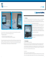
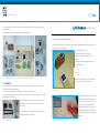
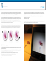
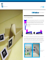
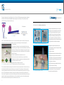
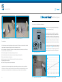
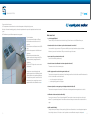
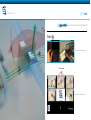
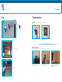
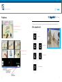
Science Center To Go
| User Manual |
www.sctg.eu
ELLINOGERMANIKI AGOGI
Dr. Angelos Lazoudis
CENTRE FOR EUROPEAN RESEARCH, WALES
Sue Owen
Martin Owen
FRAUNHOFER INSTITUTE OF TECHNOLOGY
Hagen Buchholz
Constantin Brosda
ELLINOGERMANIKI AGOGI
Angelos Theodoropoulos
The Education, Audiovisual and Culture
Executive Agency
With the support of the Lifelong learning
programme of the European Union
| User Manual |
This project has been funded with support from the European Commission.
This publication reflects the views only of the author, and the Commission cannot be
held responsible for any use which may be made of the information contained therein.
| User Manual |
Science Center To Go
Science Center To Go
User Manual for Miniatures
- Table of Contents
1. Introduction
7
2. Equipment and software
9
2.1 The laptop
9
2.2 The miniatures
9
2.3 The webcam
4
10
3. Mini-Fire truck (the Doppler effect)
11
4. Mini-double cone (classical mechanics)
15
5. Mini-wing (wing dynamics)
17
6. Mini-double slit (quantum mechanics)
19
7. Mini-cooler & heater (kinetic theory of gases)
21
8. Frequently asked questions
23
9. Appendix A (SCeTGo visual help and troubleshooting)
25
10. Appendix B (AR markers)
29
5
| User Manual |
Science Center To Go
1. Introduction
Science Center To Go (SCeTGo) is a project that is producing creative, inquiry-based resources for learning science using augmented
reality. The SCeTGo consortium consists of ten research institutions in seven European countries (http://www.sctg.eu). The assembly
and programming is carried out at the Fraunhofer Institute of Applied Information Technology (http://www.fit.fraunhofer.de/index.html).
The first point of contact for any queries users may have is the institution they acquired the suitcase from, which in most cases
will be in their own country.
The Science Center To Go suitcase contains the
resources, which consist of a laptop computer,
a webcam and five small-scale science centre
exhibits (miniatures) (Figure 1):
1. Mini-fire truck (the Doppler effect)
2. Mini-double cone (classical mechanics)
3. Mini-wing (wing dynamics)
4. Mini-double slit (quantum mechanics)
5. Mini cooler & heater (kinetic theory of gases)
Figure 1 The Science Center To Go suitcase and contents (laptop not shown)
The miniatures are set up one at a time in the webcam’s field of view. The webcam creates an image on the laptop screen.
Software adds an overlay to the image. As the miniature is manipulated, the overlay changes in response to the movement. The
overlay depicts an aspect of the scientific phenomenon under investigation, for example trigonometric information or waves
(Figure 2). This process of adding unseen elements to the image on the screen is the augmented reality (AR).
The suitcase is a self-contained science centre that can be used in schools and science clubs or by individuals in their homes.
The aim is to stimulate interest in science and to promote techniques of scientific inquiry, so that subsequent visits to a science
centre are more productive and rewarding. The suitcase can also be used to follow up a visit to a science centre, or as a standalone resource when a visit is not possible.
6
7
| User Manual |
Science Center To Go
2. Equipment and software
2.1 The laptop
The suitcase includes a Dell laptop loaded with Microsoft XP and the AR software for the miniatures. It is also loaded with other
software such as Microsoft Office and Internet browsers. It has a touch screen that can swivel round. When the computer is
switched on the user is presented with a visual menu from which to choose a miniature (Figure 3). Users can return to this menu
after using a miniature by touching the SCeTGo logo in the top right hand corner of the screen.
There is a link to a visual help guide and a video of all the miniatures in use
from the menu screen. The same video is on the SCeTGo website, divided
up into individual miniatures. Links are given in this manual. This is a very
useful starting point for teachers, and a useful troubleshooting resource,
but please note that the miniatures and AR have been updated since this
Figure 2 The AR adds elements to the miniatures
video was recorded. Teachers may not wish their students to watch the video
before they conduct their investigations.
The suitcase is designed to be used by anyone who can manipulate the parts safely. In this manual there are some activities
suggested for use in schools and colleges with the following groups of learners:
•
Younger learners, aged 8 to 13
Users can make screenshots by simultaneously pressing the Fn and Druck
•
Older learners, aged 12 upwards, studying general science subjects
(F11) keys. The images can then be viewed in Microsoft Office, accessible
•
Science specialists, aged 14 upwards, working towards specific science qualifications
from the Start menu.
Figure 3 The SCeTGo menu on the rotatable touch screen
This user manual is intended for teachers rather than learners. The aim of the SCeTGo project is to promote interest in science
and methods of scientific inquiry, so the activity for users could be to work out how to use the miniatures and guess or deduce
2.2 The miniatures
what they are showing, rather than to follow instructions. In all the activities learners have the opportunity to realise that the
The miniatures are small plastic models (Figure 4).
best way to make investigations is to make one change at a time and make careful observations
Each miniature has two or more AR markers (the black and white shapes in Figures 2 & 4) that are recognised by the software
.
through the webcam. The markers disappear from the screen when the AR software detects them (see Figure 2) and in some
cases are replaced by images. The augmented elements are computed according to the position of markers relative to each other,
and to their distance from the webcam. The software responds to the AR marker and not the object itself, so if the marker is not
in the correct position on the miniature the AR will not work correctly.
It is important that:
1. The system is set up on a flat, sturdy surface that does not shake.
2. The level of illumination is good. A brightly lit classroom is usually good enough, but the AR might not work if there is too much light.
3. There is a clear line of sight between the webcam and the markers. The users need to learn to use the miniatures without breaking this.
8
9
| User Manual |
Science Center To Go
3. Mini-fire truck (the Doppler effect)
4. The markers are in perfect condition. For this reason users should avoid touching them. They can be printed out from this
manual (Appendix B).
5. Each miniature is used with the correct software, chosen from the SCeTGo menu.
Online demonstration: http://www.sctg.eu/miniature2.asp
The mini-fire truck exhibit consists of a model fire truck and a strip with an AR marker representing a microphone (Figure 6). The
“microphone” is the lid of the mini-wing box.
There are three elements to the AR:
1. Sound waves coming from the fire truck’s siren
2. the fire truck’s two-tone siren, as detected by the
microphone
3. The frequency of the sent and received frequencies (Hz),
together with the equation
Figure 4 The miniatures: mini-fire truck, mini-double cone, mini-wing, mini-double slit and mini-cooler & heater
where fR is the received frequency, fs is the emitted frequency,
ν is the relative velocity and c is the speed of sound.
2.3 The webcam
The suitcase also includes a USB webcam with a stand. The webcam needs to be assembled, and then positioned so that:
1. The AR markers are detected by the software;
2. The screen shows a good display of the whole miniature (and in some cases, the space around it);
Figure 6 Mini-fire truck
3. It is stable and does not fall over easily. Once a good position has been found it is a good idea to stick the stand to the surface
Sound waves are represented by concentric circles
with adhesive tack or masking tape.
that travel away from the virtual sound source, a
Users can experiment to find the best orientation. In general locating the
two-note siren at the front of the fire truck. The
camera above the miniature, pointing down at an angle, works well (see
Figures 2 & 5).
circles are red at the source and become paler
as they travel away (Figure 7). On the screen the
.
microphone AR marker appears as a microphone
The following sections contain a description of each miniature in turn, with
instructions for setting up and using them
Figure 5 The webcam and stand
10
that detects the sound from its position relative to
the source.
Figure 7 Fire truck as seen on the screen
11
| User Manual |
Science Center To Go
The pitch of the sound is represented by the distance between the circles as they reach the microphone. When the vehicle and
Younger learners who have not yet learned about the wave nature of sound could be asked what they think the circles represent.
observer are stationary the “sound waves” come from the siren in evenly spaced concentric circles (Figure 8), and the pitch of the
Careful experimentation and observation could lead them to make the connection between the pitch of the sound and the spacing
two notes detected by the microphone is constant, with sent and received frequencies of 450 and 590 Hz.
of the circles.
Older learners could be shown a film clip of the Doppler effect, and then asked to use the miniature to explain the effect:
If the fire truck is moved forwards across the frame of the webcam, the circles are closer together in front and further apart
a) when the fire truck is moving, and
behind. The pitch of the sounds is higher as the vehicle moves towards the microphone (Figure 9), and lower as it moves away
b) when the observer is moving.
(Figure 10). The higher the velocity of the fire truck is relative to the microphone, the greater the change in pitch. Thus the
.
frequencies displayed on the screen are correspondingly higher or lower, as appropriate. In figure 7 the fire truck is moving
Science specialists should be able to explain why the perceived frequency of a sound relates to the relative velocity of source and
towards the microphone and the received frequencies are 477 and 625 Hz.
observer. They should be able to explain the equations associated with the phenomenon
The miniature can also be used to show the reciprocal effect, that if the fire truck remains stationary and the microphone is
moved, the pitch of the sound also changes, the relative velocity being the determining factor in the pitches and frequencies
detected. The AR will also respond appropriately when both the sound source and microphone are moved at the same time.
Figure 8 Stationary fire truck
Figure 9 Fire truck moving
towards microphone
Figure 10 Fire truck moving away
from microphone
To use the miniature:
1. Choose the fire truck from the SCeTGo menu
2. Position the webcam so that the fire truck and microphone can be moved about 30 cm and still remain in the camera’s field of
view. Wait until the AR is stable.
3. Move the fire engine and observe the pattern of sound waves, the pitch of the siren (as detected by the microphone) and, if
desired, the frequencies. The AR works best if the fire truck is moved slowly.
4. Move the microphone and note the effect on the pitch of the siren and on the frequencies of the sounds.
5. If desired, turn the sound on and off by simultaneously pressing Fn and Entf on the keyboard.
6. Touch the SCeTGo logo on the screen to return to the main menu.
12
13
| User Manual |
Science Center To Go
4. Mini-double cone (classical mechanics)
Online demonstration: http://www.sctg.eu/miniature5.asp
This is based on a seventeenth century puzzle known as Leybourn’s uphill roller. It consists of two cones joined together
at their bases, on rails that slope and diverge. If the double cone is placed on the narrow, lower end of the track it travels
along the track, appearing to travel uphill (Figures 11 and 12). There is an excellent description of it online from the
University of Cambridge at http://plus.maths.org/issue40/features/uphill/index-gifd.html. together with the history, animations
and associated trigonometry.
Figure 11 Roller viewed from above
Figure 12 Uphill roller viewed from the side, starting and finishing positions
The roller is normally presented as an exhibit whose dimensions are fixed, the objective of which is simply to solve the puzzle. Why does
the roller roll uphill? Why does it appear to break the laws of physics? The answer is of course that it doesn’t. The roller moving up the
divergent tracks is actually falling (grey arrows in Figure 12). The divergence of the rails overbalances their upward slope, allowing the
centre of mass of the cone to drop. This is not obvious unless the exhibit is observed carefully from the side. The SCeTGo miniature consists
of a set of rails whose slope and angle of divergence can be varied, together with three double cones and a cylinder (Figure 13).
Figure 13
Components of the mini-double
cone and the rail setup
14
15
| User Manual |
Science Center To Go
5. Mini-wing (wing dynamics)
The angles of the apices of the 3 cones, 2γ (Figure 14), are 30°, 60° and 90°. The AR measures two variable angles, α, the angle
of inclination of the rails (Figure 15), and β, half the angle of divergence of the rails (Figure 14). The cylinder is present for
comparison purposes, as it always rolls down the slope.
Online demonstration: : http://www.sctg.eu/miniaturel.asp
The AR computes:
The miniature aeroplane wing (mini-wing) consists of an object
shaped like the section of an aeroplane wing, connected to a box
tan (β) x tan (γ)
Figure 14
Angles β and γ
(Figure 17). The angle of the wing with respect to the ground
can be changed. There is also a fan that is powered through a
tan (α)
Figure 15 Angle α
USB connection, and a flat wing for comparison purposes. This
miniature is designed with a specific activity in mind, which is to
help explain why aeroplanes can fly and to determine the angle of
If this is >1 then the double cone rolls up the rails. If it is <1 the cone rolls down. In figure 16 it is balanced. The colours of the
elements of the formula onscreen correspond with the colour of the cone and the angles of the miniature (Figure 16).
To use the miniature:
the wing that maximises the lift afforded to the aeroplane.
Figure 17 Components of the mini-wing miniature and wing set up for use
The AR measures the angle of the wing with respect to the
1. Put the objects on the foam mat, or on another suitable high-friction surface,
and set them up as shown in figures 13 and 16, with the AR marker on the left hand
horizontal and overlays five elements to the image of the wing on
side of the rails. The edges of the rails should butt up evenly against the supports.
the laptop screen (Figure 18):
2. Locate the webcam so that it detects the three AR markers. Choose the double cone
1. The body of the aeroplane.
from the SCeTGo menu.
2. The relative speed and direction of airflow above and below the
3. Choose a cone and indicate on the screen which cone is in use.
wing. Curved green lines represent the direction of airflow. The
4. Put the cone on the rails and see whether it goes up or down the slope.
blue and red arrows on these lines represent the relative speed of
5. Experiment with the miniature, changing angles α and β and observing how the
air above and below the wing. The airflow speed increases as the
cones and the cylinder travel on the rails.
fan is moved nearer to the aeroplane.
6. Observe the effect the changes have on the AR.
3. Uplift. The solid green arrow pointing upwards from the wing
Figure
16 The double cone as it appears on the screen 7. Touch the logo on the screen to return to the main menu.
represents the force acting to lift the wing.
This is a complex model and there are many options for activities in the classroom. Younger learners could look at the one cone
4. Drag. The solid pink arrow represents the force acting against
and the rails without the AR and try to work out why the cone travels up the rails. They could express their findings in words
rather than mathematical formulae. Older learners could discover that if the computed formula is greater than 1 the roller goes
up the rail. They could make and record observations using one of the double cones, predict what the results will be for the
.
the wing’s forward motion. If this is great the plane will stall.
Figure 18 The mini-wing as it appears on the screen
5. Air molecules being sucked through the fan.
others and test their hypotheses. Learners could also be asked to predict how the system would be affected by other changes, for
example if the double cone was partially filled with mercury. Science or mathematics specialists could study the trigonometry,
define the conditions needed to make an uphill roller, and make and test their own
16
17
| User Manual |
Science Center To Go
6. Mini-double slit (quantum mechanics)
To use the miniature:
1. Take the mini-wings out of their box, and then insert the shaped wing into the holes that go through the box. Put the lid on the box
with the AR marker on the left (Figure 17).
2. Plug the fan into a USB port.
3. Choose the mini-wing from the SCeTGo menu.
Online demonstration: http://www.sctg.eu/miniature3.asp
4. Position the webcam so that the wing is in the centre of its field of view and the fan to the left.
5. Check that all the AR markers are detected by the webcam.
This miniature is based on Young’s double slit, which the polymath Thomas Young used in the nineteenth century to demonstrate the wave
6. Adjust the angle of the wing and observe the effect this has on the AR. Allow the AR to stabilise between adjustments.
nature of light. He directed a narrow monochromatic light source at two slits and observed interference patterns on the observation screen.
7. Replace the shaped wing with the flat wing and observe the differences.
Since then experiments have been carried out firing electrons through double slits to define and explore their wave-particle duality.
8. Touch the SCeTGo logo on the screen to return to the main menu.
The aim of the mini-double slit is to use AR to simulate the behaviour of particles
and waves passing through single and double slits.
The main activity with this miniature is to determine the optimum angle of attack for the wing, the one that gives optimal lift, which is of
There is a simple explanation of this topic in animated format at http://www.youtube.
the order of 15° to 20°. Older learners can relate this to Bernoulli’s principle. Science specialists could research other factors that have
com/watch?v=DfPeprQ7oGc
been proposed as contributing to the optimum shape for airfoils and their relative importance.
The miniature (Figure 19) consists of:
Learners can also use this miniature to explore and propose
•
a background box (the same box that is used in the mini-wing miniature);
theories about how wings enable aeroplanes to fly. It may
•
a support for the screens with a track for the slits to move in;
be useful to carry out an experiment from which the pupils
•
two interchangeable screens, with single and double slits;
•
a “cannon” that can be rotated to fire large particles, waves or electrons.
discover that objects are drawn towards faster-moving
.
airstreams. Alternatively they could base theories on the
number of air molecules striking the upper and lower
surfaces of the wing
Figure 19 Miniature with double slit screen in place
There are AR markers on the background box, on each screen and on the cannon. There are three modes of AR:
•
wave mode;
•
particle mode;
•
electron/wave-particle duality mode.
In particle mode a single or double line of particles appears on the background box, representing particles passing through one of the slits
and striking the background. The thickness of the lines builds up with time (Figure 20).
In wave mode the AR shows the effect of waves originating from the cannon The lines on the background of the double slit version
represent vertical extensions of the points where the waves have interfered constructively (Figure 21).
In electron mode electron particles are fired at the slits, and the pattern on the back when there are two slits shows several rows of
18
particles building up, showing that there are interference effects consistent with wavelike properties.
19
| User Manual |
Science Center To Go
7. Mini-cooler & heater (kinetic theory of gases)
Online demonstration: http://www.sctg.eu/miniature4.asp
This miniature consists of a tiny working USB cooler and hotplate
together with a thermometer (Figure 22).
The purpose of the miniature is to visualise how the speed of gas
molecules changes with temperature. There are three AR markers,
one on each element of the miniature. The AR shows representations
Figure 20 Double slits in large particle mode
of molecules moving in the vicinity of the thermometer (figure 23). The
Figure 21 Double slits in wave mode
software detects the proximity of the thermometer to the hotplate or
To use the miniature:
the fridge, and varies the speed of molecule movement accordingly.
1. Set up the miniature as shown in figure 19 using either the single or double slit. The slit that is not in use should be out of the field of
The screen also shows a graph of molecule speed against temperature,
view of the webcam. The background box should be oriented so that the AR marker is to the left.
based on the equation: ν = 20.5 θ+273 where ν is the molecule speed
in m/s and θ is the temperature in °C (Figures 23 and 24). A red line on
the graph corresponds to the temperature on the AR thermometer.
2. Position the webcam to view the miniature. The AR does not extend beyond the boundaries of the miniature, so it can fill the screen.
Choose the mini-double slit from the SCeTGo menu.
Figure 22 Fridge, hotplate and thermometer
3. Choose wave, large particle or electron mode by rotating the top of the cannon.
4. Observe the AR. In particle and electron modes observe the pattern building up on the background box.
5. Observe the effect of moving the slit along the track.
6. Adjust the webcam position to view the AR from different angles. This is particularly useful for the waves.
7. Repeat with different slits and options.
8. Touch the SCeTGo logo on the screen to return to the main menu.
.
Younger learners could use this in wave and particle modes to predict what will appear on the screen and then to use the AR to find
out if they are correct. For science specialists this miniature could serve as an introduction to wave-particle duality. Pupils could try to
explain how electrons travel through the double slit, and deduce whether you can predict where the next electron will appear
20
Figure 23 Screenshot of the mini-cooler & heater
Figure 24 Graph of molecule speed against temperature
21
| User Manual |
Science Center To Go
8. Frequently asked questions
Please note that on the screen:
1. The temperatures are theoretical and are not the actual temperatures of the hotplate, fridge or room.
2. In order to illustrate the underlying principles, the molecule speed observed is many orders of magnitude slower than the actual
speed.
3. The difference in speed at different temperatures is exaggerated.
To use the miniature:
1. Plug the heater and the fridge into USB ports.
2. Push the button on the heater to turn it on if
necessary.
3. Choose the mini-cooler & heater from the SCeTGo
menu.
4. Put the three components in the field of view of
the webcam.
5. Move the thermometer between the two
appliances and observe the changes in the AR. The
AR also works with only one appliance and the
thermometer.
6. Touch the SCeTGo logo on the screen to return to
the main menu.
Younger learners can make observations and
suggest interpretations for the AR. What do the dots
represent? How does their speed change? Why does
it change? Science specialists can relate this to the
kinetic theory of gases, covering the gas constant,
Avogadro’s number and the Boltzmann constant
.
What should I do if:
- Ι can’t find enough USB ports?
There are USB ports at the back and on the side of the laptop. The mini-heater is also a USB hub with four ports.
- the webcam lead is too short to allow me to position the miniature where I want it to be?
You can swivel the laptop screen round. This gives more flexibility in positioning the miniatures, laptop and webcam.
Alternatively, use one of the mini-heater’s USB ports to extend the range of the camera.
- Ι want to turn off the sound on the mini-fire truck?
Press the Fn and Entf keys simultaneously.
- there doesn’t seem to be an AR marker for the microphone (mini-fire truck)?
This marker is also the lid for the mini-wing box.
- the AR is giving unrealistic results (mini-wing, mini-double cone)?
The orientation is important in these miniatures. In the mini-wing box and the rails for the double cone the AR marker must be
to the left. On the double cone check that the rails:
•
rise to the same point on the rail supports;
•
are butted up firmly against the rail supports.
- the waves and particles are not appearing on the background box (mini-double slit)?
The orientation is important in this miniature. The AR marker on the background box (mini-wing box) must be to the left.
- the AR markers have become discoloured/torn/dirty?
You can print out new ones. They are all given in Appendix B. These must have the exact size and position as the original
markers. This is particularly important for the double cone where small changes in orientation affect the calculation of the
angles.
- the AR is unstable/flashing?
.
The light level may not be adequate. You may need a spotlight to increase illumination, or to move the equipment away from
22
direct sunlight to decrease it. If this does not solve the problem one or more AR markers may need to be replaced
23
| User Manual |
Science Center To Go
9. Appendix A (SCeTGo visual help and troubleshooting)
Start
Turn on computer and set up system
Main screen - It is a touch screen
24
25
| User Manual |
Science Center To Go
Stop
Troubleshooting
good
Good light conditions and well illuminated AR markers
Click or tap to stop exhibit
Steep camera angle
Put things back into place
not so good
Shadow edges on markers
Turn off computer
26
Good light conditions
Bad light conditions and poorly illuminated AR markers
Occlusion of markers
Markers are not fully visible in the
camera image
27
| User Manual |
Science Center To Go
10. Appendix B (AR markers)
Problems
The AR may not work well if the markers are not in perfect condition. If they become damaged you can reprint and replace them.
Mini-double slit
The touch screen does not work
If the touch screen does not react on
tapping try swiping
01 / Box
08 / Single Slit
How do I update the system?
Follow instructions below
09 / Double Slit
15 / Cannon Control
28
29
| User Manual |
Science Center To Go
Mini-Fire truck
Mini-cooler & heater
The microphone AR marker is the box of the mini-wing and
mini-double slit
00 / Fire Truck
14 / Thermometer
Mini-double cone
06 / Ramp B
05 / Ramp A
04 / Base
12 / Heater
30
13 / Cooler
31
| User Manual |
Science Center To Go
Mini-wing
00 / Wing
01 / Box
16 / Flat Wing
11 / Fan
32
33
Science Center To Go
34
| User Manual |
35
www.sctg.eu