1
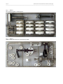
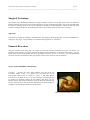
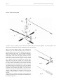
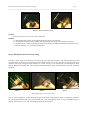
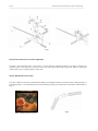
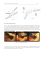
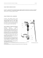
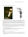
MEDIN KNEE JOINT
MEDIN UNIVERSAL MU
SURGICAL TECHNIQUE
Doc. MUDr. Pavel Vavrík, CSc.
Page 2
MEDIN KNEE JOINT IMPLANT SURGICAL TECHNIQE
_________________________________________________________________________________________________________
Introduction
MEDIN generation II knee joint implant design is based on 15 year experience with previous model and up to date
knowledge in the knee implants field.
This new prosthesis system enables easy and perfect fixation of implant with minimal bone resection. The
instrument set is optimised to have minimal weight and long durability. Instrument set is universal and can also be
used for implantation of previous generation of WALTER knee implant and also for revision implant and noncemented implant.
The instrument set is designed to allow step by step solution of all the usual problems even by not very
experienced surgeon. On the other hand the experienced surgeon can feel free to modify the surgical technique to
infrequent situations.
This publication is intended to be an instrument set user’s manual. It is limited only to basic operation technique
and it is supposed that the surgeon and the other staff are perfectly familiar with general rules of knee implant
surgical techniques.
The goal of the publication is to enable quick orientation and correct use of individual instrument set elements to
reach the most optimal results possible and to avoid unnecessary damage on instrument set or implants. By far this
is not intended to be a surgical technique textbook.
Instrument set
The instrument set is accommodated in 4 metal holders permitting clear arrangement of tools during procedure,
their transportation sterilisation and storing. Holders layout is shown in following sketches (Fig. 1 - 4)
MEDIN KNEE JOINT IMPLANT SURGICAL TECHNIQE
Page 3
_________________________________________________________________________________________________________
Fig. 1 Holder 1
Femoral and universal tools I. Instruments for femoral centration, distal femoral resection and auxiliary tools necessary
for all the operation duration.
Fig. 2 Holder 2
Femoral tools, part II. Set of tools and templates necessary for finishing of femoral resection in accordance with the size
of femoral component.
Page 4
MEDIN KNEE JOINT IMPLANT SURGICAL TECHNIQE
_________________________________________________________________________________________________________
Fig. 3 Holder 3
Set of implant templates and the impactor
Fig. 4 Holder 4
Tibial resection instruments. Set of instruments for tibial .
MEDIN KNEE JOINT IMPLANT SURGICAL TECHNIQE
Page 5
_________________________________________________________________________________________________________
Surgical Technique
The standard and recommended technique starting by femoral resection is described. All the tools are marked by
Roman numerals showing the order of their application in case of standard procedure. The Arabic numerals after
the slash are showing the given size of the component. Modularity of instrumentation enables to start with tibial
resection if surgeon decides so. Individual partial steps in given phase of the procedure do not change.
Approach
Instrument set permits this implant to be implanted in any standard operating approach, so it does not demand any
changes in your usage. The procedure is not influenced by application of tourniquet.
Femoral Resection
After the exposure of the knee joint, the release of soft tissue and the setting the knee joint into flexion it is
suitable but not necessary to remove marginal osteophytes which facilitates to determine more exactly the size,
lateral shift of femoral component and tonus of colateral structures. In case of necessity the first approximate
correction of soft tissue balance by their appropriate release on the concavity of axial deformity.
Step 1: Femoral medullar canal opening
Procedure: Introduce the thin 8mm diameter stop drill from the
instrument holder 1 (Fig. 1) in femoral axis just before the top of
intercondylar notch in the very center or - better - 5 mm more medial.
Drill down to the depth of 4 to 5 cm. The preparation of opening should
be finished by unforced pushing the non-rotating drill down into the
femoral canal in full length of the drill. The drill will settle automatically
into the canal direction. This procedure should decrease the possibility of
perforation of the femoral compacta by the drill peak.
Photo 1 Femoral medullar canal opening
Page 6
MEDIN KNEE JOINT IMPLANT SURGICAL TECHNIQE
_________________________________________________________________________________________________________
Step 2: Femoral centration
Fig. 5
Procedure: (Fig. 5) Centering device should be assembled first. Put the parts together. All the descriptions and
marks engraved should be correctly readable from the view of surgeon.
Sleeve the basic femoral block on the guiding bar
(marked by I). The handle of guiding bar (2) must be in
vertical position not to cover the fixation pin holes (3).
Mount selected angle insert (4) with selected valgozity
setting (5,7,9 deg) from the set for the right or left knee
from upside. Then insert the upper structure (II) into
upper holes (5) of the basic block. The arrows on the
front side of the block and on the upper structure should
be in opposite. Finish the assembly by inserting (topdown) the ruler (III) into vertical slit (6) of the upper
structure (II). Insert the centering bar (7) into the hole in
the ruler. Mount the handles (8) if necessary. Introduce
the guiding bar of the assembled device (Fig. 7) into the
pre-bored opening in the femur. Pins can be introduced
directly or by means of special holder (Fig. 6a) which is
included in the instrument set holder 1. Set the correct
rotation by turning the template around the bar. Fix the
position of the template by driving the shorter pins of
template fixating needles at least into one femoral
condyle.
In this stage it is suitable to check the correct position of
template by centering wire, the peak of it should aim into
the center of hip joint.
Fig. 6
Fig. 6a
MEDIN KNEE JOINT IMPLANT SURGICAL TECHNIQE
Page 7
_________________________________________________________________________________________________________
Photos 2 and 3: Femoral centering
Problem:
Centering wire does not aim to the center of hip joint
Solution :
1. Check guiding bar position in the femoral canal and correct it if necessary.
2. Check the correct setting of the angular (left, right) gauge and change it for another if necessary.
3. Check the correct rotation of setting and repair it by rotating of template around the longitudinal axis of
femur if necessary (i.e., around the guiding bar).
Step 3: Distal femoral resection level setting
Procedure: After removing of centering bar remove the ruler (III) and introduce it into the horizontal upper slot
(6) of the upper structure (II). Set the distal femoral resection block (IV) on the ruler. Set the optimal level of the
resection by moving it along the scale (usually 8 or 10 mm, see Fig. 7). Fix the block by 2 pins through the holes
marked. Remove the guiding bar, ruler and all the femoral template. Press the fixed block to the front of femoral
compacta.
Photo 4
Photo 5
Photo 6
Distal femoral resection level setting
Note: It is more suitable to pre-drill the holes for pins by drill of 2.8 mm diameter which is included in instrument
set. The simple hammering the pins is also possible, but it can cause slipping of the pin tip, or deformation and so
shift the resection level, or it cause the change of template axial position.
Page 8
MEDIN KNEE JOINT IMPLANT SURGICAL TECHNIQE
_________________________________________________________________________________________________________
Fig. 7
Step 3a: Resection level correction (optional).
Procedure: If the resection level is not correct, it can be raised or reduced by about 2 or 4 mm by removing of
resection block. Leave the pins in the bone in this case and slip the block back using holes -2mm or +2mm and
+4mm relative to the original position on the ruler.
Step 4: Distal femoral resection
Procedure: Make the resection by attached saw blade just along distal surface of resection block. Guide gib (Fig. 8)
included in holder 1 can be attached to the resection block by fitting it into the holes on the border of the block (9)
(Fig. 7).
Photo 7 Distal femoral correction
Fig. 8
MEDIN KNEE JOINT IMPLANT SURGICAL TECHNIQE
Page 9
_________________________________________________________________________________________________________
Step 5: Femoral component size measurement and making guiding holes
Fig. 9
Photo 8: Making guiding holes
Fig. 10
Procedure: Use femoral aimer (V) (Fig. 9), with handles attached if
necessary. Attach the aimer on distal resected surface of femur so that
the lower heels of aimer (11) fit behind the dorsal part of condyls and
lock it in the appropriate position by 2 pins. Sleeve the indicator (VI)
(Fig. 10), correct its position by the adjusting screw (12) so that the tip
touched the ventral femoral compacta. Read the size of femoral
component on the vertical scale of the pointer.
Remove the pointer and use one of the drilling templates (VII)
according to the selected femoral component size, so the fixing pins of
the aimer go through the hole (15) next to center the drilling template.
Add the vertical handle (8) to the template. Now you can correct the
rotation around the vertical axis by up to 3 deg. (right-and-left ) by
turning of the template around the centering pin (16). If the rotation is
set, lock the template by pins (3). At the end pre-bore both guiding
holes for further instruments and femoral component by stop drill
included in holder 1.
Rotation correction
Fig. 11
Fig. 12
Page 10
MEDIN KNEE JOINT IMPLANT SURGICAL TECHNIQE
_________________________________________________________________________________________________________
Problem:
The scale shows the intermediate size
Solution:
1. Check if the aimer (V) touches perfectly the distal resection surface. Correct the position if necessary.
2. Check if the tip of the pointer really touches ventral femoral diaphysis compacta and not the ostephyte or
even the soft tissue.
3. If the problem outlasts, selection of larger size is always more advisable.
Note: For easy and quick removing of pins from the hard bone
during the procedure use the pin extractor (10) (Fig 13) which is
accommodated in the instrument set holder 1. It is not necessary
to open the extractor. It is sufficient to sleeve the extractor on the
end of the pin and clasp.
Fig. 13
Step 6: Ventral and dorsal femoral resection
Procedure: After removing of femoral aimer insert the plugs (19) of rectangular resection block (VIII) of
appropriate size (measured in the previous step) into the prepared holes (Fig. 14). Settle the block carefully by
impactor taps to fit perfectly on the distal resection surface. Be sure the legend engraved on the block are readable
correctly and all the arrows are aiming up. Add holders (8) if needed and attach the saw blade guide gib. Make the
dorsal resection of femur along the appropriate block surfaces.
Photos 9, 10, 11: Ventral and dorsal femoral resection
Note: When setting the resection block check if the „SUPERIOR“ legend
engraved on the femoral surface of block is not upside down and the
arrows are aiming up to the ventral compacta. The other position of the
block can cause shift of the resection level in ventrodorsal direction.
Fig. 14
MEDIN KNEE JOINT IMPLANT SURGICAL TECHNIQE
Page 11
_________________________________________________________________________________________________________
Fig. 16
Fig. 15
Step 7: Skew femoral resections
Procedure: After removing of rectangular resection block use triangular femoral resection block (IX) of the same
size, set it carefully into guiding holes by means of 2 pins (Fig. 17) so that the “SUPERIOR“ is upside up. Make
the resection of ventrodistal and dorzodistal skewed surface of femur along the surfaces marked by arrows first.
Add the guide gib (Fig. 18) if desired. Mark medial resection of ventrodistal surface by saw into depth of about 3
mm along the slot. Finish the resection by a sharp chisel 20 mm width (not included in instrument set and should
be prepared before the procedure ).
Photos 12, 13, 14: Skew femoral resections
Note: Check if the block is in the position that the slot is on the upper side and “SUPERIOR“ engraved on surface
is upside up. Skewed surfaces are not fully symmetrical for every individual size and the incorrect position of block
can cause principal and hardly correctable error of resection.
Page 12
MEDIN KNEE JOINT IMPLANT SURGICAL TECHNIQE
_________________________________________________________________________________________________________
Ventrodistal
resection surface
Central resection
Width 20 mm
Depth: 3 mm
Dorsodistal
resection surface
Fig. 17
Obr. 18
Step 8: Intercondylar resection
Procedure: Use the template for intercondylar resection (X) from the instrument set holder 2 (Fig. 19) in
accordance with the selected size of femoral component. Set the pins (19) of the template into guiding holes on the
distal resection surface of femur. Press the template carefully to stabilize its position and mark the intercondylic
resection along the inner surfaces of the slot of template to the depth of 5mm using oscillating saw. Finish the
resection in ventrodorsal direction using suitable chisel.
Intercolic
resection
Fig. 19
Photo 15, 16: Intercondylic resection
MEDIN KNEE JOINT IMPLANT SURGICAL TECHNIQE
Page 13
_________________________________________________________________________________________________________
Step 9: Check of femoral resection
Procedure: Test the resection by careful setting of test femoral template of appropriate size which is included in
holder 3 of instrument set. Testing femoral template differs from the service one by non polished articulating
surface for not to interchange them by mistake.
Step 10 Tibial resection - preparation
Procedure: After sufficient release of soft
tissue and shift of tibia forward in flexed knee
using elevatorium attach the tibial gauge
assembled before (Fig. 20) (set during
primoimplantation under standard conditions,
the arrows (1) on the vertical guiding bar and
lower leg of gauge should aim opposing).
Note: correction of setting into valgozity or
varozity should be used only in special
anatomical
conditions
congenital
abnormality, posttraumatical status or
revision operations). Set the necessary dorsal
inclination by sliding of talocrural sleeve (3)
along the guiding bar (2). Fix the position by
the fixing screw (4). Set the approximate
length of device using the central nut (5). Fix
the gauge prepared this way using hock sleeve
(3) around the talocrural joint. Drive the
longer pin (6) into the area of lateral tubercle
of intercondylical eminence.
Set the correct rotation let the shorter axis of
the resection block (7) (according to the type
of axial deformity) passes through the center
of tibial tuberozity or slightly out of it and
through the medial border of lateral tubercle
of intercondylical eminence.
Fig. 20
The guiding bar (2) of talocrural sleeve (3)
should aim to the first intermetatarsal space of the foot which must be in ortograde position in talocrural joint and
sub-talar joints.
Fix the tibial gauge in this setting by driving the shorter pin (8) into tibial plate.
Page 14
MEDIN KNEE JOINT IMPLANT SURGICAL TECHNIQE
_________________________________________________________________________________________________________
Step 11 Setting of the height of tibial resection (Fig. 21)
Photo 17: Setting of the height of tibial resection
Fig. 21
Set the tip of the pointer (9) over the deepest place of supposed tibial resection and tighten slightly the fixing screw
(10) of pointer. Then release the support nut of resection block (11) and let it completely down. The released
resection block should slip distally as far as the tip of pointer touches the tibial surface. Fix the set level of tibial
resection surface by preboring by 3.2 mm drill and by setting the pins into the stepped holes of the block.
Release completely the fixing screw (10) of the pointer, remove them and put them out. Remove the tibial gauge
upside by means of puller included in the tibial instruments holder. To remove the tibial gauge place the upper
edge of the tibial gauge into clamping jaws of puller and tap the gauge up. Put the gauge out after releasing the
talocrural sleeve (3).
There is only fixed resection block on tibia now on which the saw sheet guide gib can be added. The holes in
resection block which enable shift by 2-3 mm relative to the original level can be used for additional corrections if
necessary. Axial position of the resection block can be checked by ruler (13) the pins of which should be fixed into
the holes on the upper surface of the resection block. Attach the centering bar (14) (Fig. 20). If the block is
correctly set, the tip of the bar should aim into the center of the talocrural joint.
Note: After the fixing of gauge before the resection:
1. Check if the long axis of tibial gauge aims from the center of the knee into the center of the talocrural joint.
2. Check the correct dorsal inclination setting of the resection block by using the lateral view.
3. Check if the rotation is correct.
4. Check the resection level which should not exceed 10 mm on the lateral condyle
Problem
Incorrect rotation, incorrect dorsal inclination or wrong axis.
Solution:
In these cases it is absolutely necessary to extract all the fixation pins and repeat all the gauge setting process.
Any attempt to correct the position of fixed resection block e.g. by its shift along the guiding bar or by the
change of the sleeve rotation, would change the position only for the price of deformation of pins or their
loosening in the bone.
MEDIN KNEE JOINT IMPLANT SURGICAL TECHNIQE
Page 15
_________________________________________________________________________________________________________
Problem:
Unsatisfactory resection level.
Solution:
Unsatisfactory resection level can be corrected to some extend by shifting the resection block by 2-4 mm in
proximal or distal direction. In these cases keep the pins in the block in situ and use appropriate holes in block.
Remove completely the tibial gauge.
Step 12 - Finishing the tibial fitting
Finish the tibial surface fitting by punching the stem hole by means of classical MEDIN punch. Make sure that the
full surface of punch touches the bone and that the rotation is correct.
Prepared under supervision of the 1st Orthopaedical Clinics of Medical Faculty of Charles University in Prague
for MEDIN Orthopaedics, a.s.
© MEDIN Orthopaedics, a.s., 2006