1
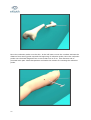
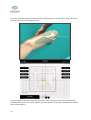
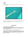
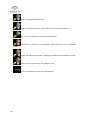
Ekliptik d.o.o. Teslova 30 1000 Ljubljana Slovenia T: +386 1 477 66 31 F: +386 1 477 66 32 W: www.ekliptik.si USER MANUAL GUIDING STAR /TOCOS 1 Contents GUIDING STAR...................................................................................................... 4 TOCOS Module ...................................................................................................... 6 Before you start .................................................................................................... 6 Start with the surgical procedure ............................................................................10 Sterilization .........................................................................................................14 Instructions for sterilization ................................................................................14 GUIDING STAR ..............................................................................................15 TOCOS module...............................................................................................15 Warnings .............................................................................................................15 Technical data ......................................................................................................17 CERTIFICATE OF CONFORMITY ...............................................................................19 2 Picture 1: GUIDING STAR Parts 3 GUIDING STAR Parts description: 4 • Computer unit with integrated display and touch screen (1.) • Navigational unit (2.) • Power supply unit (3.) • Cart with wheels (4.) • Extension arm (5.) • Transmitter (6.) • Power cable (7.) • Computer button on/off (8.) • Navigational unit power and USB connection (9.) • Navigational unit 4 socket (10.) • Transmitter cable connected to the navigational unit (11.) • Power unit on/off button (12.) • Wheel with brake (13.) • Computer unit power and USB connection (14.) Picture 2: TOCOS module parts 5 TOCOS Module Parts description: • Aiming probe (31.) • Aiming probe connector (31.a) • Plastic tube (32.) • Reduction probe (33.) • Sensor for reduction probe (34.) • Sensor connector (34.a) • Preamplifier cable (35.) • Preamplifier connector (35.a) • Preamplifier socket (35.b) Before you start The TOCOS module has to be sterilized. Don't sterilize with autoclava! Use cold sterilization (plasma, Eto). The navigational unit and the computer unit must be switched off. 6 The Guiding Star/TOCOS has to be placed on the proper position for the surgical procedure and connected to the power. Switch on the power unit with the button located on the front panel. Switch on the navigational unit with the button located on the back of the navigational unit. Press the power button on the front of the computer to switches on the computer. 7 On the computer screen the »Welcome« mode appears. Connect two preamplifiers to any of the 4 sockets on the front of the navigational unit. Push the preamplifiers' connectors into the sockets on the front of the navigation unit until they click. Gently insert the each probe's connector (reduction probe and aiming probe) into the preamplifier's socket until it touches the bottom of the socket. Gently rotate the probe's connector until you can push it further into the socket. Push the probe's connector to the end of the socket until it clicks. 8 Do not touch the screen again until the GuidingStar/TOCOS enters into the »ACTIVE« mode. When the probes are connected and the GuidingStar/TOCOS is »ACTIVE« press the button GuidingStar/TOCOS to go into the TOCOS program. Module TOCOS don’t have to be calibrated. Before you start to use TOCOS probes you have to choose the predefine bone diameter on the left and right side of the computer monitor. 9 Start with the surgical procedure Insert the aiming probe into the plastic tube. Once the entering point in the bone is defined insert the aiming probe with plastic tube into the medullar channel. Push the aiming probe forward along the medullar channel until you reach the fracture edge. 10 Move the reduction probe over the skin. In the left lower corner the numbers indicate the distance from aiming probe cap and the beginning of reduction probe. Move the reduction probe over the distal fragment but no more than 3cm to 5 cm from fracture end of proximal bone part. Mark that position and make the incision for inserting the reduction probe. 11 Push the reduction probe towards the bone and press it on to the bone. With free hand push the bone from the opposite site. On the computer monitor check the position of the reduction probe (the squares with perpendicular green lines) with regard to aiming probe (small green squares surrounded with yellow square). 12 Move the reduction probe to overlap the squares on the computer monitor. 13 When the squares are overlap push the aiming probe forward into the medullar channel of the distal fragment. After you done the reduction pull out the aiming probe from the plastic tube. Insert the guiding wire into the plastic tube and continue with standard surgical procedure for inserting the intramedullary nail. Sterilization Instructions for sterilization All the probes and preamplifier have to be sterilized with plasma before they can be used in the operating room. Other accessories can be sterilized using other sterilization method. Do not use autoclave sterilization for probes and preamplifiers! Always sterilize more probes, tools and preamplifiers than needed directly: this will allow the surgeon to carry on using the system in the event that one of the sterilized accessories comes in contact with a non sterile object or person or reaches its usage limit. 14 GUIDING STAR Prior to the operation, cover the cart (including the computer unit, the navigational system, the extension arm and the power supply unit) with a set of sterile sheets for x-ray machines, min. size 225 x 90 cm. If the sterile sheets are too short, you can cover the navigational unit separately with an adhesive waterproof sterile compress. TOCOS module If the TOCOS module is to used, then the following TOCOS parts have to be sterilized with plasma before use in the operating theater: • 2 reduction probes (1 as a spare), • 2 aiming probes (1 as a spare), • 3 Preamplifiers (1 as a spare). Place all the accessories that have to be sterilized in appropriate box. Pay special attention to the reduction and aiming probes cables and connectors they have to be rolled into a coil when sterilizing. The aiming probe must be completely stretched out. Place all the accessories in a plasma chamber and start the sterilization cycle. After the sterilization update your documents with the number of times each probe has been used; each probe can be used for a maximum of 15 surgical operations. Warnings • • 15 There are some problems with the navigation system. Is it connected properly and switched on? The system is warming up. Please wait! • Keep the calibration stand still! • Keep the probes between 13cm and 40cm from the transmitter! • One or more probes are not connected properly. • Information in probe %d is corrupted. Report this error to the hardware vendor. • Probe %d usage has expired. Return the probe to the hardware vendor. • Probe in port %d has only %d usage(s) left. • There is interference from the environment. 16 Technical data Storage and Operating Specifications • Storage conditions: 0°C to 60°C with 20% to 90% humidity, non-condensing • Operating conditions: 15°C to 35°C. Computer unit • Power supply: 100-240V 47-63Hz. 80W • Display: 17'' colour active matrix LCD, 5 wire resistive touch screen • Resolution: 1280 x 1024 pixels • Processor: Intel® Mobile Pentium M™ (1.6GHz) with 1 MB (2nd level) cache memory • Hard disk drive: 20GB • System memory: 512MB DDR RAM • Audio: Internal speaker, amplified mono, 8 ohm, Speaker Out (1/8" mini-phone), Linein and Microphone-in (1/8” mini phone) • Ports: 2 USB, Type A receptacles, USB 2.0 compliant 1 DVI-I digital/analog video output 1 Serial, RS-232, 9-pin micro-miniature-D LAN 10/100 BaseT Ethernet, RJ-45 1 Compact Flash memory socket, Type I 1 PCMCIA/CardBus Slot, Type I or Type II • Warranty: one year limited warranty Power supply unit • Power: 100-240V, 50/60Hz 100Wmax • Fuses: F1-F4, T4.0AL 250V • Operating temperature: 15°C to 35°C Navigational unit • Power supply: from 85 to 265V, 47-63Hz. 60 VA • Fuses: A fuse drawer is located on the rear panel, next to the AC power inlet. Both power entry conductors are protected by size 5 x 20 mm fuses: 1 .0 A ; 250V; T (Time Lag /SLO-BLO) • Operating temperature: 15°C to 35°C • Warm up: System meets accuracy specifications after 5 mins. 17 Transmitter • 3.75” (9.6cm) cube with 10’ (3.05m) cable Sensors • Sensor max OD 1.3mm • Sensor max length 6.7mm • Cable max OD 0.6mm • Cable length: 2.5 meters • USP class 6 epoxy sensor housing • USP 6 polyester protective wrap (bare sensor only) • Maximum temperature of exposure 150 degrees C • Sensor assembly and cable materials are plasma, EtO, gamma and cold sterilant tolerant. • Semiconductor devices in the connector are not gamma shielded and may be damaged or erased if exposed to gamma radiation. • Connectors are not sealed and must not be subjected to immersion in liquids of any type • Do not subject cable to an axial pull greater than 200 grams. • Additional materials for vinyl sensor assemblies: Tygon tubing USP 6, USP class 6 epoxy tip PVC shrink tubing on cable at connector end • Connector housing is PEEK material • Static accuracy: 1.4mm RMS position, 0.5 degree RMS orientation • Translation range: 20 cm minimum to 71 cm maximum in X, +/- 30 cm in Y and Z in the forward (positive X) hemisphere only. • Update rate: 7.1 to 90 measurements per second. Default measurement rate = 68.3 Hz, The system is calibrated at 68.3 Hz. Preamplifiers • Module max OD (minus threaded cap): 23.5mm • Module max length (including sensor connector) 163mm 18 • Module length (excluding sensor connector) 144mm • Cable max OD 5mm • Cable length 3 meters NOTE: Current pre-amplifiers are designed with consumer grade materials and construction. Specifically, they are designed to be resistant only to plasma sterilization method. Immersion in liquids will render them inoperable. Software • Operating system: Windows XP SP2 • Application: LIDIS/TOCOS/BATTIATO software version 1.1.1.1. or newer • Security: LIDIS/TOCOS/BATTIATO runs in a limited account. CERTIFICATE OF CONFORMITY No. CE 223-0009/07_3 The product complies with the essential requiments of the following directives: 93/42/EEC – Medical Device Directive (MDD) – Annex IV Classification of the device: Class IIb (Active surgically invasive device for transient use) Verification Report No.: T223-VER-014/07 19