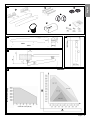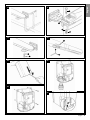
1
MhouseKit WG20S
For power-operated swing gate
Installation instructions and warnings, and User Manual
IS0010A00EN_28-03-2011
GENERAL SAFETY WARNINGS AND PRECAUTIONS
MAINTENANCE
STEP 1
2
KNOWLEDGE OF THE PRODUCT AND PREPARATION FOR
INSTALLATION
STEP 9
15
PRODUCT DISPOSAL
15
STEP 2
2
FURTHER INFORMATION
2.1 - PRODUCT DESCRIPTION AND INTENDED USE
2
STEP 10
16
2.2 - COMPONENTS USED TO SET UP A COMPLETE SYSTEM
3
10.1 - ADVANCED SETTINGS
16
10.2 - OPTIONAL ACCESSORIES
17
PRELIMINARY CHECKS FOR INSTALLATION
STEP 3
3
3.1 - CHECKING SUITABILITY OF GATE TO BE AUTOMATED AND
RELATIVE ENVIRONMENT
3
3.2 - PRODUCT APPLICATION LIMITS
3
3.3 - PRODUCT DURABILITY
3
STEP 4
4
4.1 - PRELIMINARY CHECKS FOR INSTALLATION
4
4.2 - PREPARING ELECTRIC CABLES
4
10.3 - ADDING OR REMOVING DEVICES
19
10.4 - MEMORIZING ALL RADIO TRANSMITTERS
20
10.5 - TROUBLESHOOTING
22
10.6 - DIAGNOSTICS AND SIGNALS
22
TECHNICAL SPECIFICATIONS OF PRODUCT
COMPONENTS
25
APPENDIX 1 - EC declaration of conformity
28
USER’S GUIDE
INSTALLATION: ASSEMBLY AND CONNECTION
OF COMPONENTS
STEP 11
29
STEP 5
6
11.1 - SAFETY INSTRUCTIONS
29
5.1 - INSTALLING THE GEARMOTOR WG10SK
6
11.2 - GATE CONTROL
29
11.3 - MANUALLY RELEASING OR LOCKING THE GEARMOTOR
29
STEP 6
6
11.4 - MAINTENANCE OPERATIONS ADMISSIBLE TO THE USER
30
6.1 - INSTALLING CL20S
6
11.5 - REMOTE CONTROL BATTERY REPLACEMENT
30
6.2 - INSTALLING AND CONNECTING PHOTOCELLS PH100
7
11.6 - REMOTE CONTROL BATTERY REPLACEMENT
30
APPENDIX 2 - EC declaration of conformity
31
6.3 - INSTALLING AND CONNECTING THE FLASHING LIGHT FL100
7
6.4 - ELECTRICAL CONNECTION TO CONTROL UNIT CL20S
7
PROGRAMMING
STEP 7
13
7.1 - POWER SUPPLY CONNECTION
13
7.2 - INITIAL CHECKS
13
7.3 - LEARNING CONNECTED DEVICES
13
7.4 - LEARNING THE GATE LEAF OPENING AND CLOSING ANGLES
13
7.5 - CHECKING THE RADIO TRANSMITTERS
13
7.6 - SETTING
13
TESTING AND COMMISSIONING
STEP 8
15
8.1 - TESTING
15
8.2 - COMMISSIONING
15
English – 1
English
CONTENTS
English
GENERAL SAFETY WARNINGS AND PRECAUTIONS
––– STEP 1 –––
Safety warnings
• CAUTION! – This manual contains important instructions and
warnings for personal safety. Incorrect installation could cause serious physical injury. Carefully read all parts of this manual before starting
any work. If in doubt, suspend installation immediately and contact the
Mhouse Technical Assistance.
• CAUTION! – Important instructions: keep this manual in a safe
place to enable future product maintenance and disposal procedures.
• CAUTION! – According to the most recent European legislation,
the production of a power-operated door or gate must comply with
the standards envisaged in the Directive 2006/42/EC (Machinery
Directive) and in particular standards EN 12445; EN 12453; EN
12635 and EN 13241-1, which enable declaration of presumed
conformity of the automation. In consideration of this, all mains
connection, testing, commissioning and maintenance operations
must be performed exclusively by a qualified and skilled technician.
All preliminary set-up, installation and programming operations
may be performed by personnel with standard skills, provided that
all instructions and the relative sequences in this manual are strictly observed, with particular reference to the warnings in this STEP
1.
Installation warnings
While reading this manual, take care to observe all instructions
marked with the following symbol:
These symbols indicate subjects that may be the source of potential
hazards and therefore the prescribed operations must be performed
exclusively by qualified and skilled personnel, in observance of
these instructions current safety standards.
• Before installation, ensure that this product is suitable for automation of
your gate or door (see STEP 3 and chapter “Product Technical Specifications”). If not suitable, do NOT proceed with installation.
• On the system power mains install a device for disconnection (not supplied), to guarantee a gap between contacts and complete disconnection in the conditions of overvoltage category III.
• All installation and maintenance operations must be performed
with the automation disconnected from the power supply. If the
power disconnect device is not visible from the location of the automation, before work a notice should be affixed on the disconnect device,
with the text “CAUTION! MAINTENANCE IN PROGRESS”.
• CAUTION! - Never power up the motor before fully installed
on the column and leaf of the gate.
• During installation, handle the automation with care, avoiding the risk of
impact, dropping or contact with any type of liquid. Never place the
product near to sources of heat and never expose to naked flames. This
may damage product components and cause malfunctions, fire or hazardous situations. If this occurs, suspend installation immediately and
contact the MhouseTechnical Assistance.
• Never make modifications to any part of the product. Operations other
than as specified can only cause malfunctions. The manufacturer
declines all liability for damage caused by makeshift modifications to the
product.
• If the power cable is damaged, it must be replaced exclusively by a
qualified technician, to avoid potential risks.
• Connect the control unit to an electric power line equipped with an
earthing system.
• This product is not designed to be used by persons (including children)
whose physical, sensorial or mental capacities are reduced, or with lack
of experience or skill, unless suitable instructions regarding use of the
product have been provided by a person responsible for safety.
• The key-operated selector switch must be positioned in sight of the
automation, but far from moving parts and at a height of at least 1.5 m
from the ground, not accessible by the public. If this is used in “hold-torun” mode, ensure that there are no persons in the vicinity of the
automation.
• In the vicinity of the automation children must be supervised to ensure
that they do not play with it.
• Ensure that there are not points of entrapment or crushing with fixed
parts when the gate leaf is in the maximum opening or closing position;
protect parts if necessary.
• The product may not be considered an efficient system of protection
against intrusion. If an efficient protection system is required, the
automation must be integrated with other safety devices.
• The automation must not be used before performing the commissioning
procedure as specified in the chapter “Testing and commissioning”.
• Check the automation frequently to ensure there is no imbalance, signs
of wear or damage to electrical or mechanical parts. Do not use the
automation if adjustments or repairs are necessary.
• In the event of long periods of disuse, to avoid the risk of leaks of harmful substances from the optional battery (PR1) disconnect it from the
automation and store in a dry location.
• Do not allow children to play with fixed control devices. Keep remote
control devices out of reach of children.
• The product’s packaging materials must be disposed of in full compliance with local regulations.
Operation warnings
• For cleaning the product surfaces, use a soft damp cloth. Use water
only; never use detergents or solvents for cleaning.
KNOWLEDGE OF THE PRODUCT AND PREPARATION FOR INSTALLATION
NOTES TO MANUAL
• This manual describes how to set up a complete and optimal
automation, such as that shown in fig. 6, using all Mhouse devices
that are part of the automation system named “WG20S”. Some of
these devices are optional and may not be present in the kit. For a
complete overview of the devices, refer to the MHouse product
catalogue.
• This manual has been drawn up as a step-by-step guide. Therefore, to ensure safe and facilitated assembly and programming
procedures, perform all operations described in the same order as
specified in this document.
2 – English
––– STEP 2 –––
2.1 - PRODUCT DESCRIPTION AND INTENDED USE
The devices in this kit, plus other accessories (some optional and not
included in the pack), form the automation system named “WG20S”,
designed for the automation of a “residential” swing gate. Any other use
than as specified herein or in environmental conditions other than as
stated in this manual is to be considered improper and is strictly prohibited!
The main part of the automation comprises one control unit and two
electromechanical gearmotors, each equipped with a 24 V DC motor, a
worm reducer and a mechanical locking system with key to enable manual opening and closing of the gate in the event of a power failure.
The control unit comprises a board and incorporated radio receiver which
receives the commands sent by the user via a transmitter. It can memorise up to 256 GTX4 transmitters (if memorised in “Mode I”) and up to 6
pairs of PH100 photocells.
2.2 - COMPONENTS USED TO SET UP A COMPLETE
SYSTEM
Fig. 1 illustrates all components used to set up a complete system, such
as that shown in fig. 6.
Components shown in Fig. 1:
A - 2 electromechanical gearmotors WG10SK with fixing brackets
B - 3 release keys
C - 1 pair of PH100 photocells (one TX and one RX)
D - 2 GTX4 radio transmitters
E - 1 FL100 flashing light with integrated aerial
F - 1 control unit CL20S
G - Metal hardware
Notes:
- Some devices and accessories specified in the manual are optional and
may not be present in the kit. .For a complete description, refer to the
Mhouse product catalogue or visit the website
- The limit switch stops are not supplied in the pack and are not part of the
Mhouse product range.
The shape of the gate and weather conditions (such as the presence of
strong winds) may reduce these maximum values; in this case the user
must measure the torque required to move the leafs in the worst conditions, and compare this value with the technical specifications.
2 - Check the overall dimensions of the gearmotor (fig. 2). Note – These
measurements also serve as a reference to calculate the space occupied by the foundation pit for routing the electrical cable ducting.
3 - Ensure that the estimated lifetime is compatible with the intended use
(see paragraph 3.3).
4 - Ensure that all limitations, conditions and warnings in this manual can
be fully observed.
3.3 - PRODUCT DURABILITY
The lifetime is the average economic duration of the product. The value of
lifetime is strongly influenced by the intensity of the manoeuvres, i.e. the
sum of all factors that contribute to product wear, see Table 1. To estimate
the durability of your automation, proceed as follows:
01. Add up all the values in the items of Table 1;
02. In Graph 1 from the value obtained above, trace vertical line until it
intersects the curve; from this point trace a horizontal line until it intersects the line of the “manoeuvre cycles”. The value obtained is the
estimated lifetime of your product.
The lifetime values specified in the graph are only obtainable if the maintenance schedule is strictly observed (see chapter 9 - Maintenance schedule). The estimation of lifetime is made on the basis of design calculations
and the results of tests performed on prototypes. As it is only an estimation, it does not represent any form of guarantee on the effective lifetime of
the product.
TABLE 1
––– STEP 3 –––
Severity index
3.1 - CHECKING SUITABILITY OF GATE TO BE
AUTOMATED AND RELATIVE ENVIRONMENT
3.2 - PRODUCT APPLICATION LIMIT
Before proceeding with installation, perform the following checks in the specified sequence and ensure conformity both with the data in this paragraph
and the technical data provided in the chapter “Technical Specifications”.
1 - Ensure that the dimensions and weight of the gate leafs are within the
following limits of use:
WG20S - maximum length 4.5 m
- maximum weight 500 kg.
- opening up to 130°
Leaf length
0%
0%
10%
20%
25%
Leaf weight
> 100 kg
> 200 kg
> 300 kg
0%
10%
25%
Ambient temperature over 40°C or
lower than 0°C or humidity greater
than 80%
Solid leaf
Installation in windy zone
20%
15%
15%
GRAPH 1
125.000
100.000
Manouvre cycles
• Ensure that the mechanical structure of the gate complies with current
national standards and that it is suitable for automation. For this check,
refer to the information specified on the gate dataplate. Important This product cannot be used to automate a gate that is not already efficient and safe; furthermore it cannot solve defects caused by incorrect
gate installation or poor maintenance.
• Manually move the gate leafs in both directions (opening/closing) and
ensure that friction is constant throughout travel (there must be no
points of increased or decreased force).
• If the leaf is fitted in a pedestrian pass door or a door onto the leaf
movement area, ensure that this door does not obstruct normal travel,
and install a suitable interlock device if necessary.
• Manually move the gate to any position; leave it stationary and ensure
that it does not move when left.
• Ensure that the space around the site of gearmotor installation enables
safe and easy manual gate release.
• Ensure that the selected surfaces for installation of the various devices
are solid and guarantee a stable fixture; as regards photocells, select a
flat surface that guarantees correct alignment between photocells (Tx
and Rx).
• Ensure that all devices to be installed are in a sheltered location and
protected against the risk of accidental impact.
• Verify the overall limits with reference to fig. 2.
• Ensure that there is sufficient space also when the gate is open (fig. 3).
• On the basis of the leaf opening angle, check to ensure observance of
the positions in fig. 4 and fig. 5 - Graph 2.
• The bracket can be fitted in various ways (fig. 10): position “C” can vary
from 53 mm to 176 mm. It is normally approx. 150 mm.
• Position “D” is easily measured on the gate.
• Position “A” is the sum of “C” and “D”.
• On the basis of value “A”, and the leaf opening angle in the table, value
“B” can be calculated. For example: if “A” is 150 mm and the leaf opening angle is 100°, the value of “B” is approx. 150 mm.
It is recommended to select similar values for “A” and “B”. This guarantees regular movement of the leaf and minimal stress on the gearmotor.
1 - 1,5 m
1,5 - 2 m
2-3m
3-4m
4 - 4,5 m
75.000
50.000
25.000
Severity index (%)
Example of durability calculation: \ automation of a gate with a leaf length
of 1.5 m with weight of 220 kg, for example, in a location subject to strong
winds. Table 1 states the “severity index” values for this type of installation: 10% (“Leaf length”), 25% (“Leaf weight”) e 15% (“Installation in windy
areas”).
These values must be added up to obtain the overall severity index, which
in this case is 50%.
With the value obtained (50%), check the horizontal axis of Graph 2
(“severity index”), for the corresponding value of “manoeuvre cycles”
which our product can complete in its lifetime = approx. 55,000 cycles.
English – 3
English
Connection of the control unit with the various devices is by means of a
single 2-wire cable (“ECSbus” system). The control unit can also be
mains-powered (230 V) or alternatively by the Mhouse PF photovoltaic
system.
If powered from the mains, it can house a buffer battery (model PR1,
optional accessory), which ensures that the automation can perform a
number of manoeuvres for several hours in the event of a power failure.
During the power failure, or at any other time, the gate leaf can be moved
manually if required, by first releasing the gearmotor using the relative key
(see chapter 11.3 - User’s Guide).
English
––– STEP 4 –––
4.1 - PRELIMINARY CHECKS FOR INSTALLATION
4.1.1 - Establish the position of devices in the system
With reference to fig. 6 and 7, locate the approximate position for installation of each device envisaged in the system. Fig. 6 shows a system made
using this product and other optional accessories in the Mhouse range.
These elements are positioned according to a typical standard layout. The
components are:
[a] - 1 CL20S control unit.
[b] - 1 FL100 flashing light with integrated aerial
[c] - 1 pair of PH100 photocells (one TX and one RX)
[d] - 1 KS100 key-operated selector switch
[e] - 2 photocell posts
[f] - 2 limit switch stops
[g] - 2 electromechanical gearmotors WG10SK
WARNING! - Some of these devices are optional and may not be
present in the kit (see Mhouse product catalogue).
4.2 - PREPARING ELECTRIC CABLES
To prepare all connection cables, proceed as follows:
a) - Refer to fig. 7 to check the connections of the various devices to the
control unit and terminals to be used for each connection. Important
- Only devices using “ECSbus” technology can be connected to the
terminal “ECSbus”.
b) - Refer to fig. 6 to check positions of the electrical cables in the area.
Then draw a similar diagram on paper, adapting it to specific requirements of your system. Note - This diagram will be useful to establish
the route of the raceways for cable ducting, and to draw up a complete list of the cables required.
c) - Read Table 2 to determine the type of cables to be used; then refer to
the diagram drawn above and on-site measurements to determine
the length of each cable. Caution! - No cable must exceed the
specific maximum length stated in Table 2.
WARNING - “ECSbus” technology enables the interconnection of devices
using a single “bus” cable, with 2 internal electrical wires. Connection of
several devices can be in the configuration “cascade”, “star” or the latter
two “combined”:
WARNINGS:
The fixed control devices must be positioned:
- in sight of the automation;
- far from moving parts;
- at a height of at least 1.5 m from the ground,
- not accessible by the public.
cascade
star
combined
4.1.2 - Establish the position of all connection cables
Refer to the instructions in paragraph 4.2 to establish the layout of the
raceways for electric cable ducting.
4.1.3 - Ensure all equipment and materials for work are available
Before starting work, ensure that you have all equipment and materials
required to complete the work. Ensure that all items are in good condition
and comply with local safety standards.
4.1.4 - Completing the set-up work
Prepare the area for subsequent installation of the devices, completing all
preliminary work, such as:
- digging of raceways for protection ducting of electric cables (external
ducting may be used as an alternative);
- laying of protection ducting and embedding in concrete;
- sizing of all electric cables to required length (see paragraph 4.2) and
routing in protection ducting. Caution! - In this phase, do not make
any electrical connections.
Warnings:
• The hoses and ducting serve to protect electrical cables and prevent
accidental damage in the event of impact.
• When laying pipelines, take into account the risk of possible deposits of
water in the branch wells, where condensate may form in the pipelines
and the control unit with possible damage to the electronic circuits.
• Position the ends of the ducting at the points envisaged for fixture of the
various components.
TABLE 2 – Technical specifications of electric cables
Connection
Type of cable (minimum section values)
Max. admissible length
A - Power line
B - FLASH flashing light output
C - Radio aerial
D - input/output ECSbus
E - STOP input
F - OPEN input
G - Motor output M1 and M2
cable 3 x 1.5 mm2
cable 2 x 0.5 mm2
RG58 shielded cable type
cable 2 x 0.5 mm2
cable 2 x 0.5 mm2
cable 2 x 0.5 mm2
cable 3 x 1 mm2
30 m (note 1)
20 m
20 m (less than 5 m recommended)
20 m (note 2)
20 m (note 2)
20 m (note 2)
10 m
Note 1 - If the power cable is longer than 30 m, a cable with a larger section is required (e.g. 3x2.5 mm2) and safety earthing is necessary in the
vicinity of the automation.
Note 2 - For cables of ECSbus and those of the STOP and OPEN inputs, a single cable with multiple internal wires may be used, to combine
several connections: for example, the STOP and OPEN inputs can be connected to the KS100 selector switch with a cable of 4 x 0.5 mm2.
CAUTION! – The cables used must be suited to the installation environment.; for example a cable type H03VV-F is recommended for
indoor environments, and a cable type H07RN-F for outdoor environments is recommended.
4 – English
English
1
D
B
A
C
F
G
E
2
3
4
GRAPH 2
Maximum leaf weight (kg)
5
maximum leaf length (m)
English – 5
English
a
6
e
7
A
b
c
c
g
f
B
D
g
h
D
C
G
d
f
E
D
e
F
G
INSTALLATION: ASSEMBLY AND CONNECTION OF COMPONENTS
––– STEP 5 –––
IMPORTANT!
- The following assembly phases show installation of a gearmotor
model WG10SK.
- To ensure correct system operation, mechanical stops must be
mounted on the floor or wall at the maximum leaf opening and closing
points. Note - These stops are not supplied in the pack and are not
part of the Mhouse product range.
WARNINGS
• Incorrect installation may cause serious physical injury to those
working on or using the system.
• Before starting automation assembly, make the preliminary checks
as described in STEP 3.
5.1 - INSTALLING THE GEARMOTOR WG10SK
To secure the gearmotor, proceed as follows:
01. Select the fixing position, observing the specifications in paragraph
3.1 “Preliminary checks”;
02. Ensure that the fixing surface is perfectly smooth, level and sufficiently compact. WG10SK is not supplied with fixing devices, which must
be chosen also on the basis of the fixing surface material.
03. Lay the duct for routing the electric cable (fig. 8);
04. To construct the rear supports, assemble the two brackets and rear
plate as shown in fig. 9;
05. the brackets and rear plate can be assembled in different ways: to
6 – English
obtain the various values of “C” see fig. 10;
06. To construct the front support, assemble the bracket and front plate
as shown in fig. 11;
07. Remove the rear cover of the gearmotors pulling it out in the direction
of the arrows (fig. 12);
08. Move the leafs to the closed position;
09. With reference to the previously calculated position “B” (fig. 4 and 5),
place the rear support on the fixing surface, in the envisaged position;
Caution! - check the positions in fig. 15.
10. Trace the drilling points of the rear support using the support as a reference Using a drill make four holes on the surface for insertion of 4
plugs of at least 8 mm (not supplied). Fix the plate with suitable
screws and washers (fig. 13);
11. Ensure that the plate is perfectly level (the slots on the bracket enable
small corrections to alignment, as shown in fig. 14);
12. Place the front support as shown in fig. 15;
13. Provisionally secure the front support to the leaf with a clamp (fig.
16);
14. Lift the gearmotor and insert the fork in the hole of the front support;
15. Keeping the gearmotor raised, pull to open the leaf and align the hole
on the rear plate with the hole on the gearmotor. Fix the gearmotor to
the rear support [A] using screw [B], nut [C] and washer [D] (fig. 17);
16. Tighten the nut fully down then loosen by approx. half a turn to
enable rotation of the gearmotor on its support;
17. Secure the gearmotor to the front support, tightening the screw [E]
and washer [F], then tighten the screw fully down (fig. 18);
18. Unlock the gearmotor again using the release keys (see paragraph
11.3 - User’s Guide);
––– STEP 6 –––
6.1 - INSTALLING CL20S CONTROL UNIT
01. Select the installation position in an area protected against potential
impact and in the vicinity of the gate, to reduce the overall length of
the cables;
02. Remove the cover, levering it off with a screwdriver from the opening
on the base; slide it by a few centimetres then lift it off the base (fig.
20);
03. Lay the duct for routing the electric cables so that they can be inserted from the lower section of the control unit;
04. Drill the lower side of the control unit and use special connectors for
securing the ducts for routing electric cables, as shown in fig. 21;
05. On the base, use a screwdriver to punch through the two holes; trace
the drilling points using the base as a reference (fig. 22);
06. Use a percussion drill to drill the wall, with a 6 mm tip, and insert 6
mm plugs;
07. Fix the base, using the relative screws [A];
08. Before closing the control unit (fig. 23), make the electrical connection with reference to paragraph 6.6 and fig. 24.
09. To close the control unit, place the cover on the base by approx. 3
cm higher than the final position and push it downwards to engage it
completely, as shown in fig. 23.
6.2 - INSTALLING AND CONNECTING PHOTOCELLS PH100
(fig. 29)
Warning: all installation operations must be performed with the system
disconnected from the power supply; if fitted, the PR1 backup battery
must also be disconnected.
Warnings: Take care not to damage the o-ring fitted (fig. 29-3) [A].
Select the position of the two elements making up the photocell (TX and
RX) observing the following:
• Place them at a height of 40-60 cm from the ground, to the sides of the
zone to be protected, and as close as possible to the edge of the gate,
i.e. no further than 15 cm.
• There must be a raceway tube at the point envisaged for routing cables.
• Point the transmitter TX at receiver RX with a maximum tolerance of 5°.
01. Remove the front glass panel (fig. 29-1).
02. Position the photocell at the point where the cable routing tube
arrives.
03. Trace the drilling points using the base as a reference. Use a percussion drill to drill the wall, with a 5 mm tip, and insert 5 mm plugs.
04. Route the electric cables through the specific holes (pierce those
required): see the two options in fig. 29-2.
05. Fix the base, using the relative screws [B] of fig. 29-3 ensuring that
the hole on the base [C] of fig. 29-3 is aligned with the cable outlet.
2 self-tapping screws are also supplied for fixture on surfaces with a
different density.
06. Connect the electrical cable in the relative terminals of both TX and
RX (fig. In electrical terms, TX and RX must be connected in parallel
(fig. 29-5) and to the blue terminal of the control board. There is no
need to observe polarity.
07. Fix the covering shell [D] of fig. 29-6 with the two screws [E] of fig.
29-6 using a Phillips screwdriver. Lastly, insert the external cover [F]
in fig. 29-6 pressing it slightly to secure in place.
6.3 - INSTALLING AND CONNECTING THE FLASHING
LIGHT FL100 (fig. 30)
Select the position of the flashing light so that it is in the vicinity of the gate
in a visible location. It can be fixed on either a horizontal or vertical surface.
Fig. 30 shows the two options:
01. Remove the cover, unscrewing the screw if present.
02. Separate the base, unscrewing the screws present to route the electric cables.
03. Trace the drilling holes using the base as a reference and ensuring
that the hole on the base is aligned with the cable outlet: vertical fixture (A) or horizontal fixture (B).
04. Use a percussion drill to drill the wall, with a 6 mm tip, and insert 6
mm plugs.
05. Fix the base, using the relative screws.
06. Connect the electric cables in the relative FLASH and “aerial” terminals as shown in the figure: To facilitate operations, remove terminals,
make connections, then refit the terminals.
No polarity needs to be observed on the FLASH terminal, while in the
case of the shielded cable connection of the aerial, the sheath must
be connected.
07. Insert the lamp holder in the base, taking care to press it down so
that it locks into place.
08. Secure the body of the flashing light to the fixing support and turn it
left until it clicks into place, then secure by means of the screw.
6.4 - ELECTRICAL CONNECTION TO CONTROL UNIT CL20S
To make the electrical connection, at very low voltage, of the various
devices, refer to fig. 24.
01. To connect the gearmotors: remove the gearmotor cover as shown
in fig. 20.
02. Loosen the cable clamp located below the gearmotor, route through
the electric cable, then tighten the cable clamp fully down (fig. 25).
03. Make the electrical connections observing the colour coding shown
in fig. 26.
04. Close the cover of the gearmotor (fig. 27).
At this point, make the electrical connections of the various devices
(see the paragraphs of the various accessories).
• The terminals have the same colour as the terminals on the corresponding devices; for example the grey terminal (OPEN) of the KS100 keyoperated selector switch must be connected to the grey terminal (OPEN)
of the control unit;
• No polarity is needed for virtually any of the connections; only in the case
of the shielded cable of the aerial, the central core and sheath must be
connected as shown in detail [A] of fig. 24.
Notes: - To facilitate connections, terminals can be removed as shown in
fig. 28 - [B]; after making the connections, refit the terminals in their seats.
- At the end of connections, use cable ties to secure the electric cables to
the relative fixtures (fig. 28 - [C]).
English – 7
English
19. Test a number of manoeuvres moving the gate by hand. Check that
the fork slides smoothly on the worm gear of the gearmotor and that
there are margins of at least 5 mm on the opening and closing limits,
while avoiding a situation in which an excessive section of the worm
gear is not used;
20. If necessary, adjust the limit switch of the gearmotor, loosening it by
means of the hex wrench [G] and moving it to the required position
(fig. 19). The mechanical opening limiter [H] is only used if there are
no limit stops present. After adjusting the limiters tighten the screws
fully down:
21. Fix the front support permanently using screws suited to the leaf
material;
22. Unlock the gearmotor again using the release keys (see paragraph
11.3 - User’s Guide).
Make electrical connections. Refer to figure 24 and step 6.
English
8
9
10
11
13
15
8 – English
12
14
English
16
17
B
A
C
D
18
19
H
E
G
F
20
21
22
23
English – 9
English
24
FL100
PH100
TX
KS100
RX
B
A
WG10SK
M2
WG10SK
M1
Brown
Yellow/Green
Blue
25
26
Blue
Yellow/Green
Brown
Blue
Yellow/Green
Brown
27
28
B
C
10 – English
2
English
1
29
3
A
B
C
5
4
6
D
F
E
30
1
A
3
A/B
2
A/B
B
A/B
4
B
B
B
x4
Ø = 6 mm
English – 11
English
30
4
A
A
A
A
Ø = 6 mm
x4
5
9
A/B
A/B
12 – English
6
A/B
10
A/B
7
11
A/B
8
A/B
A/B
12
A/B
––– STEP 7 –––
7.4 - LEARNING THE GATE LEAF OPENING AND CLOSING
ANGLES
7.1 - POWER SUPPLY CONNECTION
WARNINGS
– The power cable is in PVC and is designed for installation
indoors. If installed outdoors, the entire cable must be covered
with a protection ducting. Otherwise the cable can be replaced
with a H07RN-F version.
– Final connection of the automation to the electrical mains or
replacement of the cable supplied must be made exclusively
by a qualified and skilled electrician, in observance of the current safety standards and the following instructions.
• For automation operation tests and programming, use the
cable supplied, inserting the plug in an electrical socket. If the socket is far
from the automation, an extension may be used in this phase.
• For the automation testing and commissioning phase the control unit must be permanently connected to the power mains, replacing
the cable supplied with one of adequate length. To connect the cable to
the gearmotor control unit, proceed as follows:
WARNING!
The power line must be fitted with a disconnect device that ensures complete shut-off of power to the automation. The disconnect device must
have contacts with a sufficient gap to ensure complete disconnection, in
compliance with the overvoltage category III, according to the installation
instructions. If necessary, this device guarantees quick and safe disconnection from the mains power and therefore must be positioned in sight of
the automation. If located in a concealed position, it must be equipped
with a system that prevents inadvertent or unauthorised reconnection of
power, to avoid potential hazards. The disconnect device is not supplied
with the product.
01. To test, insert the CL20S plug in a power socket, using an extension
if necessary.
7.2 - INITIAL CHECKS (fig. 31)
After powering up the control unit, perform the following checks:
01. Ensure that the led “ECSBus” [A] (fig. 31) flashes regularly with the
frequency of 1 flash per second;
02. Ensure that the LED “SAFE” [B] (fig. 31) on the photocells is flashing
(both on TX and RX); the type of flash is not important, as this
depends on other factors; it is important that it is not off or permanently lit.
03. Ensure that the night-time light on the KS100 key-operated selector
switch is on.
04. If these events do not occur, disconnect the control unit from the
power supply and check the cable connections again with care. For
other useful information, refer also to chapters 10.5 “Troubleshooting”
and 10.6 “Diagnostics and signals”.
7.3 – LEARNING CONNECTED DEVICES (fig. 32)
On completion of initial checks, the control unit must be able to recognise
the devices connected on the terminals “ECSBus” and “STOP”.
01. On the control unit, press and hold P2 [C] (fig. 32) for at least 3 seconds, then release.
02. Wait a few seconds for the control unit to complete the device learning phase.
03. At the end of the learning phase the STOP led [B] (fig. 32) must
remain lit, while the LED P2 [C] (fig. 32) should turn off. If the LED P2
flashes it means there is an error; see paragraph 10.5 “Troubleshooting”.
The phase for learning connected devices can be repeated at any time
also after installation (for example if a photocell is added); simply repeat
the procedure from point 01.
After learning devices, the control unit must recognise the opening angles
of the leafs. In this phase the system reads the leaf opening angle from
the mechanical closing stop through to the mechanical opening stop. The
presence of fixed and sufficiently strong mechanical stops is essential.
01. Release the motors by means of the special keys (see paragraph
11.3 - User’s Guide) and move the leafs to mid-travel so that they are
free to move in the opening and closing directions; then lock the
motors.
02. On the control unit, press and release the key P3 [B] (fig. 33); wait for
the control unit to perform the learning phase. closure of motor M1
through to the mechanical stop, closure of motor M2 through to the
mechanical stop, opening of motor M2 and motor M1 through to the
mechanical stop; complete closure of M1 and M2.
- If the first manoeuvre of one or both the leafs is not closure, press
P3 to stop the learning phase, invert the polarity of the motor/s that
opened the leaf, inverting the two brown and blue wires on the terminal.
- If the first motor to close is not M1, press P3 to stop the learning
phase, and invert the motor connections on the terminals.
- During the learning phase, if any device trips (photocells, key-operated selector switch, P3 pressed etc.), the learning phase is stopped
immediately. In this case the entire learning phase must be repeated.
03. If LED P3 [A] (fig. 33) flashes at the end of the learning phase, it
means there is an error; see paragraph 10.5 “Troubleshooting”.
The phase for learning the opening angles can be repeated at any time
also after installation (for example if one of the opening stops is moved);
simply repeat the procedure from point 1.
7.5 - CHECKING THE RADIO TRANSMITTERS
To check transmitters, simply press one of its 4 keys, ensure that the LED
flashes and that the automation performs the associated command.
The command associated with each key depends on the mode in which
they were memorised (see paragraph 10.4 “Memorising radio transmitters”). The transmitters supplied are already memorised and the keys,
when pressed, send the following commands (fig. 34):
Key T1 =
Key T2 =
Key T3 =
Key T4 =
“OPEN” command
“Pedestrian opening” command
“Only open” command
“Only close” command
7.6 - SETTINGS
7.6.1 - Selecting the leaf speed
Leaf opening and closing can be at two speeds: “low” or “high”.
To change from one speed to another, briefly press key P2 [B] (fig. 35);
the corresponding led P2 [A] (fig. 35) will turn on or off; when the led is off,
the speed setting is “low”, when the led is on the speed setting is “high”.
7.6.2 - Selecting the operating cycle
Gate opening and closing can be performed in two different operating
modes:
• Single cycle (semi-automatic): with one command, the gate opens and
remains open until the next command which activates closing.
• Complete cycle (automatic closure): with one command, the gate
opens and closes again automatically after a short interval (for the time
interval, see paragraph 10.1 “Parameter settings via radio transmitter”).
To change from one mode to another, briefly press key P3 [B] (fig. 34); the
corresponding led [A] (fig. 34) will turn on or off; when the led is off, the
cycle is “single”, when the led is on the cycle is “complete”.
English – 13
English
PROGRAMMING
English
31
A
B
32
33
A
A
B
C
B
34
35
T2
T1
A
T4
B
T3
14 – English
––– STEP 8 –––
These are the most important phases when setting up an automation, in
order to guarantee maximum safety.
Testing can also be used as a periodic check of devices in the automation.
02.
Testing of the entire system must be performed by skilled and qualified personnel, who are responsible for the tests required to verify
the solutions adopted according to the risks present, and for ensuring observance of all legal provisions, standards and regulations,
with particular reference to all requirements of the standard EN
12445 which establishes the test methods for testing automations
for power-operated gates.
04.
8.1 - TESTING
03.
05.
06.
07.
01. Ensure that all instructions and warnings in STEP 1 have been
strictly observed.
02. Using the selector or radio transmitter, test a gate closing and opening cycle and ensure that the leaf movement corresponds to specifications. A number of tests should be performed to ensure that the
gate moves smoothly and that there are no assembly defects, incorrect settings, or any points of friction.
03. Check operation of all system safety devices one at a time (photocells, sensitive edges, etc.). In particular, each time a device trips, the
“ECSBus” led on the control unit emits a longer flash to confirm control unit recognition of the event.
04. To test photocells and in particular that there is no interference with
other devices, pass a cylinder (fig. 36) (diameter 5 cm, length 30 cm)
through the optic axis, first close to the TX and then the RX and then
mid-way between the two. Ensure that in all cases the device
engages, changing from the active status to alarm status and vice
versa; then ensure that the action envisaged is performed on the
control unit: during closure inverts movement.
05. Measure the force as specified in the standard EN 12445. If the
motor force control is used as an auxiliary function for reduction of
impact force, test and identify the setting that obtains the best
results.
solutions adopted, manufacturer’s declaration of conformity for all
devices used (use appendix 1).
Affix a dataplate on the door, specifying at least the following data:
type of automation, name and address of manufacturer (responsible
for commissioning), serial number, year of construction and CE mark.
Permanently attach to the gate the label supplied in the pack, regarding the procedure for manual locking/release of the gearmotor.
Compile and provide the automation owner with the declaration of
conformity (use appendix 2)
Prepare and provide the automation owner with the User’s guide; for
this purpose appendix 3 “User’s guide” may be used as an example
(chapter 11.3).
Prepare and provide the owner with the form “Maintenance schedule”, containing all maintenance instructions for all devices in the
automation
Before commissioning the automation, ensure that the owner is adequately informed of all associated risks and hazards.
36
8.2 - COMMISSIONING
Commissioning can only be performed after positive results of all
test phases. Partial or “makeshift” commissioning is strictly prohibited.
01. Produce the technical documentation of the automation, which must
include at least the following documents: overall layout drawing (e.g.
fig. 3), electrical wiring diagram (e.g. fig. 24), risk assessment and
MAINTENANCE
––– STEP 9 –––
Maintenance must be performed in strict observance of the safety
provisions in this manual and according to current legislation and
standards.
The automation devices do not require special maintenance. However a
check should be performed at least every six months to ensure complete
efficiency of all devices.
For this purpose, the tests and checks envisaged in paragraph 8.1 “Testing” should all be performed, as well as all procedure in the paragraph
“Maintenance operations permitted for the user”.
If other devices are present, follow the instructions in the relative maintenance schedule.no manutenzione.
PRODUCT DISPOSAL
This product is an integral part of the automation and therefore must
be disposed together with the latter.
As in installation, also at the end of product lifetime, the disassembly and
scrapping operations must be performed by qualified personnel.
This product is made of various types of material, some of which can be
recycled while others must be scrapped. Seek information on the recycling and disposal systems envisaged by the local regulations in your area
for this product category.
Caution! – some parts of the product may contain pollutant or hazardous
substances which, if disposed of into the environment, may cause serious
damage to the environment or physical health.
As indicated by the symbol alongside, disposal of this
product in domestic waste is strictly prohibited. Separate
the waste into categories for disposal, according to the
methods envisaged by current legislation in your area, or
return the product to the retailer when purchasing a new
version.
Caution! – Local legislation may envisage serious fines in the event of
abusive disposal of this product.
English – 15
English
TESTING AND COMMISSIONING
English
FURTHER INFORMATION
––– STEP 10 –––
10.1 - ADVANCED SETTINGS
10.1.1 - Parameter settings via radio transmitter
The radio transmitter can be used to set a number of control unit operating parameters: there are eight parameters.
1) Pause time: the time for which the leafs remain open (in the case of
automatic closure).
2) Pedestrian opening: Pedestrian leaf opening mode.
3) Motor force: motor force over which the control unit recognises an
obstacle and inverts movement.
4) “OPEN” function: sequence of movements associated with each
“OPEN” command.
5) Level of discharge of motor 1 on closing sets the duration of the “brief
inversion” of the motor after a closing manoeuvre, serving to reduce the
final residual force.
6) Level of discharge of motor 1 on opening: sets the duration of the “brief
inversion” of the motor after an opening manoeuvre, serving to reduce
the final residual force.
7) Level of discharge of motor 2 on closing sets the duration of the “brief
inversion” of the motor after a closing manoeuvre, serving to reduce the
final residual force.
8) Level of discharge of motor 2 on opening: sets the duration of the “brief
inversion” of the motor after an opening manoeuvre, serving to reduce
the final residual force.
TABLE 3
Parameters
NO. Value
Action: operation to be performed at point 3 of the settings phase
Pause Time
1
2
3
4
1
2
3
4
1
2
3
4
1
2
3
4
Press T1 once
Press T1 twice
Press T1 three times
Press T1 four times
Press T2 once
Press T2 twice
Press T2 three times
Press T2 four times
Press T3 once
Press T3 twice
Press T3 three times
Press T4 four times
Press T4 once
Press T4 twice
Press T4 three times
Press T4 four times
Pedestrian opening
Motor force
“OPEN” function
10s
20s (*)
40s
80s
Opening of 1 leaf to mid-travel
Total opening of 1 leaf (*)
Partial opening of 2 leafs to 1/4 of travel
Partial opening of 2 leafs to mid-travel
Low
Medium low (*)
Medium high
High
“Open”, “Stop”, “Close”, “Stop”
“Open”, “Stop”, “Close”, “Open” (*)
“Open”, “Close”, “Open”, “Close”
Opening only
(*) Factory setting
TABLE 4
Parameters
NO. Value
Actions to be performed
Discharge on
closing Motor 1
1
2
3
4
5
6
7
8
1
2
3
4
5
6
7
8
1
2
3
4
5
6
7
8
1
2
3
4
5
6
7
8
Press T1 once
Press T2 twice
Press T1 three times
Press T1 four times
Press T1 five times
Press T1 six times
Press T1 seven times
Press T1 eight times
Press T2 once
Press T2 twice
Press T2 three times
Press T2 four times
Press T2 five times
Press T2 six times
Press T2 seven times
Press T2 eight times
Press T3 once
Press T3 twice
Press T3 three times
Press T3 four times
Press T3 five times
Press T3 six times
Press T3 seven times
Press T3 eight times
Press T4 once
Press T4 twice
Press T4 three times
Press T4 four times
Press T4 five times
Press T4 six times
Press T4 seven times
Press T4 eight times
Discharge on
opening Motor 1
Discharge on
closing Motor 2
Discharge on
opening Motor 2
(*) Factory setting
16 – English
No discharge (*)
0.1 s (Minimum)
0.4 s (Medium)
0.7 s (Maximum)
No discharge (*)
0.1 s (Minimum)
0.4 s (Medium)
0.7 s (Maximum)
No discharge (*)
0.1 s (Minimum)
0.4 s (Medium)
0.7 s (Maximum)
No discharge (*)
0.1 s (Minimum)
0.4 s (Medium)
0.7 s (Maximum)
37
T1
T2
10.1.2 - Checking settings via a radio transmitter
With a radio transmitter memorised in Mode 1 the user can check settings
at any time for each parameter, as follows:
To display the parameters, see Table 5.
01. Press T1 and T2 simultaneously on the radio transmitter for at least
5s.
02. Release the two keys.
03. Within three seconds, complete the action as specified in Table 5
according to the parameter to be modified.
04. Release the key when the flashing light starts to flash
05. Count the number of flashes and, according to the number, check
the corresponding value on Table 3.
Example: After pressing T1 and T2 for 5 s followed by T1, if the flashing
light flashes three times, the pause time is set at 40 s.
TABLE 5
Parameter
Action
Pause Time
Press and hold T1
Pass door
Press and hold T2
Motor force
Press and hold T3
“OPEN” function
Press and hold T4
To display the parameters, see Table 6.
01. Press T1 and T3 simultaneously on the radio transmitter for at least 5 s.
02. Release the two keys.
03. Within three seconds, complete the action as specified in Table 6
according to the parameter to be modified.
04. Release the key when the flashing light starts to flash
05. Count the number of flashes and, according to the number, check
the corresponding value on Table 4.
TABLE 6
All parameters can be adjusted as required without any contraindications,
only the “Motor force” setting may require special attention:
• Do not use force values to compensate for anomalous points of friction
on the gate. Excessive force settings may impair safety system operation or cause damage to the gate.
• If the “Motor force control” is used in support of the system for impact
force reduction, after each adjustment the force measurement procedure must be performed, as envisaged by standard EN 12445.
• Weather conditions can influence gate movement; new adjustments
may be required periodically.
To program the parameters, see Table 4.
01. Press T1 and T3 simultaneously (fig. 38) on the radio transmitter for
at least 5 s.
02. Release the two keys.
03. Within three seconds, complete the action as specified in Table 4
according to the parameter to be modified.
Example: to set discharge on closing of motor 2 on level 4.
01. Press and hold the keys T1 and T3 simultaneously for at least 5 s
seconds.
02. Release T1 and T3
03. Press T3 four times
Parameter
Action
Level of discharge of motor 1 on closing
Press and hold T1
Level of discharge of motor 1 on opening
Press and hold T2
Level of discharge of motor 2 on closing
Press and hold T3
Level of discharge of motor 2 on opening
Press and hold T4
10.2 - OPTIONAL ACCESSORIES
As well as the devices in WG20S, there are a number of optional accessories which may be used to integrate the automation system.
PR1: 24 V buffer battery; in the event of a mains power failure, this guarantees at least 10 complete cycles.
PF: 24 V solar power system; useful in cases in which there is no electrical mains power.
PT50: Pair of columns (height 500 mm) with photocell
PT100: Pair of columns (height 1000 mm) with two photocells
For information on new accessories, consult the MHOUSE catalogue or
visit the website www.mhouse.com.
10.2.1 - Installing the PR1 buffer battery (fig. 39)
38
T1
T3
CAUTION! - The electric connection of the battery to the control unit
must only be made after completing all installation and programming
phases, as the battery constitutes an emergency power supply.
To install and connect the buffer battery PR1 to the control unit, refer to
fig. 39 and the PR1 instruction manual.
When the automation is powered by the buffer battery, 60 seconds after a
manoeuvre is completed, the control unit automatically switches off the
output “ECSbus” (and all connected devices), output Flash and all leds,
with the exception of the ECSbus led, which flashes at slower intervals;
this indicates the “Standby” function. When the control unit receives a
command, it restores normal operation (with a short delay). This function
is used to reduce consumption; an important factor when the unit is powered by battery.
10.2.2 - Installing the PF solar power supply system (fig. 40)
CAUTION! - When the automation is powered exclusively by the
solar power system “PF”, IT MUST NEVER BE POWERED at the
same time by the mains.
To connect the PF solar power system to the control unit, refer to fig. 40
English – 17
English
The parameter setting operation can be performed using any radio transmitter, provided that it is memorised in mode 1, in the same way as that
supplied (see paragraph 10.4 “Memorisation mode 1”).
If there is no transmitter memorised in mode 1 a single one may be memorised for this phase, after which it must be deleted immediately (see
paragraph 10.4.4 “Deleting a radio transmitter”).
CAUTION! – When making settings via a transmitter, the control unit must
be allowed sufficient time to recognise the command via radio; in practice
the keys must always be pressed and released slowly, pressing for at least
one second, releasing for one second and so on.
To program the parameters, see Table 3.
01. Press T1 and T2 simultaneously (fig. 37) on the radio transmitter for
at least 5 s.
02. Release the two keys.
03. Within three seconds, complete the action as specified in Table 3
according to the parameter to be modified.
Example: to set the pause time at 40 s.
01 Press and hold the keys T1 and T2 simultaneously for at least 5 seconds.
02. Release T1 and T2
03. Press T1 three times
English
and the PF instruction manual.
When the automation is powered by the solar panel, 60 seconds after a
manoeuvre is completed, the control unit automatically switches off the
output “ECSbus” (and all connected devices), output Flash and all leds,
with the exception of the ECSbus led, which flashes at slower intervals;
this indicates the “Standby” function. When the control unit receives a
command, it restores normal operation (with a short delay). This function
is used to reduce consumption; an important factor when the unit is powered by photovoltaic panels.
1
39
2
3
B
1
40
2
B
10.2.3 - Maximum possible number of cycles per day
This product is specifically designed to operate also with the PF solar
power supply system. Special technical provisions have been envisaged
to minimise energy consumption when the automation is stationary, by
turning off all devices not essential to operation (for example photocells
and the key-operated selector switch). In this way all energy available and
stored in the battery is used to move the gate.
Caution! - When the automation is powered by the solar power
system “PF”, IT MUST NEVER BE POWERED at the same time
by the mains.
Application limits: maximum possible number of cycles per day within a
set period of the year.
The PF solar power system enables complete power autonomy of the
automation, until the energy produced by the photovoltaic panel and
stored in the battery remains above the amount consumed during gate
manoeuvres. A simple calculation enables an estimate of the maximum
number of cycles per day performed by the automation in a certain period
of the year, provided that a positive energy balance is maintained.
The first step in calculating the energy available, is dealt with in the PF
instruction manual; the second step in calculating the energy consumed and therefore the maximum number of cycles per day, is dealt
with in this chapter.
Calculating the energy available
To calculate the energy available (refer also to the PF instruction manual)
proceed as follows:
01. On the terrestrial map supplied in the PF kit instruction manual,
18 – English
locate the point of system installation; then read the value Ea and the
degrees of latitude of this location (E.g. Ea = 14 and degrees = 45°N)
02. On the graphs (North or South) supplied in the PF kit instruction manual, locate the curve for the location’s latitude (e.g. 45°N)
03. Choose the period of the year on which to base the calculation, or
select the lowest point of the curve to calculate the worst period of
the year; then read the corresponding value Am (e.g. December, January: Am= 200)
04. Calculate the value of energy available Ed (produced by the panel)
multiplying Ea x Am = Ed (e.g. Ea = 14; Am = 200 therefore Ed =
2800)
Calculating the energy consumed
To calculate the energy consumed by the automation, proceed as follows:
05. On the table below, select the box corresponding to the intersection
between the line with the weight and the column with the opening
angle of the gate leaf. The box contains the value of the severity
index (K) for each manoeuvre (e.g. WG2S with a leaf of 180 Kg and
opening of 95°; K = 105).
Opening angle
≤90°
90÷105°
105÷120°
< 100 Kg
61
76
105
100-150 Kg
72
92
138
150-200 Kg
84
105
200
200-250 Kg
110
144
336
Leaf weight
Ed
9500
9000
8500
8000
7500
7000
6500
6000
5500
5000
4500
4000
3500
3000
2500
2000
1500
1000
K≤75
123
116
109
103
96
89
83
76
69
63
56
49
43
36
29
23
16
9
K≤75
741
K=100
556
K=100
92
87
82
77
72
67
62
57
52
47
42
37
32
27
22
17
12
7
tery enables automation autonomy also for long periods of bad weather
(when the photovoltaic panel produces very little energy) it may be possible
to exceed the calculated maximum possible number of cycles per day, provided that the average of 10-15 days remains within the envisaged limits.
Table B below specifies the maximum possible number of cycles, according to the manoeuvre’s severity index (K), using exclusively the energy
stored by the battery. It is considered that initially the battery is completely charged (e.g. after a prolonged period of good weather or recharging
via the optional PCB power supply unit) and that the manoeuvres are performed within a period of 30 days.
When the battery runs out of the stored energy, the led starts to indicate
the battery low signal by flashing briefly every 5 seconds, accompanied by
a “beep”.
TABLE A - Maximum possible number of cycles per day
K=125
K=150
K=175
K=200
K=225
K=250
K=275
K=300
K≥325
74
61
53
46
41
37
33
31
28
70
58
50
44
39
35
32
29
27
66
55
47
41
36
33
30
27
25
62
51
44
39
34
31
28
26
24
58
48
41
36
32
29
26
24
22
54
45
38
34
30
27
24
22
21
50
41
35
31
28
25
23
21
19
46
38
33
29
25
23
21
19
18
42
35
30
26
23
21
19
17
16
38
31
27
24
21
19
17
16
14
34
28
24
21
19
17
15
14
13
30
25
21
19
16
15
13
12
11
26
21
18
16
14
13
12
11
10
22
18
15
14
12
11
10
9
8
18
15
13
11
10
9
8
7
7
14
11
10
9
8
7
6
6
5
10
8
7
6
5
Area of use not recommended
6
TABLE B - Maximum number of cycles using exclusively battery power
K=125
K=150
K=175
K=200
K=225
K=250
K=275
445
371
318
278
247
222
202
10.3 - ADDING OR REMOVING DEVICES
An automation using WG20S enables devices to be added or removed at
any time.
Caution! – Do not add devices before ensuring that they are fully
compatible with WG20S; for further details, contact the MHOUSE
technical assistance.
K=300
185
K≥325
171
series.
Note 4. Only two devices with an 8.2 kΩ constant resistance output can
be connected in parallel; multiple devices must be connected “in cascade” with a single 8.2 kΩ termination resistance.
TABLE 7
Photocells and other devices using this system can be connected to
ECSBus, such as safety devices, control buttons, indicator lights etc. For
information on ECSBus devices, refer to the MHOUSE catalogue or visit
the website www.mhouse.com.
A special learning phase enables the control unit to recognise all connected devices individually, and enables precise diagnostics procedures. For
this reason, each time a device connected to ECSBus is added or
removed, the learning phase must be performed on the control unit; see
paragraph 10.3.3 “Learning other devices”.
10.3.2 - STOP Input
STOP is the input that causes immediate shutdown of the movement (followed by a brief inversion of the manoeuvre). This input can be connected
to devices with contact types Normally Open (NO, as in the case of the
KS100 selector switch), Normally Closed (NC) or devices with a constant
resistance of 8.2 kΩ, such as sensitive edges.
When set accordingly, more than one device can be connected to the
STOP input, also different from one another; see Table 7.
Note 1. The NO and NC combination can be obtained by placing the two
contacts in parallel, and placing an 8.2kΩ resistance in series with the NC
contact (it is, therefore, possible to combine 3 devices: NA, NC and
8,2kΩ).
Note 2. Any number of NO devices can be connected to each other in
parallel.
Note 3. Any number of NC devices can be connected to each other in
nd
ECSBus is a system that enables connections of ECSBus devices using
just two wires, which convey both electrical power and communication
signals. All devices are connected in parallel on the same 2 wires of the
ECSBus; each device is recognised individually as it is assigned a unique
address during installation.
2 device type:
1st device type:
10.3.1 - ECSBus
NO
NC
8.2 KΩ
NO
In parallel (note 2)
(note 1)
In parallel
NC
(note 1)
In series (note 3)
In series
In parallel
In series
(note 4)
8,2KΩ
Caution! – If the STOP input is used to connect devices with safety
functions, only the devices with 8.2 kΩ constant resistance output
will guarantee the fail-safe category 3.
As with the ECSBus, the control unit recognises the type of device connected to the STOP input during the learning phase; subsequently the
control unit gives a STOP command when it detects a variation with
respect to the learned state.
10.3.3 - Recognition of other devices
The learning operation of the devices connected to the ECSBus and
STOP input is usually carried out during the installation phase; if devices
are added or removed the learning operation can be carried out again as
follows:
01. Press and hold key P2 [B] on the control unit for at least three seconds (fig. 41), then release the key.
02. Wait a few seconds for the control unit to complete the device learning phase.
03. At the end of the learning the LED P2 [A] (fig. 41) should switch off. If
the LED P2 flashes it means there is an error; see paragraph 10.5
“Troubleshooting”.
04. After having added or removed a device the automation test must be
carried out again as specified in paragraph 8.1 “Testing”.
English – 19
English
06. On the table A below, select the box corresponding to the intersection between the line with the Ed value and the column with the K value. The box contains the maximum possible number of cycles per
day (e.g. Ed = 2800 and K= 105; cycles per day ≈ 22).
If the number obtained is too low for the envisaged use or is located in the
“area not recommended for use”, the use of 2 or more photovoltaic panels
may be considered, or the use of a photovoltaic panel with a higher power.
Contact the Mhouse technical assistance service for further information.
The method described enables the calculation of the maximum possible
number of cycles per day that can be completed by the automation while
running on solar power. The calculated value is considered an average value and the same for all days of the week. Considering the presence of the
battery, which acts as an energy “storage depot”, and the fact that the bat-
English
41
42
A
B
10.3.4 - Adding optional photocells
Additional photocells to those supplied with the WG2S can be installed at
any time. On an automation for 2-leaf gates, these can be positioned as
shown in fig. 42.
In order for the control unit to correctly recognise the photocells they must
be assigned with addresses using special electric jumpers. The address
assignment operation must be carried out on both TX and RX (placing the
electric jumpers in the same way) and it is important to check that there
are not any other pairs of photocells with the same address. The photocell
address assignment operation is necessary for them to be correctly
recognised among the other devices of the ECSBus and to assign them
their function.
01. Open the housing of the photocell.
02. Identify the position in which they are installed according to Figure 70
and place the jumper according to Table 8.
Unused jumpers must be placed in the special compartment for
future use (fig. 43).
03. Carry out the learning phase as described in paragraph 10.3.3
“Recognition of other devices”.
43
TABLE 8
Photocell
Photocell
Jumpers
Photocell h=50 cm; triggered
on closure
D
Photocell on right with activation on opening
B
Photocell h=100 cm; triggered on closure
E
Photocell on left with activation on opening
C
Photocell h=50 cm; triggered
on opening and closure
F
Photocell h=100 cm; triggered
on opening and closure
A
10.4 - MEMORIZING ALL RADIO TRANSMITTERS
The control unit contains a radio receiver for GTX4 transmitters; the transmitter included in the box is already memorised and ready to use.
There are two ways of memorising a new transmitter:
• Mode 1: in this “mode” the radio transmitter is used as a whole, i.e. all
the keys carry out a preset command (the transmitter supplied with the
WG2S is memorised using Mode 1).Obviously a radio transmitter in mode
1 can only control one single automation; that is:
Key T1
“OPEN” Command
Key T2
“Pedestrian opening” command
Key T3
“Only open” command
Key T4
“Only close” command
20 – English
Jumpers
• Mode 2: each key can be associated to one of the four commands
available. If this mode is used appropriately 2 or more different automations can be controlled, for example:
Key T1
“Only open” Automation N° 1 command
Key T2
“Only close” Automation N° 1 command
Key T3
“OPEN” Automation N° 2 command
Key T4
“OPEN” Automation N° 3 command
Obviously each transmitter is treated separately and for one single control
unit there can be some transmitters memorised in mode 1 and others in
mode 2.
The overall maximum memory capacity is of 150 units; mode 1 memorisation occupies one unit per transmitter while mode 2 occupies one unit
per key.
Caution! – As memorisation procedures have a time limit (10 s), it is
important to read the instructions in the next paragraphs before
starting.
10.4.2 - Memorisation mode 2
With Mode 2 transmitter memorisation each key can be associated with
any one of the commands shown in table 9.
In Mode 2 each key requires its own memorisation phase.
01. If the transmitter to be memorised is already memorised (such as the
transmitters supplied which are already memorised in mode 1) the
transmitter must be deleted following the procedure described in:
“10.4.4 - Deleting a radio transmitter”.
02. Press key P1 [B] (fig. 44) on the control unit the number of times
equal to the required command, according to Table 9 (e.g. 3 times
for the “Only open” command).
03. Check that LED P1 [A] (fig. 44) flashes quickly for a number of times
equal to the command selected.
04. Within 10 s press the required key on the radio transmitter for at least
2 s to memorise it. If the memorisation procedure is successful, the
LED P1 will emit 3 slow flashes.
05. If there are other transmitters to be memorised for the same type of
command, repeat step 03 within the next 10 s otherwise the memorisation phase will end automatically.
10.4.4 - Deleting a radio transmitter
It is necessary to have a radio transmitter to delete it.
If the transmitter is memorised in Mode 1 one single deletion phase is sufficient and at point 3 any key can be pressed. If the transmitter is memorised in Mode 2 a deletion phase must be carried out for each key.
01. Press and hold key P1 [B] (fig. 44) on the control unit.
02. Wait for the LED P1 [A] (fig. 44) to switch on and within three seconds
03. Press the key on the radio transmitter to be deleted for at least three
seconds. If deletion is successful LED P1 will emit five quick flashes.
If LED P1 emits one slow flash it means that the deletion has not
been completed because the transmitter is not memorised.
04. To delete other transmitters keep key P1 pressed and repeat step 3
within 10 seconds otherwise the deletion procedure will end automatically.
10.4.5 - Deleting all radio transmitters
This procedure deletes all memorised transmitters.
01. Press and hold key P1 [B] (fig. 44) on the control unit.
02. Wait for LED P1 [A] (fig. 44) to switch on, then off and then flash 3
times.
03. Release P1 key precisely when the LED flashes the third time.
04. Wait about 4s for deletion to be completed, during which the LED will
emit quick flashes.
If the procedure is successful after a few moments the LED P1 will emit 5
slow flashes.
10.4.3 - Remote memorisation
A new radio transmitter can be memorised on the control unit without
having to use the unit itself. It is sufficient to have an “OLD” working and
memorised radio transmitter. The “NEW” radio transmitter will “inherit” the
characteristics of the OLD one; in other words if the old one is memorised
in Mode 1 then the NEW one will also be memorised in Mode 1; in this
case during the memorisation phase press any one key on the two transmitters. If the OLD radio transmitter is memorised in Mode 2 press the key
with the required command on the OLD transmitter and press the key on
the NEW transmitter with which you wish to associate the new command.
44
Take the two transmitters and position yourself within the action range of
the automation and follow the following steps:
A
B
01. Press the key on the NEW radio transmitter for at least 5 s then
release it.
02. Press the key on the OLD radio transmitter slowly 3 times.
03. Press the key on the NEW radio transmitter slowly once.
At this point the NEW radio transmitter will be recognised by the control
unit and will take on the characteristics of the OLD one.
Repeat these steps for each new transmitter to be memorised.
TABLE 9
Once
Twice
“OPEN” Command
“Pedestrian opening” command
Three times
Four times
Five times
Six times
“Only open” command
“Only close” command
“Stop” command
“Apartment block open” command
Seven times
Eight times
Nine times
Ten times
“High priority open” command
“Pedestrial opening 2” command
“Pedestrial opening 3” command
“Open+ block automation” command
Eleven times
“Close + block automation” command
Twelve times
“Block automation” command
Thirteen times
“Unblock automation” command
Activates the automation as described in Table 3 (Open function)
Activates partial opening of one or two leafs as described in Table 3
(Pedestrian opening)
Activates opening of the leafs (open - stop - open etc.)
Activates closing of the leafs (close - stop - close etc.)
Stops the manoeuvre
On opening the command has no effect, and on closing inverts movement, i.e.
opening of the leafs l’inversione del movimento, cioè l’apertura delle ante
Gives command even when automation is blocked
Activates partial opening of the leaf M2, equal to approx. mid-travel
Activates partial opening of the two leafs, equal to approx. mid-travel
It causes an opening manoeuvre, after which the automation is blocked;
The control unit accepts no further commands with the exception of “Open high
priority” and “Release” automation
It causes a closure manoeuvre, after which the automation is blocked;
The control unit accepts no further commands with the exception of “Open high
priority” and “Release” automation
It causes the manoeuvre to stop and the automation to block;
The control unit accepts no further commands with the exception of “Open high
priority” and “Release” automation
It causes the automation to be released and normal operation to resume
English – 21
English
Press key P1 [B] (fig. 44) for at least 3 s. When the LED P1 [A] (fig. 44)
switches on release the key.
02. Within 10 s press any one key on the transmitter for at least 3 s to
memorise it. If the memorisation procedure is successful, the LED P1
will emit 3 flashes.
03. If there are other transmitters to be memorised repeat step 2 within
the next 10 s otherwise the memorisation phase will end automatically.
English
10.5 - TROUBLESHOOTING
Table 10 gives possible indications on how to deal with malfunctions that
may be met during installation or due to a fault.
TABLE 10 (fig. 45)
Symptoms
Probable cause and possible solution
The radio transmitter does not
emit any signal (the LED [A]
does not light up)
The manoeuvre does not start
and the LED
“ECSBus” [B] does not flash
The manoeuvre does not start
and the flashing light is off
The manoeuvre does not start
and the flashing light flashes
• Check whether the batteries are flat and if necessary replace them (see paragraph 11.5)
The manoeuvre starts but is
immediately followed by an
inversion
The manoeuvre is carried out but
the flashing light is not working
• Check that the power supply cable is correctly inserted in the mains socket
• Check that the fuses [E] and [F] have not been activated; if this is the case check the cause of the fault
and replace them with other fuses with the same characteristics
• Check that the command is actually received. If the command reaches the OPEN input the relevant LED
“OPEN” [D] should light up; if a radio transmitter is used the LED “ECSBus” should emit two long flashes
• Check that the STOP input is active, in other words that the LED “STOP” [C] is on. If this is not the case
check the device connected to the STOP input
• The photocell test carried out at the beginning of each manoeuvre is negative; check the photocells and
refer to Table 11
• The force selected is too low to move the gate. Check for obstructions and if necessary select a higher
force as described in paragraph 10.1.1
• During the manoeuvre, ensure that there is voltage on the FLASH terminal of the flashing light (as this is
intermittent, the voltage value is not significant
B
45
C
D
A
E
F
10.6 - DIAGNOSTICS AND SIGNALS
46
A
Some devices directly provide particular signals to describe the state of
operation or eventually a malfunction.
10.6.1 - Photocells
The photocells contain a LED “SAFE” [A] (fig. 46) that provides information at any moment on the state of operation; see Table 11.
TABLE 11
LED “SAFE”
STATUS
ACTION
Off
The photocell is not powered or it is faulty
3 quick flashes and 1
second pause
Device not recognised by the control unit
1 very slow flash
1 slow flash
1 quick flash
The RX receives an excellent signal
The RX receives a good signal
The RX receives a poor signal
1 very quick flash
The RX receives a bad signal
Always lit
The RX does not receive any signal
Check that the voltage on the photocell terminals is of about 812 Vdc; if the voltage is correct then the photocell is probably
faulty
Repeat the learning procedure on the control unit. Check that
all the photocell pairs on ECSBus have different addresses (see
Table 8)
Normal operation
Normal operation
Normal operation but check TX-RX alignment and correct
cleaning of photocell lenses
At the limit of normal operation; check TX-RX alignment and
correct cleaning of photocell lenses
Check for any obstruction between TX and RX. Check that the
LED on the TX flashes slowly. Check TX-RX alignment
22 – English
anomalies the light flashes at more frequent intervals (half a second); the
During a manoeuvre the flashing light flashes every second; in case of
flashes are repeated twice with an interval of one second; see Table 12.
TABLE 12
Quick flashes
Status
Action
1 flash
1 second pause
1 flash
ECSbus error
2 flashes
1 second pause
2 flashes
3 flashes
1 second pause
3 flashes
4 flashes
1 second pause
4 flashes
Photocell activated
At the beginning of the manoeuvre the devices present do not correspond with those recognised; check and eventually carry out the learning procedure (10.3.3 “Recognition of other devices”). One or more
devices may be faulty; check and, if necessary, replace them.
At the start of the manoeuvre, one or more photocells do not enable
movement; check to see if there are any obstructions. During the
movement if there is an obstruction no action is required.
During the movement, the gate experienced excessive friction; identify
the cause.
“Gearmotor force” limiting device activated
At the start of the manoeuvre or during the movement, the STOP input
was activated; identify the cause.
STOP input activated
10.6.3 - Control unit
The LEDs on the control unit provide particular signals to report on the
normal operation and on possible faults; see Table 13.
A
47
B
C
D
E
F
TABLE 13 (fig. 47)
LED ECSBus [A]
Status
Off
Fault
On
One flash per second
2 long flashes
1 flash every 5 seconds
Series of flashes separated
by a pause
Action
Check that the unit is powered; check that the fuses have not
been activated; if this is the case check the cause of the fault and
replace them with other fuses with the same characteristics.
There is a serious fault; switch off the control unit for a few secSerious fault
onds; if the status persists there is a fault and the electronic board
must be replaced.
Control unit works correctly
Everything OK
A variation to the status of the inputs: OPEN, STOP, activation of
Input status variation
the photocells, or when the radio transmitter is used, is normal.
Robotics in "standby" mode
Everything OK; when the control unit receives a command normal
operation is restored (with a short delay).
The same signal as for the flashing light, see Table 12.
Quick flash
ECSBus short circuit
An overload has been detected therefore the power to the ECSBus switched off. Check by disconnecting the devices one at a
time.
To restore power to the ECSBus simply send a command, for
example with a radio transmitter.
LED STOP [B]
Status
Action
Off *
On
STOP input activated
Everything OK
Check the devices connected to the STOP input
STOP input active
LED OPEN [C]
Status
Action
Off
On
Everything OK
OPEN input activated
OPEN input not active
This is normal only if the device connected to the OPEN input is
active.
English – 23
English
10.6.2 - Flashing light
English
LED P1 [D]
Status
Action
Off *
On
Everything OK
Memorisation mode 1
Series of quick flashes,
from 1 to 4
5 quick flashes
1 slow flash
3 slow flashes
5 slow flashes
Memorisation mode 2
Deletion OK
Wrong command
Memorisation OK
Deletion OK
No memorisation underway
This is normal during memorisation mode 1 which lasts maximum 10 s.
This is normal during memorisation mode 2 which lasts maximum 10 s.
Deletion of a transmitter successfully completed
Command received from a transmitter which is not memorised
Memorisation successfully completed
All radio transmitters successfully deleted
LED P2 [E]
Status
Action
Off *
On
1 flash per second
Everything OK
Everything OK
The learning phase has not been carried
out or there are errors in the memory data
2 flashes per second
Device learning procedure underway
“Low” speed selected
“High” speed selected
Some faulty devices may be present; check and if necessary
repeat the device learning phase (see paragraph 10.3.3 “Learning
other devices”).
It shows that the search for connected devices is underway (it
lasts maximum a few seconds).
LED P3 [F]
Status
Action
Off *
On
1 slow flash
Everything OK
Everything OK
There is no memorised opening angle
2 slow flashes
Opening angle learning phase is underway
Cycle operation
Complete cycle operation
Perform the learning phase (see chapter 3.5.2 - Learning the leaf
opening and closing angles)
Opening angle learning phase is underway
* or it could be in “Standby” mode
24 – English
The product WG20S is produced by Nice S.p.a. (TV) I, Mhouse S.r.l is a company part of the NICE S.p.a. group. In order to improve its products, NICE
S.p.a. reserves the right to modify the technical characteristics at any time without prior notice. In any case, the manufacturer guarantees their functionality and fitness for the intended purposes. Note: all technical specifications refer to a temperature of 20°C.
Model/type
Straight gearmotor for WG10SK swing gates
Product type
Electromechanical gearmotor for automations of automatic gates and doors
Adopted technology
24Vdc motor, helical gear reducer; mechanical release
Maximum start-up torque
1800N
Nominal torque
600N
No-load speed
0.016 mm/s
Speed at nominal torque
0.014m/s
Stroke
480 mm
Maximum frequency of cycles
26 cycles/hour
Maximum frequency of cycles
15 minutes approx.
Application limits
The structural design of this product makes it suitable for use on gates with a weight up to 250 kg
or leaf width up to 4.5 m and opening angle up to 130°
Power supply
24Vdc
Max. absorbed rated power
1,1A,; on start-up, maximum current is 3.6 A for a maximum time interval of 2 s
Ambient operating temperature
-20 ÷50°C (gearmotor efficiency is reduced at low temperatures)
Use in particularly acid, saline or
potentially explosive atmospheres
No
Assembly
Horizontal with specific fixing plates
Protection rating
IP44
Dimensions / weight
908 x 100 h 117/ 10kg
Photocells PH100
Product type
Presence detector for automations of automatic gates and doors (type D according to standard
EN 12453) comprising a transmitter “TX” and receiver “RX
Adopted technology
Optical, by direct interpolation of TX-RX with modulated infra-red rays
Detection capacity
Opaque objects located on the optical axis between TX and RX, larger than 50 mm and moving
slower than 1.6 m/s
TX transmission angle
20° approx.
RX reception angle
20° approx.
Useful range
10 m for maximum TX-RX misalignment ±5° (the device can signal an obstacle even in the event
of particularly adverse weather conditions
Power supply / output
The device can only be connected to the “ECSBus” networks from which it receives mains power,
and sends the output signals
Absorbed power
1 ECSBus unit
Max. cable length
Up to 20 m (observe warnings regarding the minimum section and type of cables)
Possibility of address assignment
UP to 7 detectors with protection function and 2 with opening command function
Automatic synchronisation prevents interference between the various detectors
Ambient operating temperature
-20 ÷ 50°C
Use in particularly acid, saline or
potentially explosive atmospheres
No
Assembly
Vertical, wall-mounted
Protection rating
IP44
Dimensions/weight
64 x 89,2 h 29 mm / 60 g
English – 25
English
TECHNICAL SPECIFICATIONS OF PRODUCT COMPONENTS
English
Control unit CL2S
Product type
Control unit for 1 or 2 24Vdc motors for automation of automatic gates or doors, complete with
radio receiver for “GTX4” transmitters
Adopted technology
Electronic board governed by 8-bit microcontroller with flash technology
A transformer incorporated in the control unit, but separated from the board, reduces the mains
voltage to the nominal 24 V voltage used in the whole automation system.
Max. cycles frequency
30 cycles/hour
Power supply
230Vac (+10% -10%) 50/60Hz
Absorbed rated power
120 W; on start-up power is 310 W for a maximum time interval of 2s
Emergency power supply
For “PR1” buffer batteries
Motor outputs
2, for 24 Vdc motors with nominal current of 1.1A, on start-up, maximum current is 3.5 A for a
maximum time interval of 2 s
Flashing light output
For flashing lights with 12V (maximum 21 W) bulb
ECSBus output
1 output with maximum load of 15 ECSBus units
“OPEN” input
For normally open contacts (closure of the contact prompts the “OPEN” command)
“STOP” input
For normally open and/or 8,2kohm constant resistance type contacts, or normally closed contacts
with self-learning of the "normal" status (a variation with respect to the memorised status generates a “STOP” command)
Radio aerial input
50 ohm for RG58 or similar type cable
Max. cable length
Mains power-supply: 30 m; motor outputs: 10 m; other inputs/outputs: 20 m with antenna cable
preferably less than 5 m (observe warnings regarding the minimum section and type of cables)
Ambient operating temperature
-20 ÷ 50°C
Use in particularly acid, saline or
potentially explosive atmospheres
No
Assembly
Vertical, wall-mounted
Protection rating
IP44
Dimensions / weight
180 x 240 h 110mm / 2.8kg
Possibility of remote control
With “GTX4” transmitters, the control unit is set to receive one or more of the following commands: “OPEN”, “Partial opening”, “Only Open” and “Only Close”
Compatible GTX4 transmitters
Up to 150 if memorised in mode 1
GTX4 transmitter range
50-100 m This distance may vary in the presence of obstacles and electromagnetic disturbance
present, and is influenced by the position of the receiving antenna built into the flashing light
Programmable functions
"Single cycle" or “Complete cycle” (automatic closure) operating mode
Motor speed “low” or “high”
Pause time in “complete cycle” selectable from 10, 20, 40, and 80 seconds
Type of partial opening selectable from 4 modes
Obstacle detection system sensitivity selectable on 4 levels “Open command” operating mode
selectable on 4 modes
Self-programmed functions
Self-learning of devices connected to the ECSBus output
Self-learning of type of "STOP" device (NO, NC or 8.2 kΩ resistance contact)
Self-learning of manoeuvre length for each motor
Self-learning og the automation with 1 or 2 motors
26 – English
Product Type
Flashing indicator light for automations of automatic gates and doors.
The device incorporates a receiver antenna for remote control
Adopted technology
Indicator light with 12V 21W lamp controlled by the control units for MHOUSE automations
Lamp
12V 21W fitting BA15 (vehicle type lamp)
Power supply
The device can only be connected to the terminals “FLASH” and “AERIAL” of the MHOUSE
automation control units
Ambient operating temperature
-20 ÷ 50°C
Use in particularly acid, saline or
potentially explosive atmospheres
No
Assembly
Horizontal on a flat surface or vertical wall-mounted
Protection rating
IP55
Dimensions / weight
120 x 60 h 170mm / 285g
GTX4 Transmitters
Product Type
Radio transmitters for remote control of automations for automatic gates and doors.
Adopted technology
Encoded AM OOK radio modulation
Frequency
433.92 MHz
Encoding
64 Bit rolling code (18 billion billion combinations)
Keys
4, each key can be used for different commands of the same control unit or to control different
control units
Radiated power
0.001 W approx.
Power supply
3V; +20% -40%; with 1 lithium battery type CR2032
Battery life
3 years, estimated on the basis of 10 commands/day lasting 1s at 20°C (battery efficiency is reduced at low temperatures)
Ambient operating temperature
-20 ÷ 50°C
Use in particularly acid, saline or
potentially explosive atmospheres
No
Protection rating
IP40 (use in the home or protected environments)
Dimensions / weight
50 x 50 h 17mm / 16g
English – 27
English
Indicator light FL100
English
ALLEGATO
APPENDIX 1
2
CE Declaration of Conformity
Declaration in accordance with the Directives: 1999/5/EC (R&TTE), 2004/108/EC (EMC); 2006/42/EC (MD) Appendix II, part B
WG10SK, CL20S, GTX4, PH100 and FL100, and are produced by Nice S.p.a. (TV) I;
MHOUSE S.r.l . is a commercial trademark owned by the group Nice S.p.a.
Note - The contents of this declaration correspond to declarations in the last revision of the official document deposited at the
registered offices of Nice Spa available before this manual was printed. The text herein has been re-edited for editorial purposes. A copy of the original declaration can be requested from Nice S.p.a. (TV) I.
Number: 367/WG20S
Revision: 0
Language: EN
Manufacturer’s Name:
Address:
Person authorised to compile
the technical documentation:
Product type:
Model / Type:
Accessories:
NICE S.p.A.
Via Pezza Alta 13, Z.I. Rustignè, 31046 Oderzo (TV) Italy
Sig. Oscar Marchetto.
Electromechanical gearmotor with accessories
WG10SK, CL20S, GTX4, PH100, FL100
The undersigned, Luigi Paro, in the role of Managing Director, declares under his sole responsibility, that the above mentioned
product conforms to the requirements of the following directives:
• The products CL20S and GTX4 conform to the 1999/5/CE DIRECTIVE OF THE EUROPEAN PARLIAMENT AND COUNCIL of
9th March 1999 regarding radio equipment and telecommunications terminal equipment and the mutual recognition of their
conformity, according to the following harmonised standards:
- Health protection (art. 3(1)(a)): EN 50371:2002
- Electric safety (art. 3(1)(a)): EN 60950-1:2006
- Electromagnetic compatibility (art. 3(1)(b)): EN 301 489-1 V1.8.1:2008, EN 301 489-3 V1.4.1:2002
- Radio spectrum (art. 3(3)): EN 300 220-2 V2.1.2:2007
In accordance with the directive 1999/5/EC (appendix V), the product is class 1 and marked:
0682
• Models WG10SK, CL20S, PH100 and FL100 conform to DIRECTIVE 2004/108/CE/108/EC OF THE EUROPEAN PARLIAMENT AND COUNCIL of 15th December 2004 regarding the approximation of member state legislation related to electromagnetic compatibility, repealing directive 89/336/EEC, according to the following harmonised standards:
EN 61000-6-2:2005, EN 61000-6-3:2007
In addition the product WG10SK and CL20S conform to the following directive according to the requirements for “partly completed machinery”:
2006/42/EC DIRECTIVE OF THE EUROPEAN PARLIAMENT AND COUNCIL of 17 May 2006 regarding machinery, repealing
directive 95/16/EC
• We hereby declare that the relevant technical documentation has been compiled in conformity with Annex VII B of directive 2006/42/EC and
that the following essential requirements have been satisfied:
1.1- 1.1.2- 1.1.3- 1.2.1-1.2.6- 1.5.1-1.5.2- 1.5.5- 1.5.6- 1.5.7- 1.5.8- 1.5.10- 1.5.11
• The manufacturer undertakes to transmit, in response to a reasoned request by the national authorities, relevant information on the “partly
completed machinery”, without prejudice to intellectual property rights of the manufacturer.
• Should the “partly completed machinery” be put into service in a European country with an official language different from the one of this declaration, the importer must attach the translation of this document to the declaration.
• The “partly completed machinery” must not be put into service until the final machinery into which it is to be incorporated has been declared
in conformity with the provisions of directive 2006/42/EC.
In addition the product WG10SK and CL20S conform to the following directives:
EN 60335-1:2002 + A1:2004 + A11:2004 + A12:2006 + A2:2006 + A13:2008
EN 60335-2-103:2003
The products WG10SK and CL20S also comply, within the constraints of applicable parts, with the following standards:
EN 13241-1:2003, EN 12445:2002, EN 12453:2002, EN 12978:2003
Oderzo, 11th November 2010
Ing. Luigi Paro (Managing Director)
28 – English
––– STEP 11 –––
This guide must be stored safely and be accessible to all automation users.
• Suspend the use of the automation immediately as soon as
you notice something abnormal in the operation (noises or
jolting movements); failure to follow this warning may cause
serious danger and accidents.
• Do not touch moving parts.
11.1 – Safety instructions
• Keep at a safe distance from the moving door until it is
completely open or closed; do not go through the door until
it is completely open and has come to a standstill.
• Regular maintenance checks must be carried out by qualified personnel according to the maintenance plan.
• Maintenance or repairs must only be carried out by qualified technical personnel.
• Do not allow children to play near the door or with the controls.
• Keep the transmitters away from children.
11.2 – Gate Control
• With radio transmitter
The radio transmitter supplied is ready for use and the four keys
have the following functions (fig. 48):
• With selector (optional accessory)
The selector has two positions with automatic return to the centre
(fig. 49).
49
48
T1
T2
T4
T3
Function (*)
Action
Function
Key T1
Turned right: “OPEN”
(*)
Key T2
Turned left: “STOP”
Stops movement of the
sectional or up-and-over door
Key T3
Key T4
(*) This table must be compiled by the person who programmed
the automation.
(*) This item must be compiled by the person who programmed
the automation.
• Control with safety devices out of service
In the event of safety devices malfunctioning or out of service, the
door may still be moved.
01. Activates the gate command (with remote control or keyoperated selector switch). The door will open normally if there
is the consent of the safety devices, otherwise the command
must be activated and held within 3 seconds.
02. After about 2 s the door will move in “hold-to-run” mode, in
other words until the command is pressed the door will continue to move; the door will stop as soon as the command is
released.
In the event of safety devices out of service arrange for repairs to
the automation immediately.
11.3 – Manually releasing or locking the gearmotor (fig. 50)
In case of fault of the gearmotor the motor release can be used to
check whether the fault is in the release mechanism.
WG20S are equipped with a mechanical system that enables
manual opening and closing of the gate (i.e. as if there is not a
gearmotor).
01. Turn the release cap cover anti-clockwise until it coincides
with the hole with the release pin.
02. Insert the key in the release pin.
03. Turn the key anti-clockwise by about 90° until the gate is
released.
04. Then move the gate manually.
The manual operation must be carried out in case of power failure
or system malfunction. In case of power failure the buffer battery
can be used (optional accessory PR1).
English – 29
English
USER’S GUIDE
English
05. To reset the automation turn the key clockwise and at the
same time move the gate until you hear the carriage engage.
06. Remove the key and close the release cap cover by turning it
clockwise.
50
11.5 – Remote control battery replacement
(fig. 51)
When the battery charge is low, the transmitter range is reduced
significantly. When a key is pressed, if led L1 illuminates and then
immediately fades and turns off, this means that the battery is
completely discharged and must be replaced immediately.
Otherwise if led L1 illuminates briefly, this means that the battery
charge is low; in this case press and hold the key for at least half
a second to enable the transmitter to attempt delivery of the command. In any event, if the battery charge is too low to complete a
command (and wait for a response) led L1 fades and the transmitter turns off. In these cases, to restore normal operation of the
transmitter, replace the old battery with a new version of the same
type, taking care to observe the specified polarity.
51
The batteries contain pollutant substances: do not dispose
of them with normal waste material; follow the instructions
foreseen by local regulations.
11.6 – Installing the remote control support
11.4 – Maintenance operations admissible to the
user
The list of operations to be regularly carried out by the user is listed below.
• For cleaning the surfaces of the devices, use a slightly
damp (not wet) cloth. Never use substances containing alcohol, benzene, diluents or other flammable substances. Use
of these substances may damage the devices and cause
fires or electric shocks.
• Disconnect the automation from the power supply before
removing leaves or stones to stop anyone activating the
door.
• Regularly check the system, in particular the cables,
springs and supports and check for signs of unbalance, wear
or damage. Do not use the automation if it needs to be
repaired or adjusted as a fault or an incorrectly balanced
door may cause injuries.
30 – English
To install the remote control support, see fig. 52.
52
English
APPENDIX 2
CE DECLARATION OF CONFORMITY
In conformity with Directive 2006/42/EC, APPENDIX II, part A (EC declaration of conformity for machinery)
––––––––––––––––––––
The undersigned/company (name or company name of the person responsible for commissioning of the power-operated gate):
.......................................................................................
Address: . . . . . . . . . . . . . . . . . . . . . . . . . . . . . . . . . . . . . . . . . . . . . . . . . . . . . . . . . . . . . . . . . . . . . . . . . . . . . . . .
........................................................................................
Hereby declares under his/her sole responsibility that:
- the automation: power-operated swing gate
- Serial N°: . . . . . . . . . . . . . . . . . . .
- Year of manufacture: . . . . . . . . . . . . . . . . . . .
- Location (address): . . . . . . . . . . . . . . . . . . . . . . . . . . . . . . . . . . . . . . . . . . . . . . . . . . . . . . . . . . . . . . . . . . . . .
........................................................................................
Complies with the essential requirements of the following directives:
2006/42/EC “Machinery” Directive
2004/108/EEC Electromagnetic compatibility directive
2006/95/EEC “Low Voltage” Directive
1999/5/EC “R&TTE” Directive
and what is provided for by the following harmonised standards:
EN 12445 “Industrial, commercial and garage doors and gates. Safety in use of power operated doors - Test
methods”
EN 12453 “Industrial, commercial and garage doors and gates. Safety in use of power operated doors Requirements”
Name: . . . . . . . . . . . . . . . . . . . . . . . . . . . . . . . . . . . . .
Signature: . . . . . . . . . . . . . . . . . . . . . . . . . . . . . . . . . . .
Date: . . . . . . . . . . . . . . . . . . . . . .
Place: . . . . . . . . . . . . . . . . . . . . . . . . . . . . . . . . . . . .
English – 31
Downee
Exclusive Australian Distributor
Customer Service (03) 9364 8288
See downee.com.au for your state office
Tech Support 1800 241 733 [email protected]
downee.com.au
Mhouse is a commercial trademark owned by Nice S.p.a.
Nice S.p.a.
Via Pezza Alta, 13 - Z.I. Rustignè
31046 Oderzo (TV), Italia
Tel. +39 0422 85 38 38
Fax +39 0422 85 35 85