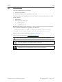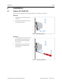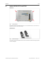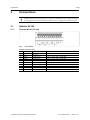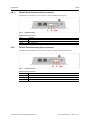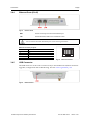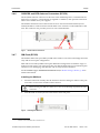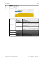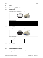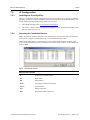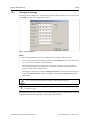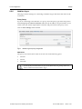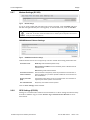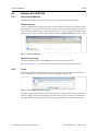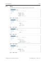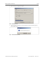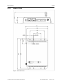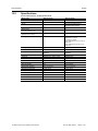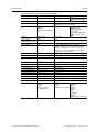
1
USER MANUAL
Netbiter® EasyConnect Gateway
Doc ID: HMSI-168-92
Version: 4.00
HALMSTAD • CHICAGO • KARLSRUHE • TOKYO • BEIJING • MILANO • MULHOUSE • COVENTRY • PUNE • COPENHAGEN • RAVENSBURG
HMS Industrial Networks
Mailing address: Box 4126, 300 04 Halmstad, Sweden
Visiting address: Stationsgatan 37, Halmstad, Sweden
E-mail: [email protected]
Web: www.netbiter.com
Important User Information
Liability
Every care has been taken in the preparation of this manual. Please inform HMS Industrial Networks AB of any inaccuracies or omissions. The data and illustrations found in this document are not binding. We, HMS Industrial Networks AB, reserve the right to modify our products in line with our policy of continuous product development. The
information in this document is subject to change without notice and should not be considered as a commitment by
HMS Industrial Networks AB. HMS Industrial Networks AB assumes no responsibility for any errors that may appear in this document.
There are many applications of this product. Those responsible for the use of this device must ensure that all the
necessary steps have been taken to verify that the applications meet all performance and safety requirements including any applicable laws, regulations, codes, and standards.
HMS Industrial Networks AB will under no circumstances assume liability or responsibility for any problems that
may arise as a result from the use of undocumented features, timing, or functional side effects found outside the
documented scope of this product. The effects caused by any direct or indirect use of such aspects of the product
are undefined, and may include e.g. compatibility issues and stability issues.
The examples and illustrations in this document are included solely for illustrative purposes. Because of the many
variables and requirements associated with any particular implementation, HMS Industrial Networks AB cannot assume responsibility for actual use based on these examples and illustrations.
Intellectual Property Rights
HMS Industrial Networks AB has intellectual property rights relating to technology embodied in the product described in this document. These intellectual property rights may include patents and pending patent applications in
the USA and other countries.
Trademark Acknowledgements
Netbiter® is a registered trademark of HMS Industrial Networks AB. Java is a registered trademark of Oracle and/or
its affiliates. All other trademarks are the property of their respective holders.
This is a class A product. In a domestic environment this product may cause radio interference in
which case the user may be required to take adequate measures.
This product contains ESD (Electrostatic Discharge) sensitive parts that may be damaged if ESD control procedures are not followed. Static control precautions are required when handling the product.
Failure to observe this may cause damage to the product.
Copyright © 2015 HMS Industrial Networks AB. All rights reserved.
Netbiter® EasyConnect Gateway User Manual
Doc ID: HMSI-168-92 Version: 4.00
Table of Contents
1
2
3
4
5
6
7
8
Page
Preface ............................................................................................................................... 3
1.1
About This Document.....................................................................................................3
1.2
Related Documents .......................................................................................................3
1.3
Document history...........................................................................................................3
1.4
Conventions ..................................................................................................................4
Installation ........................................................................................................................ 5
2.1
Netbiter EC150/EC250 ...................................................................................................5
2.2
Netbiter EC220, EC310 and EC350.................................................................................6
Connections ..................................................................................................................... 7
3.1
Netbiter EC150 ..............................................................................................................7
3.2
Netbiter EC220 ..............................................................................................................9
3.3
Netbiter EC250 ............................................................................................................12
3.4
Netbiter EC310/EC350 .................................................................................................15
3.5
Power Supply ..............................................................................................................19
LED Indicators ............................................................................................................... 20
4.1
Netbiter EC150 ............................................................................................................20
4.2
Netbiter EC220 ............................................................................................................21
4.3
Netbiter EC250 ............................................................................................................22
4.4
Netbiter EC310 ............................................................................................................23
4.5
Netbiter EC350 ............................................................................................................24
Wiring Examples ........................................................................................................... 26
5.1
Netbiter EC150/EC250 .................................................................................................26
5.2
Netbiter EC220 ............................................................................................................26
5.3
Netbiter EC310/EC350 .................................................................................................27
GPS ................................................................................................................................... 29
6.1
Connecting GPS Devices .............................................................................................29
6.2
Activating the GPS function ..........................................................................................29
Ethernet Network Setup .............................................................................................. 30
7.1
Static/Dynamic IP Addressing .......................................................................................30
7.2
IP Configuration ...........................................................................................................31
Activation ........................................................................................................................ 33
8.1
Adding the Gateway to Netbiter Argos ...........................................................................33
Netbiter® EasyConnect Gateway User Manual
Doc ID: HMSI-168-92
Version: 4.00
Table of Contents
9
Local Configuration...................................................................................................... 34
9.1
Connecting to the Web Server ......................................................................................34
9.2
Netbiter EC150/EC250 .................................................................................................35
9.3
Netbiter EC310/EC350 .................................................................................................40
10 Netbiter Update (EC150/EC250)................................................................................. 45
11 EtherNet/IP Implementation ....................................................................................... 48
11.1
Client ..........................................................................................................................48
11.2
Adapter .......................................................................................................................49
12 Technical Data................................................................................................................ 51
12.1
Dimensions .................................................................................................................51
12.2
Specifications ..............................................................................................................56
12.3
Regulatory notices .......................................................................................................58
Netbiter® EasyConnect Gateway User Manual
Doc ID: HMSI-168-92
Version: 4.00
Preface
3 (60)
1
Preface
1.1
About This Document
This manual describes how to install and configure Netbiter EasyConnect gateways.
For additional related documentation and file downloads, please visit the Netbiter support website at www.netbiter.com/support.
1.2
Related Documents
Related documents
1.3
Document
Netbiter EasyConnect Gateway Installation Guides
Author
HMS
Netbiter Argos Administration Manual
HMS
Netbiter Remote Access User Manual
HMS
Document history
Summary of recent changes
Change
Where (section no.)
Updated section on EC350 LED indicators.
4.5
Replaced D-sub graphic for EC220.
3.2.3
Changed “physical network” to “logical network”.
3.4.4, 9.3.5
Updated IP configuration section.
7.2
Updated local configuration section.
9
Updated class attribute descriptions.
11.2.2
Added info about proxy support.
12.2
Updated screenshots in most sections.
—
Revision list
Version
Date
Author
Description
1.00
1.10
Nov 2012
Mar 2013
SDa
SDa
First official release.
New chapter on Ethernet installation.
2.00
2.10
November 2013
January 2014
SDa
SDa
Added EC350.
Removed EC150-M. Removed info on relay in EC150.
2.11
April 2014
SDa
Minor correction to dimensions.
Added Japanese approval information.
2.20
May 2014
SDa
Added EC310. Updated LEDs for EC350.
2.30
September 2014
SDa
Certifications updated for EC310/EC350.
2.40
November 2014
SDa
Added EtherNet/IP support. Updated specs for EC3xx.
2.50
December 2014
ThN
Changed tolerance values.
3.00
May 2015
ThN
Multiple corrections and updates.
Revised document structure and layout.
3.10
June 2015
ThN
Added info on symbolic segment addressing.
4.00
Sep 2015
ThN
Misc. corrections and updates
New layout
Netbiter® EasyConnect Gateway User Manual
Doc ID: HMSI-168-92
Version: 4.00
Preface
1.4
4 (60)
Conventions
Unordered (bulleted) lists are used for:
•
Itemized information
•
Instructions that can be carried out in any order
Ordered (numbered or alphabetized) lists are used for instructions that must be carried
out in sequence:
1.
First do this,
2.
Then open this dialog, and
a.
set this option...
b.
...and then this one.
Bold typeface indicates interactible parts, such as connectors and switches on the hardware, or menus and buttons in a graphical user interface.
Monospaced text is used to indicate program code and other
kinds of data input/output such as configuration scripts.
This is a cross-reference within this document: Conventions, p. 4
This is an external link (URL): www.hms-networks.com
This is additional information which may facilitate installation and/or operation.
This instruction must be followed to avoid a risk of reduced functionality and/or damage to the equipment, or to avoid a network security risk.
Caution
This instruction must be followed to avoid a risk of personal injury.
Netbiter® EasyConnect Gateway User Manual
Doc ID: HMSI-168-92
Version: 4.00
Installation
5 (60)
2
Installation
2.1
Netbiter EC150/EC250
Netbiter EC150 and EC250 are supplied ready for mounting on a DIN rail.
Mounting
1.
Hook the unit onto the upper lip
of the rail.
2.
Press the unit towards the rail until it snaps into place.
Fig. 1
Mounting on DIN rail
Fig. 2
Removing from DIN rail
Removing
1.
Insert a flat-head screwdriver into
the slotted tab on the bottom of
the unit and pull the tab gently
downwards.
2.
Pull the bottom end of the unit
free of the rail and lift the unit
from the rail.
Netbiter® EasyConnect Gateway User Manual
Doc ID: HMSI-168-92
Version: 4.00
Installation
2.2
6 (60)
Netbiter EC220, EC310 and EC350
Wall Mount
Fig. 3
EC350 wall mount
The Netbiter EC220, EC310 and EC350 can be screw-mounted directly to a flat surface using the screw holes in the metal housing.
DIN Rail Mount
Fig. 4
DIN rail mounting kit
The Netbiter EC220, EC310 and EC350 can also be mounted on a DIN rail using an optional rail mounting kit.
Netbiter® EasyConnect Gateway User Manual
Doc ID: HMSI-168-92
Version: 4.00
Connections
3
7 (60)
Connections
Netbiter EasyConnect gateways can be connected to Modbus devices via different interfaces and physical connections. Which interface(s) to use is configured in Netbiter Argos.
3.1
Netbiter EC150
3.1.1
Terminal block (12–pin)
Fig. 5
Terminal block
Terminal block connections
Pin
24
Label
Vin+
Function
Power 9–24 VDC/VAC
23
Vin-
PE ground
22
DI:DI 2
Digital input #2
Low = 0–2 VDC, High = 10–24 VDC
21
DI:DI 1
Digital input #1
Low = 0–2 VDC, High = 10–24 VDC
20
DI:COM
Digital input common
17
16
15
14
13
RS-232:RX
RS-232:TX
COM
RS-485:A
RS-485:B
RS-232 Receive
RS-232 Transmit
Serial interface common
RS-485 Line A
RS-485 Line B
Netbiter® EasyConnect Gateway User Manual
Note
EC150 can optionally be powered by 9–24 VAC.
Shared between RS-232 and RS485
Doc ID: HMSI-168-92
Version: 4.00
Connections
3.1.2
8 (60)
D-sub Connector
The 9-pin male D-sub connector provides an RS-232 interface for Modbus RTU.
D-sub connector pin layout
3.1.3
Pin
1
Function
CD (Carrier Detect)
2
Rx (Receive)
3
Tx (Transmit)
4
DTR (Data Terminal Ready)
5
6
GND
DSR (Data Set Ready)
7
RTS (Request To Send)
8
CTS (Clear To Send)
9
RI (Ring Indicator)
1 (male) 5
6
Fig. 6
9
D-sub connector
Ethernet Connector
The RJ-45 socket provides Ethernet network connection. It also supports Modbus TCP via
Ethernet, which can be used at the same time as Modbus RTU units on another interface.
Ethernet connector pin layout
Pin
1
2
3
4, 5, 7, 8
Function
TD+
TDRD+
Termination
6
RD-
1
Fig. 7
Netbiter® EasyConnect Gateway User Manual
8
Ethernet connector
Doc ID: HMSI-168-92
Version: 4.00
Connections
9 (60)
3.2
Netbiter EC220
3.2.1
Terminal Block (12–pin)
Fig. 8
Terminal block
Terminal block pin layout
Pin
+Vdc
Function
Power 12–24 VDC
GND
PE ground
AO:OUT
Analog output
0–10 VDC
AO.COM
Analog output common
Internally connected to GND
AI:AI 1
Analog input #1
PT100, current or voltage (selected with internal switch)
AI:AI 2
Analog input #2
AI:COM
Analog input common
Internally connected to GND
Low = 0–1 VDC, High = 9–24 VDC
DI:DI1
Digital input #1
DI:DI2
Digital input #2
DI:COM
Digital input common
Relay:COM
Relay output common
Relay:NO
Normally open connected
Note
Rated load: 1 A @ 24 VDC
Analog Input Configuration Switches
Fig. 9
EC220 DIP switch
The analog inputs are configured with two DIP switches inside the unit. Take care not to
damage the antenna cable when opening/closing the cover.
EC220 DIP switch setting
Setting
Function
Note
PT100
Temperature sensor (default)
-50 to +150 °C
0–20 mA
Current
Input resistance 270 Ω
0–10 VDC
Voltage
Input resistance 280 Ω
Netbiter® EasyConnect Gateway User Manual
Doc ID: HMSI-168-92
Version: 4.00
Connections
3.2.2
10 (60)
RS-485 Serial Interface (3–pin Connector)
The RS-485 serial interface can be used to connect Modbus RTU devices.
Fig. 10
RS-485 connector
RS-485 connector pin layout
3.2.3
Pin
A
B
Function
RS-485 A line
RS-485 B line
COM
RS-485 common
D-sub Connector
The 9-pin female D-sub connector provides an RS-232 interface for Modbus RTU and for
connecting a GPS receiver.
D-sub connector pin layout
3.2.4
Pin
1
Function
CD (Carrier Detect)
2
Rx (Receive)
3
Tx (Transmit)
4
DTR (Data Terminal Ready)
5
6
GND
DSR (Data Set Ready)
7
RTS (Request To Send)
8
CTS (Clear To Send)
9
RI (Ring Indicator)
5 (female) 1
9
Fig. 11
6
D-sub connector
Antenna Connector
The antenna connector is a standard SMA screw connector. Optional external antennas
are available from your supplier.
Netbiter® EasyConnect Gateway User Manual
Doc ID: HMSI-168-92
Version: 4.00
Connections
3.2.5
11 (60)
SIM Card
Installing the SIM Card
1.
Push the yellow button next to the SIM card holder and remove the holder.
2.
Place the SIM card into the holder. Observe the correct position of the cut-off corner
and the contact surfaces.
3.
Insert the SIM card holder with the SIM card.
SIM Card configuration
The SIM card must be configured in Netbiter Argos before it can be used.
When using a SIM card not issued by HMS, make sure that the SIM card has a mobile data
plan and allows text messaging and that PIN code security has been disabled.
See the Netbiter Argos Administration Manual for further information.
Netbiter® EasyConnect Gateway User Manual
Doc ID: HMSI-168-92
Version: 4.00
Connections
12 (60)
3.3
Netbiter EC250
3.3.1
Terminal Block (12-pin)
Fig. 12
Terminal block
Terminal block pin layout
3.3.2
Pin
24
23
Label
V+
GND
Function
Power 9–24 VDC
PE ground
Note
22
DI:COM
Digital input common
21
DI:DI 1
Digital input #1
Low = 0–2 VDC, High = 10–24 VDC
20
DI:DI 2
Digital input #2
Low = 0–2 VDC, High = 10–24 VDC
19
18
17
16
RS-232:RX
RS-232:TX
COM
RS-422:RD(A)
RS-232 Receive
RS-232 Transmit
Serial interface common
RS-422 Receive A
15
RS-422:RD(B)
RS-422 Receive B
14
RS-485:TD(A)
RS-422:TD(A)
RS-485 Line A
RS-422 Transmit A
13
RS-485:TD(B)
RS-422:TD(B)
RS-485 Line B
RS-422 Transmit B
Shared between RS232/422/485
D-sub Connector
The 9-pin D-sub connector provides an RS-232 interface for Modbus RTU and for connecting a GPS receiver.
D-sub connector pin layout
Pin
1
Function
CD (Carrier Detect)
2
Rx (Receive)
3
Tx (Transmit)
4
DTR (Data Terminal Ready)
5
6
GND
DSR (Data Set Ready)
7
RTS (Request To Send)
8
CTS (Clear To Send)
9
RI (Ring Indicator)
Netbiter® EasyConnect Gateway User Manual
1 (male) 5
6
Fig. 13
9
D-sub connector
Doc ID: HMSI-168-92
Version: 4.00
Connections
3.3.3
13 (60)
Ethernet Connector
The RJ-45 socket provides Ethernet network connection. It also supports Modbus TCP via
Ethernet, which can be used at the same time as Modbus RTU units on another interface.
Ethernet connector pin layout
Pin
1
2
3
4, 5, 7, 8
Function
TD+
TDRD+
Termination
6
RD-
1
Fig. 14
3.3.4
8
Ethernet connector
Antenna Connector
The antenna connector is a standard SMA screw connector. Optional external antennas
are available from your supplier.
Netbiter® EasyConnect Gateway User Manual
Doc ID: HMSI-168-92
Version: 4.00
Connections
3.3.5
14 (60)
SIM Card
Installing the SIM Card
1.
Push the yellow button next to the SIM card holder and remove the holder.
2.
Place the SIM card into the holder. Observe the correct position of the cut-off corner
and the contact surfaces.
3.
Insert the SIM card holder with the SIM card.
SIM Card configuration
The SIM card must be configured in Netbiter Argos before it can be used.
When using a SIM card not issued by HMS, make sure that the SIM card has a mobile data
plan and allows text messaging and that PIN code security has been disabled.
See the Netbiter Argos Administration Manual for further information.
Netbiter® EasyConnect Gateway User Manual
Doc ID: HMSI-168-92
Version: 4.00
Connections
15 (60)
3.4
Netbiter EC310/EC350
3.4.1
Terminal Block (11-pin)
Fig. 15
Terminal block
Terminal block pin layout
10
9
8
Label
Analog In
Pin
11
6
5
4
3
DI/Pulse In
7
1
Relay
2
Function
Analog Input Common
Note
COM
AI4
Analog Input 4
0–20 mA or 0–10 VDC
AI3
Analog Input 3
0–20 mA or 0–10 VDC or PT100
AI2
Analog Input 2
0–20 mA or 0–10 VDC
AI1
Analog Input 1
0–20 mA or 0–10 VDC or PT100
DI2-
Digital Input 2
DI2+
Digital Input 2 current source
DI1-
Digital Input 1
DI1+
Digital Input 1 current source
COM
Relay output common, isolated
NO
Relay output, NO, isolated
Dry contact type
Rated load: 1 A @ 24 VDC
The analog inputs can be configured in Netbiter Argos for either current, voltage or
PT100 (temperature sensor).
The digital inputs are of the “dry contact” type which do not require any control voltage
and will function with a switch or breaker.
Do not connect a power source to the digital inputs, as this may damage the unit.
The relay output must be supplied from an isolating transformer using a secondary
listed fuse rated at maximum 3.3 A and minimum 30 VDC.
Netbiter® EasyConnect Gateway User Manual
Doc ID: HMSI-168-92
Version: 4.00
Connections
3.4.2
16 (60)
RS-485 Serial Interface (3-pin connector)
The RS-485 serial interface can be used to connect Modbus RTU devices.
Fig. 16
RS-485 connector
RS-485 connector pin layout
3.4.3
Pin
A
B
Function
RS-485 A line
RS-485 B line
COM
RS-485 common
RS-232 Serial Interface (3-pin connector)
The RS-232 serial interface can be used to connect a single Modbus RTU device.
Fig. 17
RS-232 connector
RS-232 connector pin layout
Pin
Rx
Function
Receive (input)
Tx
Transmit (output)
GND
Signal ground
Netbiter® EasyConnect Gateway User Manual
Doc ID: HMSI-168-92
Version: 4.00
Connections
3.4.4
17 (60)
Ethernet Ports (RJ-45)
Fig. 18
Ethernet Ports
WAN
Used for connecting to the Internet and Netbiter Argos
LAN
Used for EtherNet/IP, Modbus TCP and Remote Access
Do not connect the LAN and WAN ports to the same logical network.
Ethernet connector pin layout
Pin
1
2
3
4, 5, 7, 8
Function
TD+
TDRD+
Termination
6
RD-
1
Fig. 19
3.4.5
8
Ethernet connector
USB Connector
The USB connector can be used to connect locally to the Netbiter EC310/350 for firmware
upgrades, configuration and troubleshooting. See also Select Login Method, p. 40.
Fig. 20
USB connector
Netbiter® EasyConnect Gateway User Manual
Doc ID: HMSI-168-92
Version: 4.00
Connections
3.4.6
18 (60)
3G/GPRS and GPS Antenna Connectors (EC350)
The 3G/GPRS antenna connector on the front of the Netbiter EC350 is a standard female
SMA screw connector. A stub antenna is supplied as standard1, and optional external antennas are available from your supplier.
The Netbiter EC350 also has a built-in GPS receiver. An external GPS antenna (not included) should be connected to the female SMA screw connector on the underside of the
unit. The connector also provides power for active GPS antennas.
Fig. 21
3.4.7
EC350 antenna connectors
SIM Card (EC350)
The Netbiter SIM cards provided by HMS will load the correct network settings automatically and do not require configuration.
SIM cards not issued by HMS will require additional configuration in Netbiter Argos or
in the local web pages. You must also make sure that the SIM card has a mobile data plan
and allows text messaging, and that PIN code security has been disabled.
See the Netbiter Argos Administration Manual and/or Modem Settings (EC350), p. 44 for
further information.
Installing the SIM Card
1.
Insert the SIM card carefully into the EC350 as shown in the figure. Observe the position of the cut-off corner and the contact surfaces.
When inserting the SIM card, make sure it does not accidentally slip behind the SIM
card holder.
2.
Push the SIM card firmly downwards until it clicks into place.
Fig. 22
1.
Installing the SIM card
Antenna is not included when sold in the U.S.
Netbiter® EasyConnect Gateway User Manual
Doc ID: HMSI-168-92
Version: 4.00
Connections
3.5
19 (60)
Power Supply
Always make sure that the power supply is correctly connected and of the correct type.
Connecting power with reverse polarity or using the wrong type of power supply may
damage the unit.
Netbiter EC150 and EC250
Fig. 23
EC150/EC250 power supply connection
Connect 9–24 VDC to Vin+ (EC150) or V+ (EC250), and connect ground to GND.
Netbiter EC150 can alternatively be powered by 9–24 VAC.
Netbiter EC220
Fig. 24
EC220 power supply connection
Connect 9–24 VDC to +VDC, and connect ground to GND.
Netbiter EC310 and EC350
Fig. 25
EC310/EC350 power supply connection
Connect 12–48 VDC to + (plus), and connect ground to - (minus).
Netbiter® EasyConnect Gateway User Manual
Doc ID: HMSI-168-92
Version: 4.00
LED Indicators
20 (60)
4
LED Indicators
4.1
Netbiter EC150
Fig. 26
EC150 LED indicators
LED Indication
Meaning
OFF
No power
Orange/green
System is starting up
Green (3 flashes)
System is operating normally
Red (2 flashes)
Invalid network settings
• DHCP: Check that there is a working DHCP server on the
network.
• Static IP: Check that the IP address, default gateway and
DNS are correctly set.
• If a proxy is used, check that the proxy settings are correct.
Module Status
Serial Link Status
Activity/Collision
Link
Red (3 flashes)
No connection to Netbiter Argos
Flashing green
• Check the network settings.
• If a proxy is used, check that the proxy settings are correct.
• Check that at least one of ports 443, 80 or 5222 are open in
the firewall.
Receiving serial packet
Flashing red
Transmitting serial packet
Flashing green
Receiving Ethernet packet
Flashing red
Ethernet collision
Steady green
10 Mbps Ethernet network detected
Steady orange
100 Mbps Ethernet network detected
Netbiter® EasyConnect Gateway User Manual
Doc ID: HMSI-168-92
Version: 4.00
LED Indicators
4.2
21 (60)
Netbiter EC220
All LED indicators will be lit while the gateway is starting up. After the startup sequence
has completed they will indicate system status.
Fig. 27
EC220 LED indicators
LED Indication
Power
Status
Meaning
Off
No power
Green (steady)
Unit has power
Off
Normal operation
Red (1 flash)
SIM card not registered on HMS Home Network2
• Check that the SIM card is correctly inserted and undamaged and
that PIN security is disabled.
• Check that there is mobile network coverage for your operator.
Red (2 flashes)
Invalid network settings
• Check that the correct APN (Access Point Name) has been set in
Netbiter Argos.
Red (3 flashes)
No connection to Netbiter Argos
• Check that the mobile network provider grants access to port 5222.
Running
GSM Signal
Off
Contact Netbiter support
Green (flashing)
Normal operation
Off
Contact Netbiter support
Green (1 flash)
Poor mobile network signal
Green (2 flashes)
• Make sure the antenna is correctly installed and pointing upwards.
• Try a different antenna placement.
• Use an external antenna.
Acceptable mobile network signal
Green (3 flashes)
Good mobile network signal
2.
The Netbiter SIM card will automatically try to connect to a network in the global HMS “home network” group of operators. A list of these network operators can be found at the Netbiter support website.
Netbiter® EasyConnect Gateway User Manual
Doc ID: HMSI-168-92
Version: 4.00
LED Indicators
4.3
22 (60)
Netbiter EC250
Fig. 28
EC250 LED indicators
The Module Status LED alternates between displaying system status and mobile network
signal strength for 2 seconds each in a 4-second cycle. If a mobile network connection has
not been set up, the LED will stay unlit during the second part of the cycle.
LED Indication
Meaning
OFF
No power
Orange/green
System is starting up (ca. 40 seconds)
Red (1 flash)
SIM card not registered on HMS Home Network3
• Check that the SIM card is correctly inserted and undamaged, and that PIN security is disabled.
• Check that there is mobile network coverage for your
operator
Red (2 flashes)
Invalid network settings
Mobile
• Check that the correct APN (Access Point Name) has been
set in Netbiter Argos.
Ethernet
• DHCP: Check that there is a working DHCP server on the
network.
• Static IP: Check that the IP address, default gateway and
DNS are correctly set.
• If a proxy is used, check that the proxy settings are correct.
Module Status (1)
Red (3 flashes)
No connection to Netbiter Argos
Mobile
• Check that the mobile network provider grants access to
port 5222.
Green (1 flash)
Ethernet
• Check the network settings.
• If a proxy is used, check that the proxy settings are correct.
• Check that at least one of ports 443, 80 or 5222 are open in
the firewall.
Poor mobile network signal
Green (2 flashes)
• Make sure the antenna is correctly installed and pointing
upwards.
• Try a different antenna placement.
• Use an external antenna.
Acceptable mobile network signal
Module Status (2)
Serial Status
Ethernet Activity
Ethernet Link
Green (3 flashes)
Good mobile network signal
Steady orange
System is starting up
Flashing green
Receiving serial packet
Flashing red
Transmitting serial packet
Flashing green
Receiving Ethernet packet
Steady green
10 Mbps Ethernet network detected
Steady orange
100 Mbps Ethernet network detected
3.
The Netbiter SIM card will automatically try to connect to a network in the global HMS “home network” group of operators. A list of these network operators can be found at the Netbiter support website.
Netbiter® EasyConnect Gateway User Manual
Doc ID: HMSI-168-92
Version: 4.00
LED Indicators
4.4
23 (60)
Netbiter EC310
Fig. 29
EC350 LED indicators
LED Indication
RS485/RS232
Uplink/WAN
Meaning
Off
Red (steady)
Port not in use
Port failure – contact Netbiter support
Green (steady)
Port enabled in Netbiter Argos
Red (steady)
Incorrect IP address settings
• DHCP: Check for a working DHCP server on the network.
• Static IP: Check that the IP address, default gateway and DNS are
correctly set.
Red (flashing)
No connection to Netbiter Argos
• Check your network settings.
• Check that port 443 is open in the firewall.
Gateway
Power
Fig. 30
Green (steady)
Connected to Netbiter Argos
Off
No power, or unit is starting up
Red (steady)
Hardware failure – contact Netbiter support
Red (flashing)
Application failure – contact Netbiter support
Green (flashing)
Firmware update in progress
Green (steady)
Unit is operational
Off
No power
Green (steady)
Unit has power
Ethernet Link LEDs
LED Indication
Meaning
Off
Orange (flashing)
No Ethernet traffic
Activity on 10 Mbit/s network
Green (flashing)
Activity on 100 Mbit/s network
Netbiter® EasyConnect Gateway User Manual
Doc ID: HMSI-168-92
Version: 4.00
LED Indicators
4.5
24 (60)
Netbiter EC350
All LED indicators will light up while the gateway is starting up. After the startup sequence has completed they will indicate system status.
Pressing and releasing the MODE button will temporarily change the function of the top
5 LED indicators to show the strength of the mobile network signal. After 60 seconds the
indicators will revert to the default mode (system status).
Fig. 31
EC350 LED indicators
System Status (default mode)
LED Indication
RS485/RS232
Uplink/WAN
Meaning
Off
Red (steady)
Port not in use
Port failure – contact Netbiter support
Green (steady)
Port enabled in Netbiter Argos
Red (steady)
Incorrect IP address settings
• DHCP: Check for a working DHCP server on the network.
• Static IP: Check that the IP address, default gateway and DNS are
correctly set.
Red (flashing)
No connection to Netbiter Argos
• Check your network settings.
• Check that port 443 is open in the firewall.
Modem
Green (steady)
Connected to Netbiter Argos
Off
Modem disabled
Red (steady)
Modem failure – contact Netbiter support
Red (flashing)
SIM card failure
• Check that the SIM card is correctly inserted and undamaged.
Gateway
Power
Orange (steady)
PIN code is activated for the SIM card
Orange (flashing)
• Disable the PIN code on the SIM card.
APN (Access Point Name) not set
Green (flashing)
Searching for mobile network
Green (steady)
Connected to mobile network
Off
No power, or unit is starting up
Red (steady)
Hardware failure – contact Netbiter support
Red (flashing)
Application failure – contact Netbiter support
Green (flashing)
Firmware update in progress
Green (steady)
Unit is operational
Off
No power
Green (steady)
Unit has power
Netbiter® EasyConnect Gateway User Manual
Doc ID: HMSI-168-92
Version: 4.00
LED Indicators
25 (60)
Fig. 32
EC350 LED indicators and mode switch
Signal Strength (shown for 60 seconds when MODE switch is pressed)
LED indication
Meaning
1 red LED (flashing)
No/unknown signal
1 orange LED (flashing)
Poor mobile network signal
1 green LED (flashing)
• Make sure the antenna is correctly installed and pointing upwards.
• Try a different antenna placement.
• Use an external antenna.
Acceptable mobile network signal
2–5 green LEDs (flashing)
Good to optimum mobile network signal
Fig. 33
Ethernet Link LEDs
LED Indication
Meaning
Off
Orange (flashing)
No Ethernet traffic
Activity on 10 Mbit/s network
Green (flashing)
Activity on 100 Mbit/s network
Netbiter® EasyConnect Gateway User Manual
Doc ID: HMSI-168-92
Version: 4.00
Wiring Examples
26 (60)
5
Wiring Examples
5.1
Netbiter EC150/EC250
EC150/EC250
DI:DI 1/2
9–24 VDC
0 VDC
Fig. 34
5.2
DI:COM
Digital Input
Netbiter EC220
EC220
+
AI:AI 1/2
-
Fig. 35
PT100
0-20 mA
0–10 VDC
AI:COM
0-10 V
Analog Input – Voltage Sensor
EC220
+
0–20 mA
AI:AI 1/2
PT100
0-20 mA
-
Fig. 36
AI:COM
0-10 V
Analog Input – 2-wire Current Sensor
EC220
+
0–20 mA
-
OUT
AI:AI 1/2
0-20 mA
AI:COM
Fig. 37
PT100
0-10 V
Analog Input – 3-wire Current Sensor
EC220
+
0–20 mA
-
Fig. 38
OUT
AI:AI 1/2
GND
AI:COM
PT100
0-20 mA
0-10 V
Analog Input – 4-wire Current Sensor
EC220
AI:AI 1/2
AI:COM
Fig. 39
PT100
0-20 mA
PT100
0-10 V
Analog Input – Temperature Sensor
Netbiter® EasyConnect Gateway User Manual
Doc ID: HMSI-168-92
Version: 4.00
Wiring Examples
27 (60)
EC220
DI:DI 1/2
9–24 VDC
0 VDC
Fig. 40
DI:COM
Digital Input
EC220
Analog load 0–10 V
Max load resistance = 2 kΩ
AO:OUT
AO:COM
Fig. 41
Analog Output
EC220
24 V DC/AC
Load
Fuse
0V
Fig. 42
Relay:NO
Relay:COM
Relay Output
The relay output must be supplied from an isolating transformer using a secondary
listed fuse rated at maximum 3.3 A and minimum 30 VDC.
5.3
Netbiter EC310/EC350
EC310 / EC350
+
Analog In:AI1 (AI2/3/4)
-
Analog In:COM
0–10 VDC
Fig. 43
Analog Input – Voltage Sensor
EC310 / EC350
+
0–20 mA
Analog In:AI1 (AI2/3/4)
-
Fig. 44
Analog In:COM
Analog Input – 2-wire Current Sensor
EC310 / EC350
+
-
0–20 mA
OUT
Analog In:AI1 (AI2/3/4)
Analog In:COM
Fig. 45
Analog Input – 3-wire Current Sensor
Netbiter® EasyConnect Gateway User Manual
Doc ID: HMSI-168-92
Version: 4.00
Wiring Examples
28 (60)
EC310 / EC350
+
0–20 mA
-
Fig. 46
OUT
Analog In:AI1 (AI2/3/4)
GND
Analog In:COM
Analog Input – 4-wire Current Sensor
EC310 / EC350
Analog In:AI1 (AI3)
PT100
Analog In:COM
Fig. 47
Analog Input – Temperature Sensor
EC310 / EC350
DI/Pulse In:DI1+ (DI2+)
DI/Pulse In:DI1- (DI2-)
Fig. 48
Digital Input
Do not connect a power source to the digital inputs on a Netbiter EC310/EC350 as
this may damage the unit.
EC310 / EC350
24 V DC/AC
0V
Fig. 49
Load
Fuse
Relay:NO
Relay:COM
Relay Output
The relay output must be supplied from an isolating transformer using a secondary
listed fuse rated at maximum 3.3 A and minimum 30 VDC.
Netbiter® EasyConnect Gateway User Manual
Doc ID: HMSI-168-92
Version: 4.00
GPS
29 (60)
6
GPS
6.1
Connecting GPS Devices
6.1.1
Netbiter EC220
Connecting a GPS device to a Netbiter EC220 requires a cable with a 9-pin male D-sub
connector to connect to the RS-232 port.
1 (male) 5
6
Fig. 50
9
D-sub connector
GPS cable pin assignment
6.1.2
EC220 RS-232 port
GPS device
2
Rx (Receive)
Tx
3
Tx (Transmit)
Rx
5
GND
GND
Netbiter EC250
Connecting a GPS device to a Netbiter EC250 requires a cable with a 9-pin female D-sub
connector to connect to the RS-232 port.
5 (female) 1
9
Fig. 51
6
D-sub connector
GPS cable pin assignment
6.1.3
EC250 RS-232 port
GPS device
2
Rx (Receive)
Tx
3
Tx (Transmit)
Rx
5
GND
GND
Netbiter EC350
The Netbiter EC350 has a built-in GPS receiver. To use the GPS function, connect a suitable GPS antenna (not included) to the unit.
6.2
Activating the GPS function
GPS functionality must be activated in Netbiter Argos before it can be used. See the Netbiter Argos Administration Manual for more information.
Netbiter® EasyConnect Gateway User Manual
Doc ID: HMSI-168-92
Version: 4.00
Ethernet Network Setup
7
30 (60)
Ethernet Network Setup
Netbiter EasyConnect gateways should only be installed in networks with firewall
protection. Contact your network administrator if in doubt.
Netbiter EasyConnect gateways require outbound (outgoing) access on the TCP ports
listed below to connect to Netbiter Argos.
Ports used to connect to Netbiter Argos
Netbiter model
TCP ports
EC310, EC350
443
EC150, EC250
5222, 443, 80
Connection attempts will be made to 3 different servers with a timeout of 30 seconds each.
This means that it may take up to 4 min 30 sec to establish a connection for EC150/220/250
(3 ports x 3 servers x 30 seconds).
The following ports may also need to be opened in the firewall:
7.1
502
Default port for Modbus TCP
8080
Extra web server
Static/Dynamic IP Addressing
When using static IP addressing the network settings are configured using the IPconfig
utility. See IP Configuration, p. 31.
When using DHCP (the default setting), there is no need to configure any of the IP address related settings.
If the network uses a proxy to connect to the Internet you also need to set up the proxy
configuration in the local configuration web interface. See Local Configuration, p. 34.
Netbiter® EasyConnect Gateway User Manual
Doc ID: HMSI-168-92
Version: 4.00
Ethernet Network Setup
31 (60)
7.2
IP Configuration
7.2.1
Installing the IPconfig Utility
IPconfig is a Windows-based configuration utility for TCP/IP network settings in Netbiter
gateways. It detects connected Netbiter gateways and lets the user set the IP address, netmask, default gateway, DNS and hostname for each unit.
7.2.2
1.
Download IPConfig from www.netbiter.com/support.
2.
Extract the contents of the zip archive in a folder on your computer and double-click
the executable file to run it.
Scanning for Connected Devices
Make sure that the Netbiter gateways to be installed are connected on the same Ethernet
subnet as the computer running IPconfig. Use standard Ethernet cables.
When the IPconfig utility is started it will scan the Ethernet network for Netbiter gateways. All detected units will be presented in a list in the main window. To refresh the list,
click on Scan.
Fig. 52
IPconfig main window
Main window columns
IP
IP address of the Netbiter gateway
SN
Subnet mask
GW
Default gateway
DHCP
Automatically managed IP configuration
Version
Firmware version
Type
Netbiter model name
MAC
Ethernet MAC address (System ID)
Netbiter® EasyConnect Gateway User Manual
Doc ID: HMSI-168-92
Version: 4.00
Ethernet Network Setup
7.2.3
32 (60)
Changing IP settings
To change the IP settings for a unit in the list, either double-click on it or select it and click
on Settings to open the configuration window.
Fig. 53
IPConfig settings
Notes
•
Do not enable DHCP if there is no DHCP server available on the network.
•
You can add a name for the Netbiter gateway in the Hostname field. Only characters
a-z, A-Z, 0–9 and _ (underscore) are allowed.
•
The default password for authentication of the new settings is admin for Netbiter
EC150, EC250, and WS series gateways. For Netbiter EC300 series gateways the default password is the activation code.
To change the password, check the Change password box and enter the current password in the Password field and the new password in the New password field, then
click on Set.
For security reasons, the password “admin” should always be changed.
Changing the password in IPconfig will not affect the password for logging in to the local
configuration pages.
Click Set to save the new settings and restart the Netbiter gateway. Please note it that may
take some time before the gateway is online again after a reboot.
Netbiter® EasyConnect Gateway User Manual
Doc ID: HMSI-168-92
Version: 4.00
Activation
33 (60)
8
Activation
8.1
Adding the Gateway to Netbiter Argos
Before a Netbiter EasyConnect gateway can be used it must be registered and activated
from a user account in Netbiter Argos.
For instructions on how to add a Netbiter gateway to Netbiter Argos, please refer to the
Netbiter Argos Administration Manual which can be downloaded from the Netbiter support website www.netbiter.com/support.
Fig. 54
Netbiter Argos
Netbiter® EasyConnect Gateway User Manual
Doc ID: HMSI-168-92
Version: 4.00
Local Configuration
9
34 (60)
Local Configuration
Local configuration is normally not required and should only be carried out when necessary. Please read the instructions below carefully.
All Netbiter EasyConnect gateways except EC220 contain a built-in local web server that
can be used for initial configuration and troubleshooting.
Netbiter Argos is the preferred way of configurating the gateway and should be used
whenever possible. The only settings that should be made using the local web pages are:
9.1
•
Proxy settings (if required)
•
Modem/Ethernet connection mode (EC250/EC350 only)
•
PIN code settings – if using a PIN code for the SIM card (EC250 only)
Connecting to the Web Server
The PC used to access the local configuration must be on the same Ethernet network subnet as the gateway. The PC can also be connected directly to the gateway using a crossover
Ethernet cable. This may require the IP address for the Ethernet interface on the PC to be
changed.
To connect to the web server in the Netbiter gateway, use the IPconfig utility to detect the
IP address of the gateway, see IP Configuration, p. 31.
Right-click on the gateway in IPconfig and select Open Web Interface to open its local
web server in your default browser. You can also type the IP address directly into the web
browser address field.
Fig. 55
IPconfig
Netbiter EC310 and EC350 also have a USB port that can be used for accessing the local
web server, see Select Login Method, p. 40.
Netbiter® EasyConnect Gateway User Manual
Doc ID: HMSI-168-92
Version: 4.00
Local Configuration
35 (60)
9.2
Netbiter EC150/EC250
9.2.1
Login
Enter the IP address of the gateway in a web browser to log in. The default user name is
admin, and the password is the activation code supplied with the unit.
Fig. 56
Local web server login
The only changes that should be made locally are the settings for the network connection,
modem settings (EC250) and firmware updates. All other settings are provided for troubleshooting and information purposes only and will not be synchronized with Netbiter
Argos.
9.2.2
Status
The Status page presents an overview of the current connection status.
Fig. 57
Status page
Netbiter® EasyConnect Gateway User Manual
Doc ID: HMSI-168-92
Version: 4.00
Local Configuration
9.2.3
36 (60)
Modbus Settings
Settings for Modbus communication. These settings should normally be made in Netbiter
Argos. See the Netbiter Argos Administration Manual for more information.
Fig. 58
9.2.4
Modbus Settings
Ethernet Settings
Fig. 59
Ethernet settings
These are the same settings as those entered in IPconfig, see IP Configuration, p. 31.
When DHCP is enabled the unit will automatically receive the settings for IP address, subnet mask, default gateway, and DNS. Contact your network administrator if in doubt.
Netbiter® EasyConnect Gateway User Manual
Doc ID: HMSI-168-92
Version: 4.00
Local Configuration
9.2.5
37 (60)
System Settings
Fig. 60
System settings
This page is mainly used when updating the firmware in the unit.
Updating Firmware
1.
Download the latest firmware from www.netbiter.com/support.
2.
Click on Browse and select the firmware file you downloaded.
3.
Click on Update to start the update.
Do not close the web page while the update is in progress.
The firmware in Netbiter EC150 and EC250 can alternately be uploaded via the RS-232 serial interface. See Netbiter Update (EC150/EC250), p. 45.
Netbiter® EasyConnect Gateway User Manual
Doc ID: HMSI-168-92
Version: 4.00
Local Configuration
9.2.6
38 (60)
Netbiter Argos
This page contains settings for connecting to Netbiter Argos and shows the status of the
connection.
Proxy Setup
If you are connecting to the Internet via a proxy, select the proxy type in the drop-down
menu Use proxy to connect to Internet and fill in the IP address, the port number to use
on the LAN side, and (if required) the username and password for the proxy server.
Click on Save settings when finished.
Fig. 61
Netbiter Argos and proxy configuration
WAN Ports
The proxy server must allow traffic on at least one of the following ports:
•
Port 443
•
Port 80
•
Port 5222
If none of the ports listed above are open on the WAN side, the gateway will not be
able to communicate with Netbiter Argos.
Netbiter® EasyConnect Gateway User Manual
Doc ID: HMSI-168-92
Version: 4.00
Local Configuration
9.2.7
39 (60)
Modem Settings (EC250)
Fig. 62
Modem settings
If you are using a SIM card with PIN code security activated, click on Enable and enter
the PIN code (provided by the card supplier). To test the PIN code, click on Test PIN.
This setting will not enable/disable PIN code security or change the PIN code on the
SIM card. To do that, install the SIM card in a mobile phone and follow the instructions from the manufacturer.
GPRS/Ethernet Failover Settings
Fig. 63
GPRS/Ethernet failover settings
Netbiter EC250 can be set to temporarily switch to mobile networking if Ethernet fails.
Connection mode
GPRS only: Ethernet disabled (default mode)
Ethernet failover to GPRS: Unit will automatically switch to GPRS if Ethernet
connection is lost
Ethernet only: GPRS modem disabled
Connection time before
restore to Ethernet
Sets the time before the gateway should retry the Ethernet connection after a
failover to GPRS. The cycle will be repeated until Ethernet communication has
been reestablished.
Access point name
(APN)
The identifying name used to connect to a mobile network. This information is
supplied by the network operator for the SIM card.
User name/Password
Required by some mobile network operators.
Click on Save settings when finished.
9.2.8
GPS Settings (EC250)
Settings for communication with an external GPS device. These settings should normally
be made in Netbiter Argos. See the Netbiter Argos Administration Manual for more
information.
Netbiter® EasyConnect Gateway User Manual
Doc ID: HMSI-168-92
Version: 4.00
Local Configuration
40 (60)
9.3
Netbiter EC310/EC350
9.3.1
Select Login Method
Netbiter EC310 and EC350 provide local access via either Ethernet or USB cable.
USB Connection
Connect a USB Micro B cable between the computer and the Netbiter EC310/EC350. After
the USB device driver has been installed a virtual network card will automatically be created, with an IP address in the range 169.254.200.xxx. The local configuration pages of the
gateway can now be accessed by entering the IP address 169.254.200.200 in a web browser.
Fig. 64
Network Connections
Ethernet Connection
Connect an Ethernet cable to the WAN socket on the Netbiter EC310/350.
See IP Configuration, p. 31 on how to find out the IP address of the Netbiter gateway.
9.3.2
Login
Enter the IP address of the gateway in a web browser to log in. The default user name is
admin, and the password is the activation code supplied with the unit.
Fig. 65
Local configuration web server login
The only changes that should be made locally are the settings for the network connection,
modem settings, and firmware updates. All other settings are provided for troubleshooting and informational purposes only and will not be synchronized with Netbiter Argos.
Netbiter® EasyConnect Gateway User Manual
Doc ID: HMSI-168-92
Version: 4.00
Local Configuration
9.3.3
41 (60)
Status
The Status tabs present the current configuration and connection status.
Fig. 66
Status – Overview
Fig. 67
Status – WAN
Fig. 68
Status – LAN
Fig. 69
Status – Modem
Fig. 70
Status – Uplink
Netbiter® EasyConnect Gateway User Manual
Doc ID: HMSI-168-92
Version: 4.00
Local Configuration
9.3.4
42 (60)
Network Settings – WAN
Fig. 71
WAN settings
The WAN interface should be enabled when connecting to Netbiter Argos via Ethernet.
The settings are the same as those entered in IPconfig, see IP Configuration, p. 31.
When DHCP is enabled the unit will automatically receive the settings for IP address, subnet mask, default gateway, and DNS. Contact your network administrator if in doubt.
Proxy Settings
Fig. 72
Proxy settings
If you are connecting to the Internet via a proxy, check the box Enable Proxy settings, select the proxy type in the drop-down menu Proxy protocol and fill in the IP address and
the port number to use for the proxy server.
If the proxy requires authentication, check the box Use Proxy authentication and fill in
the username and password.
Click on Save settings when finished.
For information about the supported proxy types, see Specifications, p. 56.
Netbiter® EasyConnect Gateway User Manual
Doc ID: HMSI-168-92
Version: 4.00
Local Configuration
9.3.5
43 (60)
Network Settings – LAN
The LAN interface must be enabled when using EtherNet/IP or Modbus TCP applications
and when using the Netbiter Remote Access service.
These settings can also be made in Netbiter Argos. See the Netbiter Argos Administration
Manual.
Fig. 73
LAN settings
Do not connect the LAN and WAN ports to the same logical network.
Click on Save settings when finished.
9.3.6
Firmware Update
Firmware updates can also be made through Netbiter Argos. See the Netbiter Argos Administration Manual.
Fig. 74
Firmware update
The Netbiter gateway must be connected to the Internet to ensure that the internal
clock has synchronized the time and date before updating the firmware.
1.
Download the latest firmware from www.netbiter.com/support.
2.
Click on Browse and select the firmware file you downloaded.
3.
Click on Start upgrade to start the update.
Do not close the web page while the update is in progress.
Netbiter® EasyConnect Gateway User Manual
Doc ID: HMSI-168-92
Version: 4.00
Local Configuration
9.3.7
44 (60)
Modem Settings (EC350)
Modem settings and information about the mobile connection.
These settings can also be made in Netbiter Argos. A SIM card with SMS capability is required. See the Netbiter Argos Administration Manual.
Fig. 75
Modem settings (EC350)
Use modem as primary
connection to Argos
When enabled, mobile networking will be used as default as long as the signal
strength is adequate. If the WAN interface is also enabled the gateway will
automatically switch to Ethernet networking if mobile communication is interrupted.
APN
The APN (Access Point Name) is the identifier for the mobile network. The APN is
supplied by the network operator for the SIM card.
User/Password
Required by some mobile network operators.
Click on Save settings when finished.
SIM cards with active PIN code security cannot be used in Netbiter EC350. The PIN
code cannot be disabled here or in Netbiter Argos. Install the SIM card in a mobile
phone and follow the instructions from the manufacturer to disable the PIN code.
Netbiter® EasyConnect Gateway User Manual
Doc ID: HMSI-168-92
Version: 4.00
Netbiter Update (EC150/EC250)
10
45 (60)
Netbiter Update (EC150/EC250)
The easiest way to update firmware is via Netbiter Argos, with the local configuration pages as a backup option if Netbiter Argos cannot be used. The firmware for Netbiter EC150
and EC250 can also be uploaded via the RS-232 serial (D-sub) interface using a free Windows-based software tool, Netbiter Update.
Updating Firmware with Netbiter Update
Requirements
•
Null modem cable
•
Computer with RS-232 serial interface (COM port)
1.
Download Netbiter Update from www.netbiter.com/support.
2.
Connect a null modem cable between the serial port on the computer and the D-sub
connector on the Netbiter gateway.
3.
Start Netbiter Update. The COM port should already be selected. Leave the Baudrate
setting at Auto.
Fig. 76
4.
Netbiter Update
Click on Browse and locate the firmware file you downloaded, then click Open.
Fig. 77
File dialog
Netbiter® EasyConnect Gateway User Manual
Doc ID: HMSI-168-92
Version: 4.00
Netbiter Update (EC150/EC250)
46 (60)
5.
Power OFF the Netbiter gateway.
6.
Click on Start programming and wait for the process to complete.
Fig. 78
7.
Start programming
Power ON the Netbiter gateway when prompted to do so.
Fig. 79
Power on the Netbiter gateway
Netbiter® EasyConnect Gateway User Manual
Doc ID: HMSI-168-92
Version: 4.00
Netbiter Update (EC150/EC250)
8.
Wait for the tool to complete the update.
Fig. 80
9.
47 (60)
Updating in process
When the update is finished you will be prompted to reboot the Netbiter gateway.
Click on Yes to reboot.
Fig. 81
Reboot the Netbiter gateway
Netbiter® EasyConnect Gateway User Manual
Doc ID: HMSI-168-92
Version: 4.00
EtherNet/IP Implementation
11
48 (60)
EtherNet/IP Implementation
See also the Netbiter Argos Administration Manual on how to configure EtherNet/IP.
11.1
Client
Connection Type
UCMM (Class 1 and 3 connection not supported)
Adapter Timeout
1000 ms
Services
The following services are implemented:
Code
Service Name
Addressing
Note
0x0E
Get_Attribute_Single
0x10
Set_Attribute_Single
Class, Instance,
Attribute
Class, Instance,
Attribute
Symbolic Segment
Addressing
Can be used to access Controller Tags.
Vendor specific service code (see note below).
0x4C
Read_Tag_Service
0x4D
Write_Tag_Service
Read_Tag_Service and Write_Tag_Service using symbolic segment addressing is only
supported by some Rockwell PLC:s. Please refer to the documentation for the specific
PLC for more information.
Netbiter® EasyConnect Gateway User Manual
Doc ID: HMSI-168-92
Version: 4.00
EtherNet/IP Implementation
49 (60)
11.2
Adapter
11.2.1
Identity Object (0x01)
Class Attributes
No attributes are implemented.
Instances
Instance 1 is implemented with the following attributes:
ID
1
2
Access
Get
Get
Name
Vendor ID
Device Type
Value
90
100
3
4
5
Get
Get
Product Code
Revision
85
1
Get
Get
Status
Serial Number
1
...
Get
Product Name
Netbiter
6
7
Services
The following services are implemented:
11.2.2
Code
0x01
Class
No
Instance
Yes
Service Name
Get_Attribute_All
0x0E
No
Yes
Get_Attribute_Single
TCP/IP Interface Object (0xF5)
Class Attributes
The following class attributes are implemented:
ID
1
Access
Get
Name
Revision
Instances
Instance 1 is implemented with the following attributes:
ID
1
2
Access
Get
Get
Name
Status
Configuration Capability
3
Get
Configuration Control
4
Get
Physical Link Object
5
Get
Interface Configuration
6
13
Get
Get/Set
Hostname
Encapsulation Inactivity Timeout
Services
The following services are implemented:
Code
0x0E
Class
No
Instance
Yes
Service Name
Get_Attribute_Single
0x10
No
Yes
Set_Attribute_Single
Netbiter® EasyConnect Gateway User Manual
Doc ID: HMSI-168-92
Version: 4.00
EtherNet/IP Implementation
11.2.3
50 (60)
Ethernet Link Object (0xF6)
Class Attributes
No attributes are implemented (= Rev 1).
Instances
Instance 1 is implemented with the following attributes:
ID
1
Access
Get
Name
Interface Speed
2
Get
Interface Flags
3
Get
Physical Address
Services
The following services are implemented:
Code
0x0E
Class
No
Netbiter® EasyConnect Gateway User Manual
Instance
Yes
Service Name
Get_Attribute_Single
Doc ID: HMSI-168-92
Version: 4.00
Technical Data
51 (60)
12
Technical Data
12.1
Dimensions
All measurements are in millimeters unless otherwise specified.
12.1.1
Netbiter EC150
Fig. 82
EC150 dimensions
Netbiter® EasyConnect Gateway User Manual
Doc ID: HMSI-168-92
Version: 4.00
Technical Data
12.1.2
52 (60)
Netbiter EC220
Fig. 83
EC220 dimensions
Netbiter® EasyConnect Gateway User Manual
Doc ID: HMSI-168-92
Version: 4.00
Technical Data
12.1.3
53 (60)
Netbiter EC250
Fig. 84
EC250 dimensions
Netbiter® EasyConnect Gateway User Manual
Doc ID: HMSI-168-92
Version: 4.00
Technical Data
12.1.4
54 (60)
Netbiter EC310
Fig. 85
EC310 dimensions
Netbiter® EasyConnect Gateway User Manual
Doc ID: HMSI-168-92
Version: 4.00
Technical Data
12.1.5
55 (60)
Netbiter EC350
Fig. 86
EC350 dimensions
Netbiter® EasyConnect Gateway User Manual
Doc ID: HMSI-168-92
Version: 4.00
Technical Data
12.2
56 (60)
Specifications
Technical Specifications – Netbiter EC150, EC220
Model name
Netbiter EC150
Netbiter EC220
Order code
Ethernet
NB1001
10/100 Mbit/s
-
NB1000
-
GPRS
Alarms
Email, SMS
Quad band GPRS Class 12
850/900/1800/1900 MHz
Email, SMS
Relay output
(max 24 V AC/DC, 1 A)
-
1
Digital inputs
(isolated max 24 VDC)
2
2
Analog inputs
-
Analog output (0–10 V)
-
2 inputs (PT100/0–10 V/0–20 mA)
Resolution: 11.25 bit
(raw value 0–2400)
Input tolerance 0–10 V: R=1.55 %,
A/D=2 mV
Input tolerance 4–20 mA: 2.14 %,
A/D=2 mV
1
Serial port #1
RS-232 up to 115.2 kbit/s
RS-232 up to 115.2 kbit/s
Serial port #2
RS-232/RS-485 up to 115.2 kbit/s
(isolated)
RS-485 up to 115.2 kbit/s
(isolated)
Antenna connector
Protocols
Modbus-RTU, ASCII, TCP/IP
SMA female
Modbus-RTU
Connected devices
Baud rates
Wall mounting
32
300–115200 baud
No
16
300–115200 baud
Yes
DIN rail mounting
Yes
Yes (optional)
Dimensions (WxDxH)
90 x 70 x 58 mm
92 x 115 x 25 mm
Operating temperature
-40 to +65 °C
-30 to +65 °C
Storage temperature
-40 to +85 °C
-40 to +85 °C
Housing class
IP20
IP20
Power supply
9–24 V DC or AC
9–24 V DC
Power consumption
2W
2W
Certifications
CE, ROHS
CE, CULUS, FCC/IC, PTCRB
Netbiter® EasyConnect Gateway User Manual
Doc ID: HMSI-168-92
Version: 4.00
Technical Data
57 (60)
Technical Specifications – Netbiter EC250, EC310, EC350
Model name
Netbiter EC250
Netbiter EC310
Netbiter EC350
Order codes
NB1003
NB1007
NB1005 with antenna
NB1008 without antenna
Ethernet
Proxy support
10/100 Mbit/s
N/A
10/100 Mbit/s
SOCKS (authentication: none, username/password)
WEB (authentication: none, basic)
Mobile communication
Quad band GPRS
Class 12
850/900/1800/1900 MHz
N/A
Alarms
Email, SMS
Email, SMS
Relay output
(max 24V AC/DC, 1A)
N/A
1
5-band 3G/UMTS
(WCDMA/FDD):
800/850, 900, 1900,
2100 MHz
Quad-band GSM/GPRS:
850, 900, 1800, 1900
MHz
Digital inputs
2, isolated max 24 VDC
2, dry contact type
Analog inputs
N/A
Serial port #1
RS-232 up to 115.2 kbit/s
4 inputs, all supporting 0–10 V or 0–20 mA.
Current: 0–20 mA, R=3.3 %, A/D=0.1 mV+0.15 %
Voltage: 0–10 VDC, R=1.7 %, A/D=0.1 mV+0.15 %
Support for PT100 on AI1 and AI3. Sensor range
-50 to +150 °C. 16-bit resolution.
RS-232 up to 115.2 kbit/s
Serial port #2
RS-485 up to 115.2 kbit/s
RS-485 up to 115.2 kbit/s
Antenna connector
Protocols
Connected devices
Baud rates
Wall mounting
SMA female
Modbus-RTU, ASCII,
TCP
32
300–115200 baud
No
32
1200–115200 baud
Yes
DIN rail mounting
Yes
Yes (optional)
Dimensions (WxDxH)
90 x 70 x 58 mm
135 x 92 x 27 mm
-40 to +65 °C
N/A
SMA female
Modbus-RTU, Modbus TCP. EtherNet/IP
Operating temperature
-30 to +65 °C
Storage temperature
-40 to +85 °C
-45 to +85 °C
Housing class
IP20
IP20
Power supply
9–24 VDC
12–48 VDC
Power consumption
3W
4.5 W (typical) 6 W (maximum)
Certifications
CE
RoHS
CULUS
FCC/IC (Pending)
PTCRB (Pending)
CE
RoHS
CULUS
ATEX/Haz.Loc (Pending)
Netbiter® EasyConnect Gateway User Manual
CE
RoHS
CULUS
Telec
JATE
FCC
IC
PTCRB
RCM
ATEX/Haz.Loc (Pending)
Doc ID: HMSI-168-92
Version: 4.00
Technical Data
58 (60)
12.3
Regulatory notices
12.3.1
FCC Compliance Statement
The design of this equipment complies with U.S. Federal Communications Commission
(FCC) guidelines respecting safety levels of radio frequency (RF) exposure for Mobile
devices.
This product contains FCC ID: QIPPHS8-P
RF Exposure - This device is only authorized for use in a mobile application. At least 20
cm of separation distance between the device and the user’s body must be maintained at
all times.
Any changes or modifications not expressly approved by HMS Industrial Networks
AB could void the user's authority to operate the equipment.
This equipment has been tested and found to comply with the limits for a Class A digital device, pursuant to part 15 of the FCC Rules. These limits are designed to provide
reasonable protection against harmful interference when the equipment is operated in
a commercial environment. This equipment generates, uses, and can radiate radio frequency energy and, if not installed and used in accordance with the instruction manual, may cause harmful interference to radio communications. Operation of this
equipment in a residential area is likely to cause harmful interference in which case
the user will be required to correct the interference at his own expense.
12.3.2
Industry Canada Statement
This product contains IC ID: 7380A-PHS8P
12.3.3
Netbiter EC350 Telecommunications Compliance
Fig. 87
Telecommunications Compliance Statement
Netbiter® EasyConnect Gateway User Manual
Doc ID: HMSI-168-92
Version: 4.00
This page intentionally left blank
last page
R229 / 2015-09-17 09:08 UTC
© 2015 HMS Industrial Networks AB